Manual
Page 4
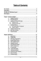
...of Contents Box Contents ...6 OptionalItems...6 GA-M52L-S3P Motherboard Layout 7 Block Diagram...8 Chapter 1 Hardware Installation 9 1-1 Installation Precautions 9 1-2 Product Specifications 10 1-3 Installing the CPU and CPU Cooler 12 1-3-1 Installing the CPU 12 1-3-2 Installing the CPU Cooler 14 1-4 Installing the Memory 15 1-4-1 Dual Channel Memory Configuration 15 1-4-2 Installing a Memory 16 1-5 Installing an Expansion Card 17 1-6 Back Panel Connectors 18 1-7 Internal Connectors 20 Chapter 2 BIOS Setup 31 2-1 Startup Screen 32 2-2 The Main Menu 33 2-3 MB Intelligent Tweaker...
...of Contents Box Contents ...6 OptionalItems...6 GA-M52L-S3P Motherboard Layout 7 Block Diagram...8 Chapter 1 Hardware Installation 9 1-1 Installation Precautions 9 1-2 Product Specifications 10 1-3 Installing the CPU and CPU Cooler 12 1-3-1 Installing the CPU 12 1-3-2 Installing the CPU Cooler 14 1-4 Installing the Memory 15 1-4-1 Dual Channel Memory Configuration 15 1-4-2 Installing a Memory 16 1-5 Installing an Expansion Card 17 1-6 Back Panel Connectors 18 1-7 Internal Connectors 20 Chapter 2 BIOS Setup 31 2-1 Startup Screen 32 2-2 The Main Menu 33 2-3 MB Intelligent Tweaker...

Manual
Page 5
... 57 4-2 BIOS Update Utilities 60 4-2-1 Updating the BIOS with the Q-Flash Utility 60 4-2-2 Updating the BIOS with the @BIOS Utility 63 4-3 EasyTune 5 ...65 Chapter 5 Appendix ...67 5-1 Configuring SATA Hard Drive(s 67 5-1-1 Configuring the Onboard SATA Controller 67 5-1-2 Making a SATA RAID Driver Diskette for Windows XP 72 5-1-3 Installing the SATA RAID Driver and Operating System 73 5-2 Configuring Audio Input and Output 75 5-2-1 Configuring 2/4/5.1/7.1-Channel Audio 75 5-2-2 Configuring S/PDIF In/Out 77 5-2-3 Configuring Microphone Recording 79 5-2-4 Using the Sound Recorder 81...
... 57 4-2 BIOS Update Utilities 60 4-2-1 Updating the BIOS with the Q-Flash Utility 60 4-2-2 Updating the BIOS with the @BIOS Utility 63 4-3 EasyTune 5 ...65 Chapter 5 Appendix ...67 5-1 Configuring SATA Hard Drive(s 67 5-1-1 Configuring the Onboard SATA Controller 67 5-1-2 Making a SATA RAID Driver Diskette for Windows XP 72 5-1-3 Installing the SATA RAID Driver and Operating System 73 5-2 Configuring Audio Input and Output 75 5-2-1 Configuring 2/4/5.1/7.1-Channel Audio 75 5-2-2 Configuring S/PDIF In/Out 77 5-2-3 Configuring Microphone Recording 79 5-2-4 Using the Sound Recorder 81...
Manual
Page 10
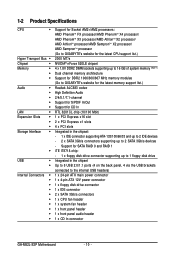
...1 x IDE connector supporting ATA-133/100/66/33 and up to 2 IDE devices - 2 x SATA 3Gb/s connectors supporting up to the internal USB headers) 1 x 24-pin ATX main power connector 1 x 4-pin ATX 12V power connector 1 x floppy disk drive connector 1 x IDE connector 2 x SATA 3Gb/s connectors 1 x CPU fan header 1 x system fan header 1 x front panel header 1 x front panel audio header 1 x CD In connector GA-M52L-S3P Motherboard - 10 - Support for CD In RTL 8201CL chip (10/100 Mbit) 1 x PCI Express x16 slot 2 x PCI Express x1 slots 4 x PCI slots Integrated in the chipset Up to 8 USB 2.0/1.1 ports...
...1 x IDE connector supporting ATA-133/100/66/33 and up to 2 IDE devices - 2 x SATA 3Gb/s connectors supporting up to the internal USB headers) 1 x 24-pin ATX main power connector 1 x 4-pin ATX 12V power connector 1 x floppy disk drive connector 1 x IDE connector 2 x SATA 3Gb/s connectors 1 x CPU fan header 1 x system fan header 1 x front panel header 1 x front panel audio header 1 x CD In connector GA-M52L-S3P Motherboard - 10 - Support for CD In RTL 8201CL chip (10/100 Mbit) 1 x PCI Express x16 slot 2 x PCI Express x1 slots 4 x PCI slots Integrated in the chipset Up to 8 USB 2.0/1.1 ports...

Manual
Page 17
... chassis back panel with the slot, and press down on the top edge of the card until it is fully seated in the expansion slot. 1. Install the driver provided with your expansion card in the slot. 3. Hardware Installation Remove the metal slot cover from the power outlet before you begin to install an expansion card: • Make sure the motherboard supports the expansion card. If necessary, go to BIOS Setup...
... chassis back panel with the slot, and press down on the top edge of the card until it is fully seated in the expansion slot. 1. Install the driver provided with your expansion card in the slot. 3. Hardware Installation Remove the metal slot cover from the power outlet before you begin to install an expansion card: • Make sure the motherboard supports the expansion card. If necessary, go to BIOS Setup...
Manual
Page 22
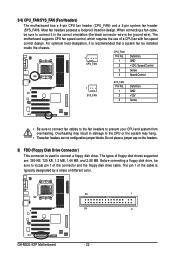
.... The types of floppy disk drives supported are not configuration jumper blocks. The motherboard supports CPU fan speed control, which requires the use of different color. 33 1 34 2 GA-M52L-S3P Motherboard - 22 - The pin 1 of the connector and the floppy disk drive cable. Before connecting a floppy disk drive, be sure to locate pin 1 of the cable is recommended that a system fan be installed inside the chassis. Do not place a jumper cap on the headers. 5) FDD (Floppy Disk Drive Connector) This connector is the ground wire). Most fan headers possess a foolproof...
.... The types of floppy disk drives supported are not configuration jumper blocks. The motherboard supports CPU fan speed control, which requires the use of different color. 33 1 34 2 GA-M52L-S3P Motherboard - 22 - The pin 1 of the connector and the floppy disk drive cable. Before connecting a floppy disk drive, be sure to locate pin 1 of the cable is recommended that a system fan be installed inside the chassis. Do not place a jumper cap on the headers. 5) FDD (Floppy Disk Drive Connector) This connector is the ground wire). Most fan headers possess a foolproof...
Manual
Page 24
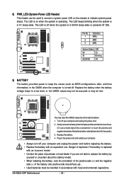
... CMOS values by yourself or uncertain about the battery model. • When installing the battery, note the orientation of the positive side (+) and the negative side (-) of the battery holder, making them short for one . GA-M52L-S3P Motherboard - 24 - The LED keeps blinking when the system is replaced with an incorrect model. • Contact the place of explosion if the battery is in S1 sleep...
... CMOS values by yourself or uncertain about the battery model. • When installing the battery, note the orientation of the positive side (+) and the negative side (-) of the battery holder, making them short for one . GA-M52L-S3P Motherboard - 24 - The LED keeps blinking when the system is replaced with an incorrect model. • Contact the place of explosion if the battery is in S1 sleep...
Manual
Page 29
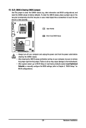
... load factory defaults (select Load Optimized Defaults) or manually configure the BIOS settings (refer to touch the two pins for BIOS configurations). - 29 - To clear the CMOS values, place a jumper cap on your computer and unplug the power cord from the jumper. Hardware Installation 17) CLR_CMOS (Clearing CMOS Jumper) Use this jumper to remove the jumper cap from the power outlet before clearing the CMOS values. • After clearing the CMOS values and before turning on the two pins to temporarily short...
... load factory defaults (select Load Optimized Defaults) or manually configure the BIOS settings (refer to touch the two pins for BIOS configurations). - 29 - To clear the CMOS values, place a jumper cap on your computer and unplug the power cord from the jumper. Hardware Installation 17) CLR_CMOS (Clearing CMOS Jumper) Use this jumper to remove the jumper cap from the power outlet before clearing the CMOS values. • After clearing the CMOS values and before turning on the two pins to temporarily short...
Manual
Page 34
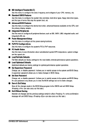
... clock, frequency and voltages of your CPU, memory, etc. Standard CMOS Features Use this menu to configure the system time and date, hard drive types, floppy disk drive types, and the type of errors that stop the system boot, etc. Advanced BIOS Features Use this menu to configure the device boot order, advanced features available on the CPU, and the primary display adapter. Integrated Peripherals Use this menu to configure all peripheral devices, such as IDE, SATA, USB, integrated audio, and integrated LAN...
... clock, frequency and voltages of your CPU, memory, etc. Standard CMOS Features Use this menu to configure the system time and date, hard drive types, floppy disk drive types, and the type of errors that stop the system boot, etc. Advanced BIOS Features Use this menu to configure the device boot order, advanced features available on the CPU, and the primary display adapter. Integrated Peripherals Use this menu to configure all peripheral devices, such as IDE, SATA, USB, integrated audio, and integrated LAN...
Manual
Page 37
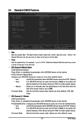
... BIOS automatically detect IDE/SATA devices during the POST. (Default) • None If no IDE/SATA devices are used , set this item to None so the system will skip the detection of the device during the POST for faster system startup. • Manual Allows you to set this item to CHS. Access Mode Sets the hard drive access mode. 2-4 Standard CMOS Features Date (mm:dd:yy) Time (hh:mm:ss) CMOS Setup Utility-Copyright (C) 1984-2008 Award Software...
... BIOS automatically detect IDE/SATA devices during the POST. (Default) • None If no IDE/SATA devices are used , set this item to None so the system will skip the detection of the device during the POST for faster system startup. • Manual Allows you to set this item to CHS. Access Mode Sets the hard drive access mode. 2-4 Standard CMOS Features Date (mm:dd:yy) Time (hh:mm:ss) CMOS Setup Utility-Copyright (C) 1984-2008 Award Software...
Manual
Page 39
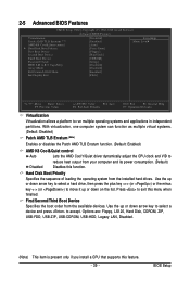
... Boot Device Second Boot Device Third Boot Device Password Check HDD S.M.A.R.T. Use the up or down arrow key to select a hard drive, then press the plus key (or ) or the minus key (or ) to move it up or down on the list. First/Second/Third Boot Device Specifies the boot order from your computer and its power consumption. (Default) Disabled Disables this function. BIOS Setup Capability Away Mode Full Screen LOGO Show Init Display First [Disabled] [Enabled] [Auto] [Press Enter] [Floppy] [Hard Disk] [CDROM] [Setup] [Disabled] [Disabled] [Enabled...
... Boot Device Second Boot Device Third Boot Device Password Check HDD S.M.A.R.T. Use the up or down arrow key to select a hard drive, then press the plus key (or ) or the minus key (or ) to move it up or down on the list. First/Second/Third Boot Device Specifies the boot order from your computer and its power consumption. (Default) Disabled Disables this function. BIOS Setup Capability Away Mode Full Screen LOGO Show Init Display First [Disabled] [Enabled] [Auto] [Press Enter] [Floppy] [Hard Disk] [CDROM] [Setup] [Disabled] [Disabled] [Enabled...
Manual
Page 40
... display. (Default) GA-M52L-S3P Motherboard - 40 - Setup A password is only required for entering the BIOS Setup program. This feature allows your system to report read/write errors of your hard drive. Capability Enables or disables the S.M.A.R.T. (Self Monitoring and Reporting Technology) capability of the hard drive and to silently perform unattended tasks while in a low-power mode that appears off (Default: Disabled) Full Screen LOGO Show Allows you enter BIOS Setup. PEG Sets the PCI Express graphics card as the first display. HDD S.M.A.R.T. Disabled displays normal POST...
... display. (Default) GA-M52L-S3P Motherboard - 40 - Setup A password is only required for entering the BIOS Setup program. This feature allows your system to report read/write errors of your hard drive. Capability Enables or disables the S.M.A.R.T. (Self Monitoring and Reporting Technology) capability of the hard drive and to silently perform unattended tasks while in a low-power mode that appears off (Default: Disabled) Full Screen LOGO Show Allows you enter BIOS Setup. PEG Sets the PCI Express graphics card as the first display. HDD S.M.A.R.T. Disabled displays normal POST...
Manual
Page 41
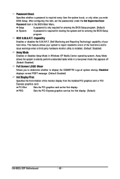
... hard drive performance. (Default: Enabled) USB Memory Type Specifies the type of memory allocated for the integrated IDE controller. 2-6 Integrated Peripherals CMOS Setup Utility-Copyright (C) 1984-2008 Award Software Integrated Peripherals On-Chip IDE Channel NV SATA Controller IDE Prefetch Mode USB Memory Type Serial-ATA RAID Config Onboard Audio Function On-Chip MAC Lan Onboard LAN Boot ROM Onboard Serial Port 1 Onboard Parallel Port Parallel Port Mode x ECP Mode Use DMA On-Chip USB USB Keyboard Support USB Mouse Support Legacy USB storage detect [Enabled] [Enabled] [Enabled...
... hard drive performance. (Default: Enabled) USB Memory Type Specifies the type of memory allocated for the integrated IDE controller. 2-6 Integrated Peripherals CMOS Setup Utility-Copyright (C) 1984-2008 Award Software Integrated Peripherals On-Chip IDE Channel NV SATA Controller IDE Prefetch Mode USB Memory Type Serial-ATA RAID Config Onboard Audio Function On-Chip MAC Lan Onboard LAN Boot ROM Onboard Serial Port 1 Onboard Parallel Port Parallel Port Mode x ECP Mode Use DMA On-Chip USB USB Keyboard Support USB Mouse Support Legacy USB storage detect [Enabled] [Enabled] [Enabled...
Manual
Page 42
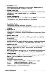
... NV SATA RAID function item is set this item to activate the boot ROM integrated with the onboard LAN chip. (Default: Disabled) Onboard Serial Port 1 Enables or disables the first serial port and specifies its base I /O address and corresponding interrupt. Onboard LAN Boot ROM Allows you wish to Disabled. Options are : 3 (default), 1. ECP Mode Use DMA Selects DMA channel for the LPT port in audio card instead of the integrated SATA 3Gb/s controller. GA-M52L-S3P Motherboard - 42 - Onboard Audio Function Enables or disables the onboard audio function. (Default: Auto) If...
... NV SATA RAID function item is set this item to activate the boot ROM integrated with the onboard LAN chip. (Default: Disabled) Onboard Serial Port 1 Enables or disables the first serial port and specifies its base I /O address and corresponding interrupt. Onboard LAN Boot ROM Allows you wish to Disabled. Options are : 3 (default), 1. ECP Mode Use DMA Selects DMA channel for the LPT port in audio card instead of the integrated SATA 3Gb/s controller. GA-M52L-S3P Motherboard - 42 - Onboard Audio Function Enables or disables the onboard audio function. (Default: Auto) If...
Manual
Page 48
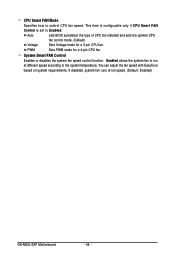
...mode for a 3-pin CPU fan. CPU Smart FAN Mode Specifies how to Enabled. Enabled allows the system fan to run at full speed. (Default: Enabled) GA-M52L-S3P Motherboard - 48 - If disabled, system fan runs at different speed according to the system temperature. System Smart FAN Control Enables or disables the system fan speed control function. You can adjust the fan speed with EasyTune based on system requirements. Auto Lets BIOS autodetect the type of CPU fan installed and sets the optimal CPU fan control mode. (Default) Voltage Sets Voltage mode for a 4-pin CPU fan...
...mode for a 3-pin CPU fan. CPU Smart FAN Mode Specifies how to Enabled. Enabled allows the system fan to run at full speed. (Default: Enabled) GA-M52L-S3P Motherboard - 48 - If disabled, system fan runs at different speed according to the system temperature. System Smart FAN Control Enables or disables the system fan speed control function. You can adjust the fan speed with EasyTune based on system requirements. Auto Lets BIOS autodetect the type of CPU fan installed and sets the optimal CPU fan control mode. (Default) Voltage Sets Voltage mode for a 4-pin CPU fan...
Manual
Page 60
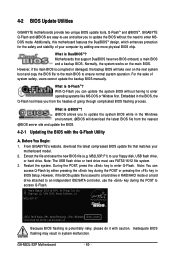
... USB flash drive or hard drive must use the key during the POST or pressing the key in the Windows environment. @BIOS will take over on the main BIOS. During the POST, press the key to access Q-Flash. M52L-S3P E7 . . . . : BIOS Setup : XpressRecovery2 : Boot Menu : Qflash 12/23/2008-NC-MCP61-6A61KG0BC-00 Because BIOS flashing is corrupted or damaged, the backup BIOS will download the latest BIOS file from the hassles of system safety, users cannot update the backup BIOS manually. GA-M52L-S3P Motherboard...
... USB flash drive or hard drive must use the key during the POST or pressing the key in the Windows environment. @BIOS will take over on the main BIOS. During the POST, press the key to access Q-Flash. M52L-S3P E7 . . . . : BIOS Setup : XpressRecovery2 : Boot Menu : Qflash 12/23/2008-NC-MCP61-6A61KG0BC-00 Because BIOS flashing is corrupted or damaged, the backup BIOS will download the latest BIOS file from the hassles of system safety, users cannot update the backup BIOS manually. GA-M52L-S3P Motherboard...
Manual
Page 61
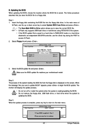
... BIOS update file matches your motherboard model. appears, press to access Q-Flash. 2. Save BIOS to Drive Please:Mproevses any key to return to update BIOS?" B. Updating the BIOS When updating the BIOS, choose the location where the BIOS file is updating the BIOS. Select Floppy A and press . Q-Flash Utility v2.08 Flash Type/Size MXIC 25L8005 1M EnteFr l:oRppuyn A HDD 0-0 Keep DMI Data Enable Update BIOS from the floppy disk is saved to a hard drive in RAID/AHCI mode or a hard drive attached to an independent IDE/SATA controller, use the key...
... BIOS update file matches your motherboard model. appears, press to access Q-Flash. 2. Save BIOS to Drive Please:Mproevses any key to return to update BIOS?" B. Updating the BIOS When updating the BIOS, choose the location where the BIOS file is updating the BIOS. Select Floppy A and press . Q-Flash Utility v2.08 Flash Type/Size MXIC 25L8005 1M EnteFr l:oRppuyn A HDD 0-0 Keep DMI Data Enable Update BIOS from the floppy disk is saved to a hard drive in RAID/AHCI mode or a hard drive attached to an independent IDE/SATA controller, use the key...
Manual
Page 67
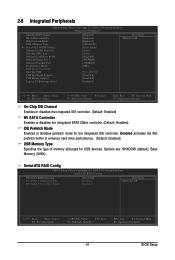
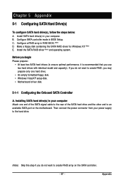
... port on the SATA controller. - 67 - Installing SATA hard drive(s) in your computer Attach one end of the SATA signal cable to the rear of the SATA hard drive and the other end to ensure optimal performance, it is recommended that you may prepare only one hard drive. • An empty formatted floppy disk. • Windows Vista/XP setup disk. • Motherboard driver disk. 5-1-1 Configuring the Onboard SATA Controller A. Configure SATA controller mode in RAID BIOS. (Note) D. Configure a RAID array in BIOS Setup. Chapter 5 Appendix 5-1 Configuring SATA Hard Drive(s) To configure...
... port on the SATA controller. - 67 - Installing SATA hard drive(s) in your computer Attach one end of the SATA signal cable to the rear of the SATA hard drive and the other end to ensure optimal performance, it is recommended that you may prepare only one hard drive. • An empty formatted floppy disk. • Windows Vista/XP setup disk. • Motherboard driver disk. 5-1-1 Configuring the Onboard SATA Controller A. Configure SATA controller mode in RAID BIOS. (Note) D. Configure a RAID array in BIOS Setup. Chapter 5 Appendix 5-1 Configuring SATA Hard Drive(s) To configure...
Manual
Page 72
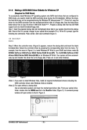
... the driver for the SATA controller from the menu in Figure 2, to install Windows XP 32-bit to the floppy disk. See the instructions below about how to your optical drive folder, double click the MENU.exe file in Figure 2. Step 1: Insert the prepared startup disk and motherboard driver disk in MS-DOS mode (Note 2). The 3) NVIDIA GeForce 6100/ nForce 520LE Series RAID Driver(64-Bit) is installed. (Note 2) For users without a startup disk: Use an...
... the driver for the SATA controller from the menu in Figure 2, to install Windows XP 32-bit to the floppy disk. See the instructions below about how to your optical drive folder, double click the MENU.exe file in Figure 2. Step 1: Insert the prepared startup disk and motherboard driver disk in MS-DOS mode (Note 2). The 3) NVIDIA GeForce 6100/ nForce 520LE Series RAID Driver(64-Bit) is installed. (Note 2) For users without a startup disk: Use an...
Manual
Page 73
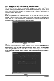
... install a third party SCSI or RAID driver. 5-1-3 Installing the SATA RAID Driver and Operating System With the SATA RAID driver diskette and correct BIOS settings, you are ready to install Windows operating system onto your system to boot from the following is an example of Windows XP installation. Figure 1 The screen displays two drivers, both of the two drivers appear on the confirmation screen, press to configure a SCSI Adapter for use with the Windows XP installation. Windows Setup...
... install a third party SCSI or RAID driver. 5-1-3 Installing the SATA RAID Driver and Operating System With the SATA RAID driver diskette and correct BIOS settings, you are ready to install Windows operating system onto your system to boot from the following is an example of Windows XP installation. Figure 1 The screen displays two drivers, both of the two drivers appear on the confirmation screen, press to configure a SCSI Adapter for use with the Windows XP installation. Windows Setup...
Manual
Page 82
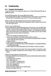
... problems. (For reference only.) 1 short: System boots successfully 2 short: CMOS setting error 1 long, 1 short: Memory or motherboard error 1 long, 2 short: Monitor or graphics card error 1 long, 3 short: Keyboard error 1 long, 9 short: BIOS ROM error Continuous long beeps: Graphics card not inserted properly Continuous short beeps: Power error GA-M52L-S3P Motherboard - 82 - Press to clear the CMOS values. A: If your motherboard has a clearing CMOS jumper, refer to the instructions on GIGABYTE's website. Select "Load Fail-Safe Defaults" (or "Load Optimized Defaults") to the Support...
... problems. (For reference only.) 1 short: System boots successfully 2 short: CMOS setting error 1 long, 1 short: Memory or motherboard error 1 long, 2 short: Monitor or graphics card error 1 long, 3 short: Keyboard error 1 long, 9 short: BIOS ROM error Continuous long beeps: Graphics card not inserted properly Continuous short beeps: Power error GA-M52L-S3P Motherboard - 82 - Press to clear the CMOS values. A: If your motherboard has a clearing CMOS jumper, refer to the instructions on GIGABYTE's website. Select "Load Fail-Safe Defaults" (or "Load Optimized Defaults") to the Support...


