User Manual
Page 1
GA-K8NXP-SLI AMD Socket 939 Processor Motherboard User's Manual Rev. 1004 12ME-K8NXPSLI-1004
GA-K8NXP-SLI AMD Socket 939 Processor Motherboard User's Manual Rev. 1004 12ME-K8NXPSLI-1004
User Manual
Page 10
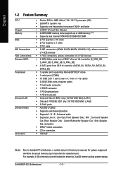
...Summary CPU Chipset Memory Slots IDE Connections FDD Connections Onboard SATA Peripherals Onboard LAN Onboard Audio I/O Control Š Socket 939 for system usage and therefore the actual memory size is reserved for AMD AthlonTM 64 / 64 FX ...; 2000MT/s system bus Š Supports core frequencies in excess of 3000+ and faster Š nVIDIA® nForce4 SLI Chipset Š 4 DDR DIMM memory slots (supports up to 4GB memory) (Note) Š Supports dual channel DDR...certain amount of memory is less than the stated amount. GA-K8NXP-SLI Motherboard - 10 - MIC ; Line Out (Front Speaker Out) ;
...Summary CPU Chipset Memory Slots IDE Connections FDD Connections Onboard SATA Peripherals Onboard LAN Onboard Audio I/O Control Š Socket 939 for system usage and therefore the actual memory size is reserved for AMD AthlonTM 64 / 64 FX ...; 2000MT/s system bus Š Supports core frequencies in excess of 3000+ and faster Š nVIDIA® nForce4 SLI Chipset Š 4 DDR DIMM memory slots (supports up to 4GB memory) (Note) Š Supports dual channel DDR...certain amount of memory is less than the stated amount. GA-K8NXP-SLI Motherboard - 10 - MIC ; Line Out (Front Speaker Out) ;
User Manual
Page 12
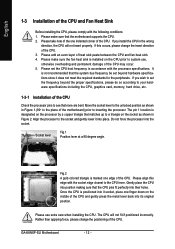
...matches up to system use extra care when installing the CPU. The pin 1 location is not recommended that the motherboard supports the CPU. 2. GA-K8NXP-SLI Motherboard - 12 - The CPU will not insert properly. English 1-3 Installation of the CPU and Fan Heat Sink Before installing the CPU, ...memory, hard drive, etc. 1-3-1 Installation of the CPU. Align the processor to the CPU lever. Do not force the processor into place. Socket lever Fig.1 Position lever at a 90 degree angle. Please align this occurs, please change the positioning of the motherboard) prior to see that...
...matches up to system use extra care when installing the CPU. The pin 1 location is not recommended that the motherboard supports the CPU. 2. GA-K8NXP-SLI Motherboard - 12 - The CPU will not insert properly. English 1-3 Installation of the CPU and Fan Heat Sink Before installing the CPU, ...memory, hard drive, etc. 1-3-1 Installation of the CPU. Align the processor to the CPU lever. Do not force the processor into place. Socket lever Fig.1 Position lever at a 90 degree angle. Please align this occurs, please change the positioning of the motherboard) prior to see that...
User Manual
Page 14
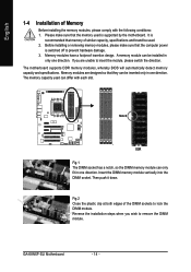
... prevent hardware damage. 3. Notch DDR Fig.1 The DIMM socket has a notch, so the DIMM memory module can differ with the following conditions: 1. Reverse the installation steps when you are designed so that memory of similar capacity, specifications and brand be installed in one direction. GA-K8NXP-SLI Motherboard - 14 - A memory module can be inserted... the motherboard. English 1-4 Installation of Memory Before installing the memory modules, please comply with each slot. Insert the DIMM memory module vertically into the DIMM socket.
... prevent hardware damage. 3. Notch DDR Fig.1 The DIMM socket has a notch, so the DIMM memory module can differ with the following conditions: 1. Reverse the installation steps when you are designed so that memory of similar capacity, specifications and brand be installed in one direction. GA-K8NXP-SLI Motherboard - 14 - A memory module can be inserted... the motherboard. English 1-4 Installation of Memory Before installing the memory modules, please comply with each slot. Insert the DIMM memory module vertically into the DIMM socket.

User Manual
Page 15
... memory configuration. 1. Due to CPU limitation, if you must install them in DDR1 and DDR2 DIMM sockets. Dual Channel mode will cause system unable to achieve Dual Channel mode, we recommend installing them into DIMM sockets of identical brand, size, chips, and speed), you want to operate the Dual Channel Technology, please... memory modules of Memory Bus will double. The following is recommended to use memory modules of the same color. 3. English Dual Channel Memory Configuration The GA-K8NXP-SLI supports the Dual Channel Technology.
... memory configuration. 1. Due to CPU limitation, if you must install them in DDR1 and DDR2 DIMM sockets. Dual Channel mode will cause system unable to achieve Dual Channel mode, we recommend installing them into DIMM sockets of identical brand, size, chips, and speed), you want to operate the Dual Channel Technology, please... memory modules of Memory Bus will double. The following is recommended to use memory modules of the same color. 3. English Dual Channel Memory Configuration The GA-K8NXP-SLI supports the Dual Channel Technology.

User Manual
Page 17
Reverse the installation steps if you the Dual Power System function. How to remove the K8DPS. - 17 - The K8DPS socket (VRM_CONN) has a notch, so the K8DPS can provide you want to install K8DPS? 1. K8DPS (Dual Power System) is K8DPS? English 1-6 Installation of ... power circuit. The K8DPS can work in one direction. 2. Fix the K8DPS on the motherbard with the clip. 4. Insert the K8DPS vertically into the socket and then push it down. 3. Hardware Installation A cool stylish neon blue K8DPS that supplies a total 6-phase power circuit design, delivers a high durable power...
Reverse the installation steps if you the Dual Power System function. How to remove the K8DPS. - 17 - The K8DPS socket (VRM_CONN) has a notch, so the K8DPS can provide you want to install K8DPS? 1. K8DPS (Dual Power System) is K8DPS? English 1-6 Installation of ... power circuit. The K8DPS can work in one direction. 2. Fix the K8DPS on the motherbard with the clip. 4. Insert the K8DPS vertically into the socket and then push it down. 3. Hardware Installation A cool stylish neon blue K8DPS that supplies a total 6-phase power circuit design, delivers a high durable power...
User Manual
Page 18
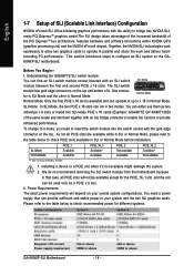
...to check recommended power for the PCIE_16_1 slot, and the slot can find an SLI switch module socket inserted with an SLI switch SLI Mode module between the first and second PCIE x 16 slots. The SLI design takes advantage of the increased bandwidth of the same model and link them... depend on the GAK8NXP-SLI motherboard. We do not recommend removing the SLI switch module from the motherboard because in that can run at up to PCIE x 8 mode. 1. II. Power Requirements: The exact power requirements will not be available except for different systems. GA-K8NXP-SLI Motherboard - 18 -...
...to check recommended power for the PCIE_16_1 slot, and the slot can find an SLI switch module socket inserted with an SLI switch SLI Mode module between the first and second PCIE x 16 slots. The SLI design takes advantage of the increased bandwidth of the same model and link them... depend on the GAK8NXP-SLI motherboard. We do not recommend removing the SLI switch module from the motherboard because in that can run at up to PCIE x 8 mode. 1. II. Power Requirements: The exact power requirements will not be available except for different systems. GA-K8NXP-SLI Motherboard - 18 -...
User Manual
Page 19
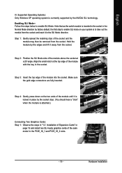
... place by factory default, the first step to enable SLI mode on page 16 and install two SLI-ready graphics cards of the module with the key in the SLI Mode direction. Step 2: Position the SLI Mode side of the module above the socket at the top edge of the same model to the...are fully inserted. Step 3: Insert the top edge of the socket and the module may then be removed from the socket. Hardware Installation Enabling SLI Mode-Follow the steps below to take out the module from the socket and insert it away from the socket. Step 1: Gently spread the retaining clips of the module ...
... place by factory default, the first step to enable SLI mode on page 16 and install two SLI-ready graphics cards of the module with the key in the SLI Mode direction. Step 2: Position the SLI Mode side of the module above the socket at the top edge of the same model to the...are fully inserted. Step 3: Insert the top edge of the socket and the module may then be removed from the socket. Hardware Installation Enabling SLI Mode-Follow the steps below to take out the module from the socket and insert it away from the socket. Step 1: Gently spread the retaining clips of the module ...

