User Manual
Page 4
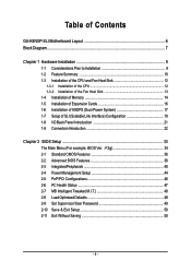
... of Contents GA-K8NXP-SLI Motherboard Layout 6 Block Diagram ...7 Chapter 1 Hardware Installation 9 1-1 Considerations Prior to Installation 9 1-2 Feature Summary 10 1-3 Installation of the CPU and Fan Heat Sink 12 1-3-1 Installation of the CPU 12 1-3-2 Installation of the Fan Heat Sink 13 1-4 Installation of Memory 14 1-5 Installation of Expansion Cards 16 1-6 Installation of K8DPS (Dual Power System 17 1-7 Setup of SLI (Scalable Link Interface) Configuration 18 1-8 I/O Back Panel Introduction 21 1-9 Connectors Introduction 22 Chapter 2 BIOS Setup 33 The Main Menu (For example...
... of Contents GA-K8NXP-SLI Motherboard Layout 6 Block Diagram ...7 Chapter 1 Hardware Installation 9 1-1 Considerations Prior to Installation 9 1-2 Feature Summary 10 1-3 Installation of the CPU and Fan Heat Sink 12 1-3-1 Installation of the CPU 12 1-3-2 Installation of the Fan Heat Sink 13 1-4 Installation of Memory 14 1-5 Installation of Expansion Cards 16 1-6 Installation of K8DPS (Dual Power System 17 1-7 Setup of SLI (Scalable Link Interface) Configuration 18 1-8 I/O Back Panel Introduction 21 1-9 Connectors Introduction 22 Chapter 2 BIOS Setup 33 The Main Menu (For example...
User Manual
Page 10
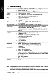
... Š Supports 2 / 4 / 6 / 8 channel audio Š Supports Line In ; Surround Speaker Out (Rear Speaker Out) ; Line Out (Front Speaker Out) ; Center/Subwoofer Speaker Out ; For example, 4 GB of memory size will instead be shown as 3.xxGB memory during system startup. GA-K8NXP-SLI Motherboard - 10 - English 1-2 Feature Summary CPU Chipset Memory Slots IDE Connections FDD Connections Onboard SATA Peripherals Onboard LAN Onboard Audio I/O Control Š Socket 939 for AMD AthlonTM 64 / 64 FX processor (K8) Š 2000MT/s system bus Š Supports core frequencies in excess...
... Š Supports 2 / 4 / 6 / 8 channel audio Š Supports Line In ; Surround Speaker Out (Rear Speaker Out) ; Line Out (Front Speaker Out) ; Center/Subwoofer Speaker Out ; For example, 4 GB of memory size will instead be shown as 3.xxGB memory during system startup. GA-K8NXP-SLI Motherboard - 10 - English 1-2 Feature Summary CPU Chipset Memory Slots IDE Connections FDD Connections Onboard SATA Peripherals Onboard LAN Onboard Audio I/O Control Š Socket 939 for AMD AthlonTM 64 / 64 FX processor (K8) Š 2000MT/s system bus Š Supports core frequencies in excess...
User Manual
Page 11
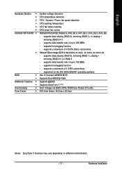
... Monitor Onboard SATA RAID Š Š BIOS Š Š Additional Features Š Š Overclocking Š Form Factor Š System voltage detection CPU temperature detection CPU / System / Power fan speed detection CPU warning temperature CPU fan failure warning CPU smart fan control Onboard nForce4 SLI chipset (S_ATA0_SB, S_ATA1_SB, S_ATA2_SB, S_ATA3_SB) - supports a maximum of 4 SATA connections - supports a maximum of 4 SATA 3Gb/s connections Onboard Silicon Image SiI3114 chip (SATA0_SII, SATA1_SII, SATA2_SII, SATA3_SII) - supported on different motherboards...
... Monitor Onboard SATA RAID Š Š BIOS Š Š Additional Features Š Š Overclocking Š Form Factor Š System voltage detection CPU temperature detection CPU / System / Power fan speed detection CPU warning temperature CPU fan failure warning CPU smart fan control Onboard nForce4 SLI chipset (S_ATA0_SB, S_ATA1_SB, S_ATA2_SB, S_ATA3_SB) - supports a maximum of 4 SATA connections - supports a maximum of 4 SATA 3Gb/s connections Onboard Silicon Image SiI3114 chip (SATA0_SII, SATA1_SII, SATA2_SII, SATA3_SII) - supported on different motherboards...
User Manual
Page 19
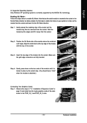
... is to enable SLI mode on page 16 and install two SLI-ready graphics cards of the module until it is attached.) Connecting Two Graphics Cards: Step 1: Observe the steps in "1-5 Installation of the module with the key in place by the NVIDIA SLI technology. Make sure the gold edge connectors are fully inserted. Supported Operating Systems: Only Windows XP operating system is currrently supported by the socket clips...
... is to enable SLI mode on page 16 and install two SLI-ready graphics cards of the module until it is attached.) Connecting Two Graphics Cards: Step 1: Observe the steps in "1-5 Installation of the module with the key in place by the NVIDIA SLI technology. Make sure the gold edge connectors are fully inserted. Supported Operating Systems: Only Windows XP operating system is currrently supported by the socket clips...
User Manual
Page 20
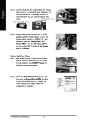
... slot, make sure to PEG(Slot2). Graphics Card Driver Setting: Step 1: After installing graphics card driver in operating system, right-click the NVIDIA icon in your system tray and then select NVIDIA Display. System will appear. Female slots on the bridge connector Gold edge connector on the PCIE_16_2 slot, set Init Display First to set Init Display First in the SLI multi-GPU dialog box. Then the SLI configuration is completed. GA-K8NXP-SLI Motherboard...
... slot, make sure to PEG(Slot2). Graphics Card Driver Setting: Step 1: After installing graphics card driver in operating system, right-click the NVIDIA icon in your system tray and then select NVIDIA Display. System will appear. Female slots on the bridge connector Gold edge connector on the PCIE_16_2 slot, set Init Display First to set Init Display First in the SLI multi-GPU dialog box. Then the SLI configuration is completed. GA-K8NXP-SLI Motherboard...
User Manual
Page 25
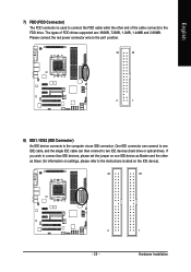
... IDE connector can then connect to the instructions located on settings, please refer to two IDE devices (hard drive or optical drive). If you wish to connect two IDE devices, please set the jumper on one IDE cable, and the single IDE cable can connect to one IDE device as Master and the other end of FDD drives supported are: 360KB, 720KB, 1.2MB, 1.44MB and 2.88MB. English 7) FDD (FDD Connector) The FDD connector is used to connect the FDD cable...
... IDE connector can then connect to the instructions located on settings, please refer to two IDE devices (hard drive or optical drive). If you wish to connect two IDE devices, please set the jumper on one IDE cable, and the single IDE cable can connect to one IDE device as Master and the other end of FDD drives supported are: 360KB, 720KB, 1.2MB, 1.44MB and 2.88MB. English 7) FDD (FDD Connector) The FDD connector is used to connect the FDD cable...
User Manual
Page 26
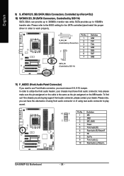
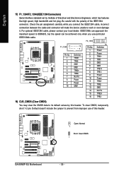
... SATA controller(s)and install the proper driver in order to work properly. 7 1 S_ATA_SB (Controlled by nForce4 SLI) 7 1 Pin No. 1 2 3 4 5 6 7 SATA_SII (Controlled by Sil3114) SATA 3Gb/s can have front audio connector. To find out if the chassis you must have the alternative of using front audio connector or of using rear audio connector to play sound. 10 9 2 1 Pin No. 1 2 3 4 5 6 7 8 9 10 Definition MIC GND MIC_BIAS Power Front Audio (R) Rear Audio (R)/ Return R NC No Pin Front Audio (L) Rear Audio (L)/ Return L GA-K8NXP-SLI Motherboard...
... SATA controller(s)and install the proper driver in order to work properly. 7 1 S_ATA_SB (Controlled by nForce4 SLI) 7 1 Pin No. 1 2 3 4 5 6 7 SATA_SII (Controlled by Sil3114) SATA 3Gb/s can have front audio connector. To find out if the chassis you must have the alternative of using front audio connector or of using rear audio connector to play sound. 10 9 2 1 Pin No. 1 2 3 4 5 6 7 8 9 10 Definition MIC GND MIC_BIAS Power Front Audio (R) Rear Audio (R)/ Return R NC No Pin Front Audio (L) Rear Audio (L)/ Return L GA-K8NXP-SLI Motherboard...
User Manual
Page 30
... GND TPB0+ TPB0No Pin Power Power GND 1 Pin No. 1 2 3 4 5 6 7 8 9 10 11 12 13 14 15 16 15 Definition Power Power TPA1+ TPA1GND GND TPB1+ TPB1Power Power TPA2+ TPA2GND No Pin TPB2+ TPB2- 18) CLR_CMOS (Clear CMOS) You may clear the CMOS data to work or even damage it. English 17) F1_1394/F2_1394 (IEEE 1394 Connectors) Serial interface standard set by this header. Open: Normal 1 Short: Clear CMOS 1 GA-K8NXP-SLI Motherboard - 30 - Be careful...
... GND TPB0+ TPB0No Pin Power Power GND 1 Pin No. 1 2 3 4 5 6 7 8 9 10 11 12 13 14 15 16 15 Definition Power Power TPA1+ TPA1GND GND TPB1+ TPB1Power Power TPA2+ TPA2GND No Pin TPB2+ TPB2- 18) CLR_CMOS (Clear CMOS) You may clear the CMOS data to work or even damage it. English 17) F1_1394/F2_1394 (IEEE 1394 Connectors) Serial interface standard set by this header. Open: Normal 1 Short: Clear CMOS 1 GA-K8NXP-SLI Motherboard - 30 - Be careful...
User Manual
Page 34
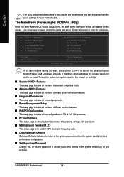
... temperature, voltage, fan speed, etc. „ MB Intelligent Tweaker(M.I .T.) Load Optimized Defaults Set Supervisor Password Set User Password Save & Exit Setup Exit Without Saving Esc: Quit F8: Dual BIOS/Q-Flash KLJI: Select Item F10: Save & Exit Setup Time, Date, Hard Disk Type... It allows you to limit access to the system and Setup, or just to accept or enter the sub-menu. If you can't find the setting you enter Award BIOS CMOS Setup Utility, the Main Menu (as usual. GA-K8NXP-SLI Motherboard - 34 - The Main Menu...
... temperature, voltage, fan speed, etc. „ MB Intelligent Tweaker(M.I .T.) Load Optimized Defaults Set Supervisor Password Set User Password Save & Exit Setup Exit Without Saving Esc: Quit F8: Dual BIOS/Q-Flash KLJI: Select Item F10: Save & Exit Setup Time, Date, Hard Disk Type... It allows you to limit access to the system and Setup, or just to accept or enter the sub-menu. If you can't find the setting you enter Award BIOS CMOS Setup Utility, the Main Menu (as usual. GA-K8NXP-SLI Motherboard - 34 - The Main Menu...
User Manual
Page 36
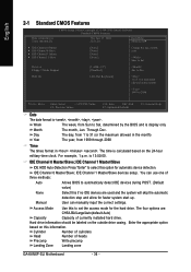
.... IDE Channel 1 Master/Slave devices setup. Access Mode Use this option for faster system start up. Cylinder Number of cylinders Head Number of currently installed hard drive. Drive A Floppy 3 Mode Support [1.44M, 3.5"] [Disabled] Jan. Halt On [All, But Keyboard] 1 to 31 (or maximum allowed in . For example, 1 p.m. IDE Channel 0 Master/Slave; You can manually input the correct settings. User can use one of three methods: Auto Allows BIOS to select this to 2098 KLJI: Move Enter: Select...
.... IDE Channel 1 Master/Slave devices setup. Access Mode Use this option for faster system start up. Cylinder Number of cylinders Head Number of currently installed hard drive. Drive A Floppy 3 Mode Support [1.44M, 3.5"] [Disabled] Jan. Halt On [All, But Keyboard] 1 to 31 (or maximum allowed in . For example, 1 p.m. IDE Channel 0 Master/Slave; You can manually input the correct settings. User can use one of three methods: Auto Allows BIOS to select this to 2098 KLJI: Move Enter: Select...
User Manual
Page 40
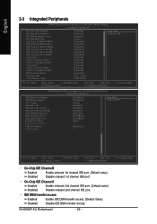
... onboard 2nd channel IDE port. (Default value) Disabled Disable onboard 2nd channel IDE port. English 2-3 Integrated Peripherals CMOS Setup Utility-Copyright (C) 1984-2005 Award Software Integrated Peripherals On-Chip IDE Channel0 On-Chip IDE Channel1 IDE DMA transfer access On-Chip MAC Lan On-Chip LAN BOOT ROM IDE/SATA RAID function IDE Primary Master RAID IDE Primary Slave RAID IDE Secndry Master RAID IDE Secndry Slave RAID Serial-ATA 1 SATA 1 Primary RAID SATA 1 Secondary RAID Serial-ATA 2 SATA 2 Primary RAID SATA 2 Secondary RAID IDE Prefetch Mode On-Chip USB USB Memory Type [Enabled...
... onboard 2nd channel IDE port. (Default value) Disabled Disable onboard 2nd channel IDE port. English 2-3 Integrated Peripherals CMOS Setup Utility-Copyright (C) 1984-2005 Award Software Integrated Peripherals On-Chip IDE Channel0 On-Chip IDE Channel1 IDE DMA transfer access On-Chip MAC Lan On-Chip LAN BOOT ROM IDE/SATA RAID function IDE Primary Master RAID IDE Primary Slave RAID IDE Secndry Master RAID IDE Secndry Slave RAID Serial-ATA 1 SATA 1 Primary RAID SATA 1 Secondary RAID Serial-ATA 2 SATA 2 Primary RAID SATA 2 Secondary RAID IDE Prefetch Mode On-Chip USB USB Memory Type [Enabled...

User Manual
Page 42
... USB Memory Type to invoke the boot ROM of the Sil3114 controller. Disable USB mouse support. (Default value) AC97 Audio Auto Enable onboard AC'97 audio function. (Default value) Disabled Disable this function. Onboard LAN control (LAN1) Enabled Enable onboard LAN chip function.(Default value) Disabled Disable onboard LAN chip function. If you wish to set either RAID or non-RAID mode, you have to enter the Sil3114 RAID BIOS utility. (Upon system reboot, press or key to enable or disable the Serial ATA function of the onboard LAN chip. Disabled Disable USB keyboard...
... USB Memory Type to invoke the boot ROM of the Sil3114 controller. Disable USB mouse support. (Default value) AC97 Audio Auto Enable onboard AC'97 audio function. (Default value) Disabled Disable this function. Onboard LAN control (LAN1) Enabled Enable onboard LAN chip function.(Default value) Disabled Disable onboard LAN chip function. If you wish to set either RAID or non-RAID mode, you have to enter the Sil3114 RAID BIOS utility. (Upon system reboot, press or key to enable or disable the Serial ATA function of the onboard LAN chip. Disabled Disable USB keyboard...
User Manual
Page 50
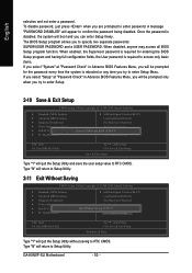
...PASSWORD and a USER PASSWORD. GA-K8NXP-SLI Motherboard - 50 - English selection and not enter a password. Once the password is rebooted or any time you to enter password. The BIOS Setup program allows you try to enter Setup Menu. To disable password, just press when you try to enter Setup. 2-10 Save & Exit Setup CMOS Setup Utility-Copyright (C) 1984-2005 Award Software ` Standard CMOS Features ` Advanced BIOS Features ` Integrated Peripherals ` Power Management Setup ` PnP/PCI Configurations ` PC Health Status ` MB Intelligent Tweaker(M.I .T.) Load Optimized Defaults Set...
...PASSWORD and a USER PASSWORD. GA-K8NXP-SLI Motherboard - 50 - English selection and not enter a password. Once the password is rebooted or any time you to enter password. The BIOS Setup program allows you try to enter Setup Menu. To disable password, just press when you try to enter Setup. 2-10 Save & Exit Setup CMOS Setup Utility-Copyright (C) 1984-2005 Award Software ` Standard CMOS Features ` Advanced BIOS Features ` Integrated Peripherals ` Power Management Setup ` PnP/PCI Configurations ` PC Health Status ` MB Intelligent Tweaker(M.I .T.) Load Optimized Defaults Set...
User Manual
Page 56
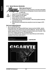
... size. 6. Once the computer has restarted, the phrase "Boot from CD:" appears, press any key to the IDE1 Master 3. Execute Restore Utility 3. Set Password 5. Verifying DMI Pool Data Boot from CD: Boot from CD-ROM. Execute Backup Utility 2. Boot from CD-ROM (BMP Mode) Enter the BIOS menu, select "Advanced BIOS Feature" and set as the boot partition. Xpress Recovery is Xpress Recovery ? Exit and Restart Build 2011 GA-K8NXP-SLI Motherboard - 56 - Must be connected...
... size. 6. Once the computer has restarted, the phrase "Boot from CD:" appears, press any key to the IDE1 Master 3. Execute Restore Utility 3. Set Password 5. Verifying DMI Pool Data Boot from CD: Boot from CD-ROM. Execute Backup Utility 2. Boot from CD-ROM (BMP Mode) Enter the BIOS menu, select "Advanced BIOS Feature" and set as the boot partition. Xpress Recovery is Xpress Recovery ? Exit and Restart Build 2011 GA-K8NXP-SLI Motherboard - 56 - Must be connected...

User Manual
Page 59
... is Dual BIOS Technology? b. English 4-1-3 Flash BIOS Method Introduction A. Appendix CMOS Setup Utility-Copyright (C) 1984-2004 Award Software Standard CMOS Features Advanced BIOS Features Integrated Peripherals Power Management Setup PnP/PCI Configurations PC Health Status MB Intelligent Tweaker(M.I.T.) Load Fail-Safe Defaults Load Optimized Defaults Set Supervisor Password Set User Password Save & Exit Setup Exit Without Saving ESC: Quit F8: Dual BIOS/Q-Flash : Select Item F10: Save & Exit Setup Time, Date, Hard Disk Type... How to Floppy PgDn/PgUp: Modify : Move ESC: Reset...
... is Dual BIOS Technology? b. English 4-1-3 Flash BIOS Method Introduction A. Appendix CMOS Setup Utility-Copyright (C) 1984-2004 Award Software Standard CMOS Features Advanced BIOS Features Integrated Peripherals Power Management Setup PnP/PCI Configurations PC Health Status MB Intelligent Tweaker(M.I.T.) Load Fail-Safe Defaults Load Optimized Defaults Set Supervisor Password Set User Password Save & Exit Setup Exit Without Saving ESC: Quit F8: Dual BIOS/Q-Flash : Select Item F10: Save & Exit Setup Time, Date, Hard Disk Type... How to Floppy PgDn/PgUp: Modify : Move ESC: Reset...
User Manual
Page 62
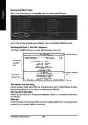
...: Dual BIOS/Q-Flash Select Language Load Fail-Safe Defaults Load Optimized Defaults Set Supervisor Password Set User Password Save & Exit Setup Exit Without Saving F3: Change Language F10: Save & Exit Setup Time, Date, Hard Disk Type... GA-K8NXP-SLI Motherboard - 62 - Action bar: Contains the names of the following key components. Task menu for Dual BIOS utility Task menu for Q-Flash utility: Contains the names of eight tasks and two item showing information about the BIOS ROM type. Step 2: Press F8 button on your keyboard and...
...: Dual BIOS/Q-Flash Select Language Load Fail-Safe Defaults Load Optimized Defaults Set Supervisor Password Set User Password Save & Exit Setup Exit Without Saving F3: Change Language F10: Save & Exit Setup Time, Date, Hard Disk Type... GA-K8NXP-SLI Motherboard - 62 - Action bar: Contains the names of the following key components. Task menu for Dual BIOS utility Task menu for Q-Flash utility: Contains the names of eight tasks and two item showing information about the BIOS ROM type. Step 2: Press F8 button on your keyboard and...
User Manual
Page 68
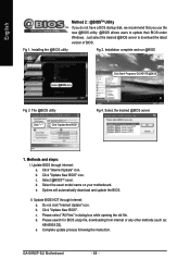
Click Start/ Programs/ GIGABYTE/@BIOS Fig 3. The @BIOS utility Click " " Click "Update New BIOS" Fig 4. Update BIOS through Internet: a. b. Update BIOS NOT through Internet: a. d. System will automatically download and update the BIOS. II. b. Complete update process following the instruction. Installing the @BIOS utility Fig 2. c. d. Click "Update New BIOS". Just select the desired @BIOS server to update their BIOS under Windows. Select the exact model name on your motherboard. Do not click "Internet Update" icon. GA-K8NXP-SLI Motherboard - 68 - Select...
Click Start/ Programs/ GIGABYTE/@BIOS Fig 3. The @BIOS utility Click " " Click "Update New BIOS" Fig 4. Update BIOS through Internet: a. b. Update BIOS NOT through Internet: a. d. System will automatically download and update the BIOS. II. b. Complete update process following the instruction. Installing the @BIOS utility Fig 2. c. d. Click "Update New BIOS". Just select the desired @BIOS server to update their BIOS under Windows. Select the exact model name on your motherboard. Do not click "Internet Update" icon. GA-K8NXP-SLI Motherboard - 68 - Select...
User Manual
Page 71
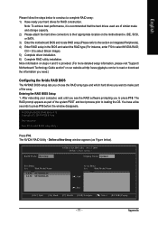
... setup information, please visit "Support\ Motherboard\ Technology Guide section" on steps 4 and 5 is recommended that the hard drives used are of similar make part of the system POST and boot process prior to select NVIDIA RAID; Press F10 to press F10 before the window disappears. NVIDIA RAID IDE ROM BIOS 4.76 Copyright (C) 2004 NVIDIA Corp. Ctrl + S to the section on the motherboard ie. The NVIDIA RAID Utility - After rebooting your hard drives...
... setup information, please visit "Support\ Motherboard\ Technology Guide section" on steps 4 and 5 is recommended that the hard drives used are of similar make part of the system POST and boot process prior to select NVIDIA RAID; Press F10 to press F10 before the window disappears. NVIDIA RAID IDE ROM BIOS 4.76 Copyright (C) 2004 NVIDIA Corp. Ctrl + S to the section on the motherboard ie. The NVIDIA RAID Utility - After rebooting your hard drives...
User Manual
Page 75
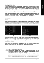
..., change to the floppy disk. Your system will have to install the RAID drivers. Press 0 to SATA hard disks on -screen instructions to complete the installation. (Each time you add a new hard drive to a RAID array, the RAID driver will then automatically zip and transfer this floppy disk. Use an alternative system and insert the GIGABYTE motherboard driver CD-ROM. From the CD-ROM drive (example: D:\) double click the MENU.exe file in your system. A command prompt window will...
..., change to the floppy disk. Your system will have to install the RAID drivers. Press 0 to SATA hard disks on -screen instructions to complete the installation. (Each time you add a new hard drive to a RAID array, the RAID driver will then automatically zip and transfer this floppy disk. Use an alternative system and insert the GIGABYTE motherboard driver CD-ROM. From the CD-ROM drive (example: D:\) double click the MENU.exe file in your system. A command prompt window will...
User Manual
Page 82
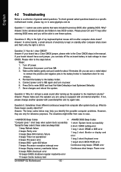
... GA-K8NXP-SLI Motherboard - 82 - Turn off the on-board battery to leak voltage to case. Answer: Please make sure the speaker you identify the possible computer problems. However, they are always fatal. 1 beep Refresh failure 2 beeps Parity error 3 beeps Base 64K memory failure 4 beeps Timer not operational 5 beeps Processor error 6 beeps 8042 - Answer: The beep codes below : Steps: 1. To check general asked questions. AWARD BIOS Beep Codes 1 short: System boots successfully 2 short: CMOS setting error 1 long 1 short: DRAM or M/B error 1 long 2 short: Monitor or display card...
... GA-K8NXP-SLI Motherboard - 82 - Turn off the on-board battery to leak voltage to case. Answer: Please make sure the speaker you identify the possible computer problems. However, they are always fatal. 1 beep Refresh failure 2 beeps Parity error 3 beeps Base 64K memory failure 4 beeps Timer not operational 5 beeps Processor error 6 beeps 8042 - Answer: The beep codes below : Steps: 1. To check general asked questions. AWARD BIOS Beep Codes 1 short: System boots successfully 2 short: CMOS setting error 1 long 1 short: DRAM or M/B error 1 long 2 short: Monitor or display card...


