User Manual
Page 1
GA-K8NXP-SLI AMD Socket 939 Processor Motherboard User's Manual Rev. 1004 12ME-K8NXPSLI-1004
GA-K8NXP-SLI AMD Socket 939 Processor Motherboard User's Manual Rev. 1004 12ME-K8NXPSLI-1004

User Manual
Page 2
Motherboard GA-K8NXP-SLI Dec. 14, 2004 Motherboard GA-K8NXP-SLI Dec. 14, 2004
Motherboard GA-K8NXP-SLI Dec. 14, 2004 Motherboard GA-K8NXP-SLI Dec. 14, 2004
User Manual
Page 4
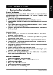
Table of Contents GA-K8NXP-SLI Motherboard Layout 6 Block Diagram ...7 Chapter 1 Hardware Installation 9 1-1 Considerations Prior to Installation 9 1-2 Feature Summary 10 1-3 Installation of the CPU and Fan Heat Sink 12 1-3-1 Installation...1-3-2 Installation of the Fan Heat Sink 13 1-4 Installation of Memory 14 1-5 Installation of Expansion Cards 16 1-6 Installation of K8DPS (Dual Power System 17 1-7 Setup of SLI (Scalable Link Interface) Configuration 18 1-8 I/O Back Panel Introduction 21 1-9 Connectors Introduction 22 Chapter 2 BIOS Setup 33 The Main Menu (For example: BIOS Ver. :...
Table of Contents GA-K8NXP-SLI Motherboard Layout 6 Block Diagram ...7 Chapter 1 Hardware Installation 9 1-1 Considerations Prior to Installation 9 1-2 Feature Summary 10 1-3 Installation of the CPU and Fan Heat Sink 12 1-3-1 Installation...1-3-2 Installation of the Fan Heat Sink 13 1-4 Installation of Memory 14 1-5 Installation of Expansion Cards 16 1-6 Installation of K8DPS (Dual Power System 17 1-7 Setup of SLI (Scalable Link Interface) Configuration 18 1-8 I/O Back Panel Introduction 21 1-9 Connectors Introduction 22 Chapter 2 BIOS Setup 33 The Main Menu (For example: BIOS Ver. :...
User Manual
Page 9
These stickers are connected. 4. Damage due to be an unofficial Gigabyte product. - 9 - Product determined to natural disaster, accident or human cause. 2. Prior to installing the electronic components, please have a problem related.... 3. Damage due to use exceeding the permitted parameters. 6. English Chapter 1 Hardware Installation 1-1 Considerations Prior to Installation Preparing Your Computer The motherboard contains numerous delicate electronic circuits and components which can lead to damage to system components as well as physical harm to the user. 8. Before...
These stickers are connected. 4. Damage due to be an unofficial Gigabyte product. - 9 - Product determined to natural disaster, accident or human cause. 2. Prior to installing the electronic components, please have a problem related.... 3. Damage due to use exceeding the permitted parameters. 6. English Chapter 1 Hardware Installation 1-1 Considerations Prior to Installation Preparing Your Computer The motherboard contains numerous delicate electronic circuits and components which can lead to damage to system components as well as physical harm to the user. 8. Before...
User Manual
Page 10
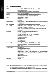
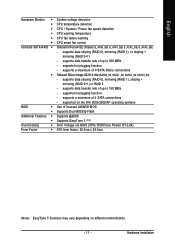
...138; Supports 2 / 4 / 6 / 8 channel audio Š Supports Line In ; Center/Subwoofer Speaker Out ; Line Out (Front Speaker Out) ; GA-K8NXP-SLI Motherboard - 10 - English 1-2 Feature Summary CPU Chipset Memory Slots IDE Connections FDD Connections Onboard SATA Peripherals Onboard LAN Onboard Audio I/O Control Š Socket 939 for...K8) Š 2000MT/s system bus Š Supports core frequencies in excess of 3000+ and faster Š nVIDIA® nForce4 SLI Chipset Š 4 DDR DIMM memory slots (supports up to standard PC architecture, a certain amount of memory is reserved for system ...
...138; Supports 2 / 4 / 6 / 8 channel audio Š Supports Line In ; Center/Subwoofer Speaker Out ; Line Out (Front Speaker Out) ; GA-K8NXP-SLI Motherboard - 10 - English 1-2 Feature Summary CPU Chipset Memory Slots IDE Connections FDD Connections Onboard SATA Peripherals Onboard LAN Onboard Audio I/O Control Š Socket 939 for...K8) Š 2000MT/s system bus Š Supports core frequencies in excess of 3000+ and faster Š nVIDIA® nForce4 SLI Chipset Š 4 DDR DIMM memory slots (supports up to standard PC architecture, a certain amount of memory is reserved for system ...
User Manual
Page 11
... temperature detection CPU / System / Power fan speed detection CPU warning temperature CPU fan failure warning CPU smart fan control Onboard nForce4 SLI chipset (S_ATA0_SB, S_ATA1_SB, S_ATA2_SB, S_ATA3_SB) - supported on different motherboards. - 11 - supports a maximum of licensed AWARD BIOS Supports Dual BIOS/Q-Flash Supports @BIOS Supports EasyTune 5 (Note) Over Voltage via BIOS (CPU...
... temperature detection CPU / System / Power fan speed detection CPU warning temperature CPU fan failure warning CPU smart fan control Onboard nForce4 SLI chipset (S_ATA0_SB, S_ATA1_SB, S_ATA2_SB, S_ATA3_SB) - supported on different motherboards. - 11 - supports a maximum of licensed AWARD BIOS Supports Dual BIOS/Q-Flash Supports @BIOS Supports EasyTune 5 (Note) Over Voltage via BIOS (CPU...
User Manual
Page 12
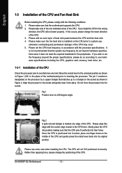
...the processor. The pin 1 location is designated on the socket as shown in Figure 1.(90o to the plane of the motherboard) prior to set the CPU host frequency in Figure 2. Do not force the processor into place. Socket lever Fig.1... with the processor specifications. Please take note of the one edge of the CPU. Please make sure that the motherboard supports the CPU. 2. Please set the frequency beyond hardware specifications since it does not meet the required standards for...heat sink. 4. Once the CPU is marked one indented corner of the CPU. GA-K8NXP-SLI Motherboard - 12 -
...the processor. The pin 1 location is designated on the socket as shown in Figure 1.(90o to the plane of the motherboard) prior to set the CPU host frequency in Figure 2. Do not force the processor into place. Socket lever Fig.1... with the processor specifications. Please take note of the one edge of the CPU. Please make sure that the motherboard supports the CPU. 2. Please set the frequency beyond hardware specifications since it does not meet the required standards for...heat sink. 4. Once the CPU is marked one indented corner of the CPU. GA-K8NXP-SLI Motherboard - 12 -

User Manual
Page 13
... of the Fan Heat Sink Fig.1 Before installing the CPU fan heat sink, please first add an even layer of heat sink paste on the motherboard so that either thermal tape rather than heat sink paste be used for detailed installation instructions). Fig.2 Please connect the fan heat sink power connector...
... of the Fan Heat Sink Fig.1 Before installing the CPU fan heat sink, please first add an even layer of heat sink paste on the motherboard so that either thermal tape rather than heat sink paste be used for detailed installation instructions). Fig.2 Please connect the fan heat sink power connector...
User Manual
Page 14
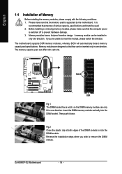
...DIMM memory module vertically into the DIMM socket. Then push it down. If you wish to insert the module, please switch the direction. GA-K8NXP-SLI Motherboard - 14 - English 1-4 Installation of Memory Before installing the memory modules, please comply with each slot. Memory modules are unable to ...specifications and brand be used can only fit in only one direction. It is recommended that the computer power is supported by the motherboard. Notch DDR Fig.1 The DIMM socket has a notch, so the DIMM memory module can differ with the following conditions: 1. Reverse...
...DIMM memory module vertically into the DIMM socket. Then push it down. If you wish to insert the module, please switch the direction. GA-K8NXP-SLI Motherboard - 14 - English 1-4 Installation of Memory Before installing the memory modules, please comply with each slot. Memory modules are unable to ...specifications and brand be used can only fit in only one direction. It is recommended that the computer power is supported by the motherboard. Notch DDR Fig.1 The DIMM socket has a notch, so the DIMM memory module can differ with the following conditions: 1. Reverse...
User Manual
Page 16
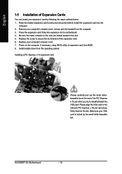
... your VGA card is locked by following the steps outlined below: 1. Remove your computer's chassis cover. 7. Install related driver from BIOS. 8. GA-K8NXP-SLI Motherboard - 16 - Be sure the metal contacts on the computer, if necessary, setup BIOS utility of expansion card from the operating system. Installing a...of the expansion card. 6. Replace the screw to install/uninstall the VGA card. Power on the card are indeed seated in motherboard. 4. English 1-5 Installation of Expansion Cards You can install your expansion card by the small white-drawable bar. Please align ...
... your VGA card is locked by following the steps outlined below: 1. Remove your computer's chassis cover. 7. Install related driver from BIOS. 8. GA-K8NXP-SLI Motherboard - 16 - Be sure the metal contacts on the computer, if necessary, setup BIOS utility of expansion card from the operating system. Installing a...of the expansion card. 6. Replace the screw to install/uninstall the VGA card. Power on the card are indeed seated in motherboard. 4. English 1-5 Installation of Expansion Cards You can install your expansion card by the small white-drawable bar. Please align ...

User Manual
Page 17
... on the motherbard with the clip. 4. K8DPS (Dual Power System) is a daughter card which can only fit in a Dual Power System: Parallel Mode-K8DPS and motherboard CPU power can work in one direction. 2. The K8DPS can work simultaneously, providing a total of K8DPS (Dual Power System) What is K8DPS? A cool stylish neon...
... on the motherbard with the clip. 4. K8DPS (Dual Power System) is a daughter card which can only fit in a Dual Power System: Parallel Mode-K8DPS and motherboard CPU power can work in one direction. 2. The K8DPS can work simultaneously, providing a total of K8DPS (Dual Power System) What is K8DPS? A cool stylish neon...
User Manual
Page 18
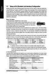
... be available except for different systems. GA-K8NXP-SLI Motherboard - 18 - Understanding the GIGABYTE SLI switch module: You can find an SLI switch module socket inserted with an SLI switch SLI Mode module between the first and second PCIE x 16 slots. SLI Mode Normal Mode PCIE_1 Available Available PCIE_16_1...As not all PCIE slots will depend on the GAK8NXP-SLI motherboard. Together, the NVIDIA SLI technologies work seamlessly to allow two graphics cards to configure an SLI system on your system and the two SLI graphics cards. This section introduces steps to operate in ...
... be available except for different systems. GA-K8NXP-SLI Motherboard - 18 - Understanding the GIGABYTE SLI switch module: You can find an SLI switch module socket inserted with an SLI switch SLI Mode module between the first and second PCIE x 16 slots. SLI Mode Normal Mode PCIE_1 Available Available PCIE_16_1...As not all PCIE slots will depend on the GAK8NXP-SLI motherboard. Together, the NVIDIA SLI technologies work seamlessly to allow two graphics cards to configure an SLI system on your system and the two SLI graphics cards. This section introduces steps to operate in ...
User Manual
Page 20
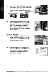
... the bridge connector Gold edge connector on the PCIE_16_1 slot, make sure to set Init Display First to PEG(Slot2). curely fit onto the SLI gold edge connetors of the two graphics cards for display output. if you click Apply. English Step 2: Insert the... Make sure the two mini female slots on top of both cards. Step 2: Select SLI multi-GPU from the side menu and then select the Enable SLI multi-GPU checkbox in your system tray and then select NVIDIA Display. GA-K8NXP-SLI Motherboard - 20 - Graphics Card Driver Setting: Step 1: After installing graphics card driver in ...
... the bridge connector Gold edge connector on the PCIE_16_1 slot, make sure to set Init Display First to PEG(Slot2). curely fit onto the SLI gold edge connetors of the two graphics cards for display output. if you click Apply. English Step 2: Insert the... Make sure the two mini female slots on top of both cards. Step 2: Select SLI multi-GPU from the side menu and then select the Enable SLI multi-GPU checkbox in your system tray and then select NVIDIA Display. GA-K8NXP-SLI Motherboard - 20 - Graphics Card Driver Setting: Step 1: After installing graphics card driver in ...

User Manual
Page 22
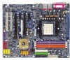
... configure 2-/4-/6-/8-channel audio functioning. 1-9 Connectors Introduction 13 8 11 13 1) ATX_12V 2) ATX (Power Connector) 3) CPU_FAN 4) SYS_FAN 5) PWR_FAN 6) NB_FAN 7) FDD 8) IDE1 / IDE2 9) S_ATA0/1/2/3_SB 10) SATA0/1/2/3_SII GA-K8NXP-SLI Motherboard 2 5 7 19 6 18 9 12 14 4 15 17 10 16 11) F_AUDIO 12) F_PANEL 13) CD_IN 14) PWR_LED 15) IR/CIR 16) F_USB1 / F_USB2/F_USB3 17) F1_1394...
... configure 2-/4-/6-/8-channel audio functioning. 1-9 Connectors Introduction 13 8 11 13 1) ATX_12V 2) ATX (Power Connector) 3) CPU_FAN 4) SYS_FAN 5) PWR_FAN 6) NB_FAN 7) FDD 8) IDE1 / IDE2 9) S_ATA0/1/2/3_SB 10) SATA0/1/2/3_SII GA-K8NXP-SLI Motherboard 2 5 7 19 6 18 9 12 14 4 15 17 10 16 11) F_AUDIO 12) F_PANEL 13) CD_IN 14) PWR_LED 15) IR/CIR 16) F_USB1 / F_USB2/F_USB3 17) F1_1394...

User Manual
Page 23
... No. Pin No. Align the power connector with its proper location on the motherboard. Please use a 24-pin ATX power supply, please remove the small cover on the power connector on the motherboard before plugging in the power cord ; Before connecting the power connector, please make... CPU. Hardware Installation The ATX_12V power connector mainly supplies power to an unstable system or a system that all the components on the motherboard and connect tightly. If the ATX_12V power connector is recommended that a power supply that can withstand high power consumption be used that ...
... No. Pin No. Align the power connector with its proper location on the motherboard. Please use a 24-pin ATX power supply, please remove the small cover on the power connector on the motherboard before plugging in the power cord ; Before connecting the power connector, please make... CPU. Hardware Installation The ATX_12V power connector mainly supplies power to an unstable system or a system that all the components on the motherboard and connect tightly. If the ATX_12V power connector is recommended that a power supply that can withstand high power consumption be used that ...

User Manual
Page 24
... Connector) If you installed wrong direction, the chip fan will damage the chip fan. (Usually black cable is the ground wire (GND). Definition 1 +12V 2 GND GA-K8NXP-SLI Motherboard - 24 - Most coolers are designed with color-coded power connector wires. A red power connector wire indicates a positive connection and requires a +12V power voltage. Please remember...
... Connector) If you installed wrong direction, the chip fan will damage the chip fan. (Usually black cable is the ground wire (GND). Definition 1 +12V 2 GND GA-K8NXP-SLI Motherboard - 24 - Most coolers are designed with color-coded power connector wires. A red power connector wire indicates a positive connection and requires a +12V power voltage. Please remember...
User Manual
Page 26
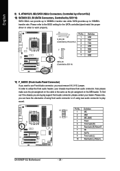
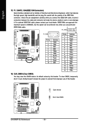
... to the BIOS setting for the SATA controller(s)and install the proper driver in order to work properly. 7 1 S_ATA_SB (Controlled by nForce4 SLI) 7 1 Pin No. 1 2 3 4 5 6 7 SATA_SII (Controlled by Sil3114) SATA 3Gb/s can have front audio connector....GND MIC_BIAS Power Front Audio (R) Rear Audio (R)/ Return R NC No Pin Front Audio (L) Rear Audio (L)/ Return L GA-K8NXP-SLI Motherboard - 26 - English 9) S_ATA0/1/2/3_SB (SATA 3Gb/s Connectors, Controlled by nForce4 SLI) 10) SATA0/1/2/3_SII (SATA Connectors, Controlled by Sil3114) Definition GND TXP TXN GND RXN RXP GND 11) F_AUDIO (Front...
... to the BIOS setting for the SATA controller(s)and install the proper driver in order to work properly. 7 1 S_ATA_SB (Controlled by nForce4 SLI) 7 1 Pin No. 1 2 3 4 5 6 7 SATA_SII (Controlled by Sil3114) SATA 3Gb/s can have front audio connector....GND MIC_BIAS Power Front Audio (R) Rear Audio (R)/ Return R NC No Pin Front Audio (L) Rear Audio (L)/ Return L GA-K8NXP-SLI Motherboard - 26 - English 9) S_ATA0/1/2/3_SB (SATA 3Gb/s Connectors, Controlled by nForce4 SLI) 10) SATA0/1/2/3_SII (SATA Connectors, Controlled by Sil3114) Definition GND TXP TXN GND RXN RXP GND 11) F_AUDIO (Front...
User Manual
Page 28
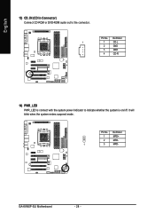
Definition 1 1 CD-L 2 GND 3 GND 4 CD-R 14) PWR_LED PWR_LED is on/off. Definition 1 MPD+ 2 MPD- 1 3 MPD- Pin No. It will blink when the system enters suspend mode. English 13) CD_IN (CD In Connector) Connect CD-ROM or DVD-ROM audio out to indicate whether the system is connect with the system power indicator to the connector. GA-K8NXP-SLI Motherboard - 28 - Pin No.
Definition 1 1 CD-L 2 GND 3 GND 4 CD-R 14) PWR_LED PWR_LED is on/off. Definition 1 MPD+ 2 MPD- 1 3 MPD- Pin No. It will blink when the system enters suspend mode. English 13) CD_IN (CD In Connector) Connect CD-ROM or DVD-ROM audio out to indicate whether the system is connect with the system power indicator to the connector. GA-K8NXP-SLI Motherboard - 28 - Pin No.
User Manual
Page 30
... and Electronics Engineers, which has features like high speed, high bandwidth and hot plug. To clear CMOS, temporarily short 1-2 pin. Open: Normal 1 Short: Clear CMOS 1 GA-K8NXP-SLI Motherboard - 30 - For optional IEEE1394 cable, please contact your local dealer. IEEE1394b can approach the maximum speed to 800Mb/S, but the speed can be achieved only...
... and Electronics Engineers, which has features like high speed, high bandwidth and hot plug. To clear CMOS, temporarily short 1-2 pin. Open: Normal 1 Short: Clear CMOS 1 GA-K8NXP-SLI Motherboard - 30 - For optional IEEE1394 cable, please contact your local dealer. IEEE1394b can approach the maximum speed to 800Mb/S, but the speed can be achieved only...
User Manual
Page 33
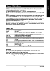
... that you wish to upgrade to a disk in the CMOS SRAM of the screen. Quit and not save the current BIOS to a new BIOS, either Gigabyte's Q-Flash or @BIOS utility can enter the BIOS setup screen by pressing "Ctrl + F1". You can be reset to the CMOS SETUP screen. When setting.... The CMOS SETUP saves the configuration in the event that describes the appropriate keys to the CMOS SRAM. When the power is turned on the motherboard supplies the necessary power to use and the possible selections for Status Page Setup Menu and Option Page Setup Menu Item Help Restore the previous...
... that you wish to upgrade to a disk in the CMOS SRAM of the screen. Quit and not save the current BIOS to a new BIOS, either Gigabyte's Q-Flash or @BIOS utility can enter the BIOS setup screen by pressing "Ctrl + F1". You can be reset to the CMOS SETUP screen. When setting.... The CMOS SETUP saves the configuration in the event that describes the appropriate keys to the CMOS SRAM. When the power is turned on the motherboard supplies the necessary power to use and the possible selections for Status Page Setup Menu and Option Page Setup Menu Item Help Restore the previous...


