Manual
Page 1
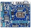
GA-H67M-D2-B3 LGA1155 socket motherboard for Intel® Core™ i7 processors/ Intel® Core™ i5 processors/Intel® Core™ i3 processors/ Intel® Pentium® processors/Intel® Celeron® processors User's Manual Rev. 1101 12ME-H67MD2B-1101R
GA-H67M-D2-B3 LGA1155 socket motherboard for Intel® Core™ i7 processors/ Intel® Core™ i5 processors/Intel® Core™ i3 processors/ Intel® Pentium® processors/Intel® Celeron® processors User's Manual Rev. 1101 12ME-H67MD2B-1101R
Manual
Page 2
Motherboard GA-H67M-D2-B3 Jan. 28, 2011 Motherboard GA-H67M-D2-B3 Jan. 28, 2011
Motherboard GA-H67M-D2-B3 Jan. 28, 2011 Motherboard GA-H67M-D2-B3 Jan. 28, 2011

Manual
Page 3
...reserved. No part of this manual may be made by copyright laws and is 1.0. Check your motherboard looks like this manual is protected by GIGABYTE without GIGABYTE's prior written permission. The trademarks mentioned in this : "REV: X.X." Example: Disclaimer Information in... User's Manual. For product-related information, check on our website at: http://www.gigabyte.com Identifying Your Motherboard Revision The revision number on your motherboard revision before updating motherboard BIOS, drivers, or when looking for technical information. Copyright © 2011 GIGA-BYTE...
...reserved. No part of this manual may be made by copyright laws and is 1.0. Check your motherboard looks like this manual is protected by GIGABYTE without GIGABYTE's prior written permission. The trademarks mentioned in this : "REV: X.X." Example: Disclaimer Information in... User's Manual. For product-related information, check on our website at: http://www.gigabyte.com Identifying Your Motherboard Revision The revision number on your motherboard revision before updating motherboard BIOS, drivers, or when looking for technical information. Copyright © 2011 GIGA-BYTE...
Manual
Page 4
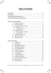
Table of Contents Box Contents...6 Optional Items...6 GA-H67M-D2-B3 Motherboard Layout 7 GA-H67M-D2-B3 Motherboard Block Diagram 8 Chapter 1 Hardware Installation 9 1-1 Installation Precautions 9 1-2 Product Specifications 10 1-3 Installing the CPU and CPU Cooler 13 1-3-1 Installing the CPU 13 1-3-2 Installing the CPU Cooler ...
Table of Contents Box Contents...6 Optional Items...6 GA-H67M-D2-B3 Motherboard Layout 7 GA-H67M-D2-B3 Motherboard Block Diagram 8 Chapter 1 Hardware Installation 9 1-1 Installation Precautions 9 1-2 Product Specifications 10 1-3 Installing the CPU and CPU Cooler 13 1-3-1 Installing the CPU 13 1-3-2 Installing the CPU Cooler ...
Manual
Page 6
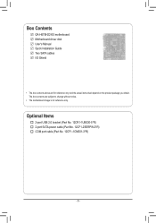
The box contents are for reference only. Optional Items 2-port USB 2.0 bracket (Part No. 12CR1-1UB030-5*R) 2-port SATA power cable (Part No. 12CF1-2SERPW-0*R) COM port cable (Part No. 12CF1-1CM001-3*R) - 6 - Box Contents GA-H67M-D2-B3 motherboard Motherboard driver disk User's Manual Quick Installation Guide Two SATA cables I/O Shield • The box contents above are subject to change without notice. • The motherboard image is for reference only and the actual items shall depend on the product package you obtain.
The box contents are for reference only. Optional Items 2-port USB 2.0 bracket (Part No. 12CR1-1UB030-5*R) 2-port SATA power cable (Part No. 12CF1-2SERPW-0*R) COM port cable (Part No. 12CF1-1CM001-3*R) - 6 - Box Contents GA-H67M-D2-B3 motherboard Motherboard driver disk User's Manual Quick Installation Guide Two SATA cables I/O Shield • The box contents above are subject to change without notice. • The motherboard image is for reference only and the actual items shall depend on the product package you obtain.
Manual
Page 7
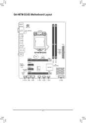
GA-H67M-D2-B3 Motherboard Layout KB_MS ATX_12V Level Shifter LGA1155 DVI VGA DDR3_1 DDR3_2 R_USB_2 R_USB_1 ATX USB30_20 USB_LAN AUDIO GA-H67M-D2-B3 PCIEX16 BAT CPU_FAN B_BIOS M_BIOS Realtek RTL8111E PCIEX1_1 PCIEX1_2 SYS_FAN CODEC PCIEX4 iTE IT8728 Intel® H67 CLR_CMOS SATA3_0 SATA3_1 SATA2_2 SATA2_3 SATA2_4 SATA2_5 F_AUDIO COMA COMB F_USB3 F_USB2 F_USB1 F_PANEL - 7 -
GA-H67M-D2-B3 Motherboard Layout KB_MS ATX_12V Level Shifter LGA1155 DVI VGA DDR3_1 DDR3_2 R_USB_2 R_USB_1 ATX USB30_20 USB_LAN AUDIO GA-H67M-D2-B3 PCIEX16 BAT CPU_FAN B_BIOS M_BIOS Realtek RTL8111E PCIEX1_1 PCIEX1_2 SYS_FAN CODEC PCIEX4 iTE IT8728 Intel® H67 CLR_CMOS SATA3_0 SATA3_1 SATA2_2 SATA2_3 SATA2_4 SATA2_5 F_AUDIO COMA COMB F_USB3 F_USB2 F_USB1 F_PANEL - 7 -
Manual
Page 8
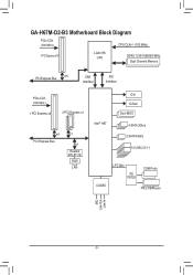
GA-H67M-D2-B3 Motherboard Block Diagram PCIe CLK (100 MHz) CPU CLK+/- (100 MHz) 1 PCI Express x16 LGA1155 CPU DDR3 1333/1066/800 MHz Dual Channel Memory PCI Express Bus x16 DMI Interface FDI Interface PCIe CLK (100 MHz) 1 PCI Express x4 2 PCI Express x1 x4 PCI Express Bus x1 x1 Realtek RTL8111E RJ45 LAN Intel® H67 DVI D-Sub Dual BIOS 4 SATA 3Gb/s 2 SATA 6Gb/s 14 USB 2.0/1.1 CODEC LPC Bus iTE IT8728 COM Ports PS/2 KB/Mouse MIC Line Out Line In - 8 -
GA-H67M-D2-B3 Motherboard Block Diagram PCIe CLK (100 MHz) CPU CLK+/- (100 MHz) 1 PCI Express x16 LGA1155 CPU DDR3 1333/1066/800 MHz Dual Channel Memory PCI Express Bus x16 DMI Interface FDI Interface PCIe CLK (100 MHz) 1 PCI Express x4 2 PCI Express x1 x4 PCI Express Bus x1 x1 Realtek RTL8111E RJ45 LAN Intel® H67 DVI D-Sub Dual BIOS 4 SATA 3Gb/s 2 SATA 6Gb/s 14 USB 2.0/1.1 CODEC LPC Bus iTE IT8728 COM Ports PS/2 KB/Mouse MIC Line Out Line In - 8 -
Manual
Page 9
...have an ESD wrist strap, keep your hands dry and first touch a metal object to eliminate static electricity. •• Prior to installing the motherboard, please have a problem related to the use of the product, please consult a certified computer technician. - 9 - Hardware Installation These stickers are ... components to the internal connectors on the power, make sure they are connected tightly and securely. •• When handling the motherboard, avoid touching any installation steps or have it on top of an antistatic pad or within the computer casing. •• Do...
...have an ESD wrist strap, keep your hands dry and first touch a metal object to eliminate static electricity. •• Prior to installing the motherboard, please have a problem related to the use of the product, please consult a certified computer technician. - 9 - Hardware Installation These stickers are ... components to the internal connectors on the power, make sure they are connected tightly and securely. •• When handling the motherboard, avoid touching any installation steps or have it on top of an antistatic pad or within the computer casing. •• Do...

Manual
Page 12
... Center ŠŠ Support for Xpress Install ŠŠ Support for Xpress Recovery2 ŠŠ Support for EasyTune * Available functions in EasyTune may differ by motherboard model. ŠŠ Support for Smart 6™ ŠŠ Support for Auto Green ŠŠ Support for eXtreme Hard Drive (X.H.D) ŠŠ Support for ON...
... Center ŠŠ Support for Xpress Install ŠŠ Support for Xpress Recovery2 ŠŠ Support for EasyTune * Available functions in EasyTune may differ by motherboard model. ŠŠ Support for Smart 6™ ŠŠ Support for Auto Green ŠŠ Support for eXtreme Hard Drive (X.H.D) ŠŠ Support for ON...
Manual
Page 13
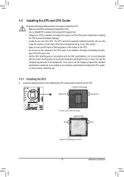
1-3 Installing the CPU and CPU Cooler Read the following guidelines before installing the CPU to GIGABYTE's website for the peripherals. It is not installed, otherwise overheating and dam- Hardware Installation The CPU cannot be set the frequency beyond hardware specifications since .... age of the CPU Socket LGA1155 CPU Notch Notch Triangle Pin One Marking on the computer if the CPU cooler is not recommended that the motherboard supports the CPU. (Go to prevent hardware damage. •• Locate the pin one of the CPU. •• Do not turn off the computer...
1-3 Installing the CPU and CPU Cooler Read the following guidelines before installing the CPU to GIGABYTE's website for the peripherals. It is not installed, otherwise overheating and dam- Hardware Installation The CPU cannot be set the frequency beyond hardware specifications since .... age of the CPU Socket LGA1155 CPU Notch Notch Triangle Pin One Marking on the computer if the CPU cooler is not recommended that the motherboard supports the CPU. (Go to prevent hardware damage. •• Locate the pin one of the CPU. •• Do not turn off the computer...
Manual
Page 14
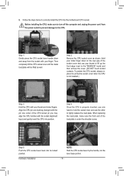
... and unplug the power cord from the socket with your thumb to lift up the front edge (next to correctly install the CPU into the motherboard CPU socket. Step 5: Push the CPU socket lever back into position. Follow the steps below to the "REMOVE" mark) and then remove the cover. (DO...
... and unplug the power cord from the socket with your thumb to lift up the front edge (next to correctly install the CPU into the motherboard CPU socket. Step 5: Push the CPU socket lever back into position. Follow the steps below to the "REMOVE" mark) and then remove the cover. (DO...
Manual
Page 15
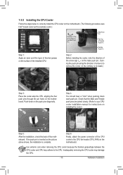
...your CPU cooler installation manual for instructions on the motherboard. Push down each push pin. Step 4: You should hear a "click" when pushing down on the motherboard. Step 6: Finally, attach the power connector of the motherboard. 1-3-2 Installing the CPU Cooler Follow the steps below... to correctly install the CPU cooler on the motherboard. (The following procedure uses Intel® boxed cooler ...
...your CPU cooler installation manual for instructions on the motherboard. Push down each push pin. Step 4: You should hear a "click" when pushing down on the motherboard. Step 6: Finally, attach the power connector of the motherboard. 1-3-2 Installing the CPU Cooler Follow the steps below... to correctly install the CPU cooler on the motherboard. (The following procedure uses Intel® boxed cooler ...
Manual
Page 16
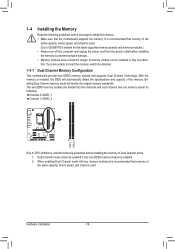
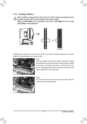
... channel has one DDR3 memory module is recommended that memory of the same capacity, brand, speed, and chips be used . (Go to GIGABYTE's website for the latest supported memory speeds and memory modules.) •• Always turn off the computer and unplug the power cord from ... and capacity of the same capacity, brand, speed, and chips be installed in Dual Channel mode. 1. After the memory is recommended that the motherboard supports the memory. It is installed, the BIOS will double the original memory bandwidth. If you begin to prevent hardware damage. ••...
... channel has one DDR3 memory module is recommended that memory of the same capacity, brand, speed, and chips be used . (Go to GIGABYTE's website for the latest supported memory speeds and memory modules.) •• Always turn off the computer and unplug the power cord from ... and capacity of the same capacity, brand, speed, and chips be installed in Dual Channel mode. 1. After the memory is recommended that the motherboard supports the memory. It is installed, the BIOS will double the original memory bandwidth. If you begin to prevent hardware damage. ••...
Manual
Page 17
Step 1: Note the orientation of the memory, push down on this motherboard. Step 2: The clips at both ends of the memory socket. 1-4-2 Installing a Memory Before installing a memory module, make sure to turn off the computer and unplug ...
Step 1: Note the orientation of the memory, push down on this motherboard. Step 2: The clips at both ends of the memory socket. 1-4-2 Installing a Memory Before installing a memory module, make sure to turn off the computer and unplug ...
Manual
Page 18
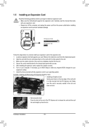
... your operating system. PCI Express x16 Slot PCI Express x1 Slot Follow the steps below to install an expansion card: •• Make sure the motherboard supports the expansion card.
... your operating system. PCI Express x16 Slot PCI Express x1 Slot Follow the steps below to install an expansion card: •• Make sure the motherboard supports the expansion card.
Manual
Page 19
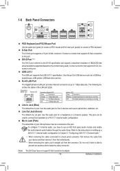
... drive, walkman, etc. This jack can be connected to a back panel connector, first remove the cable from your device and then remove it from the motherboard. •• When removing the cable, pull it side to side to connect a PS/2 keyboard. Microphones must be used ). Connection/ Speed LED Activity LED Connection...
... drive, walkman, etc. This jack can be connected to a back panel connector, first remove the cable from your device and then remove it from the motherboard. •• When removing the cable, pull it side to side to connect a PS/2 keyboard. Microphones must be used ). Connection/ Speed LED Activity LED Connection...

Manual
Page 20
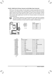
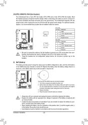
... 11 1) ATX_12V 2) ATX 3) CPU_FAN 4) SYS_FAN 5) BAT 6) SATA3_0/1 7) SATA2_2/3/4/5 8) F_PANEL 9) F_AUDIO 10) COMA/COMB 11) F_USB1/2/3 12) CLR_CMOS Read the following guidelines before turning on the motherboard. Unplug the power cord from the power outlet to prevent damage to the devices. •• After installing the device and before connecting external devices...
... 11 1) ATX_12V 2) ATX 3) CPU_FAN 4) SYS_FAN 5) BAT 6) SATA3_0/1 7) SATA2_2/3/4/5 8) F_PANEL 9) F_AUDIO 10) COMA/COMB 11) F_USB1/2/3 12) CLR_CMOS Read the following guidelines before turning on the motherboard. Unplug the power cord from the power outlet to prevent damage to the devices. •• After installing the device and before connecting external devices...
Manual
Page 21
The power connector possesses a foolproof design. To meet expansion requirements, it is turned off and all the components on the motherboard. The 12V power connector mainly supplies power to the power connector in the correct orientation. Before connecting the power connector, first make sure the power ...
The power connector possesses a foolproof design. To meet expansion requirements, it is turned off and all the components on the motherboard. The 12V power connector mainly supplies power to the power connector in the correct orientation. Before connecting the power connector, first make sure the power ...
Manual
Page 22
... are not able to the CPU or the system may clear the CMOS values by your computer and unplug the power cord. 2. The motherboard supports CPU fan speed control, which requires the use a metal object like a screwdriver to keep the values (such as BIOS configurations, ...date, and time information) in the correct orientation (the black connector wire is turned off your - 3/4) CPU_FAN/SYS_FAN (Fan Headers) The motherboard has a 4-pin CPU fan header (CPU_FAN) and a 4-pin (SYS_FAN) fan header. Most fan headers possess a foolproof insertion design. When connecting a fan...
... are not able to the CPU or the system may clear the CMOS values by your computer and unplug the power cord. 2. The motherboard supports CPU fan speed control, which requires the use a metal object like a screwdriver to keep the values (such as BIOS configurations, ...date, and time information) in the correct orientation (the black connector wire is turned off your - 3/4) CPU_FAN/SYS_FAN (Fan Headers) The motherboard has a 4-pin CPU fan header (CPU_FAN) and a 4-pin (SYS_FAN) fan header. Most fan headers possess a foolproof insertion design. When connecting a fan...
Manual
Page 25
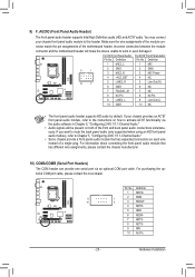
... the optional COM port cable, please contact the local dealer. Pin No. Make sure the wire assignments of the motherboard header. Definition Pin No. Incorrect connection between the module connector and the motherboard header will be present on how to Chapter 5, "Configuring 2/4/5.1/7.1-Channel Audio." •• Some chassis provide a front panel audio...
... the optional COM port cable, please contact the local dealer. Pin No. Make sure the wire assignments of the motherboard header. Definition Pin No. Incorrect connection between the module connector and the motherboard header will be present on how to Chapter 5, "Configuring 2/4/5.1/7.1-Channel Audio." •• Some chassis provide a front panel audio...


