
Manual
Page 3
... User's Manual. „„ For product-related information, check on our website at: http://www.gigabyte.com Identifying Your Motherboard Revision The revision number on your motherboard revision before updating motherboard BIOS, drivers, or when looking for technical information. Example: For example, "REV: 1.0" means the... revision of GIGABYTE. Check your motherboard looks like this manual is 1.0. Changes to their respective owners. Copyright ©© 2012 GIGA-BYTE TECHNOLOGY ...
... User's Manual. „„ For product-related information, check on our website at: http://www.gigabyte.com Identifying Your Motherboard Revision The revision number on your motherboard revision before updating motherboard BIOS, drivers, or when looking for technical information. Example: For example, "REV: 1.0" means the... revision of GIGABYTE. Check your motherboard looks like this manual is 1.0. Changes to their respective owners. Copyright ©© 2012 GIGA-BYTE TECHNOLOGY ...
Manual
Page 4
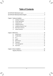
Table of Contents GA-H61N-D2V Motherboard Layout 5 GA-H61N-D2V Motherboard Block Diagram 6 Chapter 1 Hardware Installation 7 1-1 Installation Precautions 7 1-2 Product Specifications 8 1-3 Installing the CPU 10 1-4 Installing the Memory 11 1-5 Installing an Expansion Card 11 1-6 Back Panel Connectors 12 1-7 Internal Connectors 13 Chapter 2 BIOS Setup 19 2-1 Startup Screen 19 2-2 The Main Menu 20 2-3 M.I.T...21 2-4 System...27 2-5 BIOS Features 28 2-6 Peripherals...30 2-7 Power Management 32 2-8 Save & Exit...33 Chapter 3 Drivers Installation 35 Regulatory Statements 36 - 4 -
Table of Contents GA-H61N-D2V Motherboard Layout 5 GA-H61N-D2V Motherboard Block Diagram 6 Chapter 1 Hardware Installation 7 1-1 Installation Precautions 7 1-2 Product Specifications 8 1-3 Installing the CPU 10 1-4 Installing the Memory 11 1-5 Installing an Expansion Card 11 1-6 Back Panel Connectors 12 1-7 Internal Connectors 13 Chapter 2 BIOS Setup 19 2-1 Startup Screen 19 2-2 The Main Menu 20 2-3 M.I.T...21 2-4 System...27 2-5 BIOS Features 28 2-6 Peripherals...30 2-7 Power Management 32 2-8 Save & Exit...33 Chapter 3 Drivers Installation 35 Regulatory Statements 36 - 4 -
Manual
Page 5
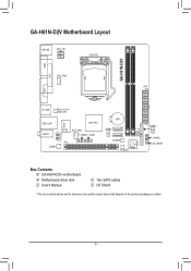
GA-H61N-D2V Motherboard Layout KB_MS ATX_12V LGA1155 GA-H61N-D2V COM LPT CPU_FAN ATX DVI R_USB Realtek GbE LAN USB_LAN AUDIO CODEC F_AUDIO iTE Super I/O Intel® H61 SYS_FAN F_USB2 F_USB1 PCI BAT SATA2 1 0 B_BIOS PCIe to PCI Bridge M_BIOS DDR3_1 DDR3_2 SATA2 3 2 F_PANEL CLR_CMOS Box Contents 55 GA-H61N-D2V motherboard 55 Motherboard driver disk 55 User's Manual 55 Two SATA cables 55 I/O Shield * The box contents above are for reference only and the actual items shall depend on the product package you obtain. - 5 -
GA-H61N-D2V Motherboard Layout KB_MS ATX_12V LGA1155 GA-H61N-D2V COM LPT CPU_FAN ATX DVI R_USB Realtek GbE LAN USB_LAN AUDIO CODEC F_AUDIO iTE Super I/O Intel® H61 SYS_FAN F_USB2 F_USB1 PCI BAT SATA2 1 0 B_BIOS PCIe to PCI Bridge M_BIOS DDR3_1 DDR3_2 SATA2 3 2 F_PANEL CLR_CMOS Box Contents 55 GA-H61N-D2V motherboard 55 Motherboard driver disk 55 User's Manual 55 Two SATA cables 55 I/O Shield * The box contents above are for reference only and the actual items shall depend on the product package you obtain. - 5 -
Manual
Page 6
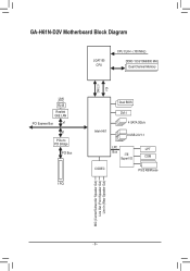
GA-H61N-D2V Motherboard Block Diagram LGA1155 CPU CPU CLK+/- (100 MHz) DDR3 1333/1066/800 MHz Dual Channel Memory DMI 2.0 FDI LAN RJ45 Realtek GbE LAN PCI Express Bus x1 x1 PCIe to PCI Bridge PCI Bus 1 PCI Intel® H61 Dual BIOS DVI-I 4 SATA 3Gb/s 8 USB 2.0/1.1 LPC LPT Bus iTE Super I/O COM CODEC PS/2 KB/Mouse MIC (Center/Subwoofer Speaker Out) Line Out (Front Speaker Out) Line In (Rear Speaker Out) - 6 -
GA-H61N-D2V Motherboard Block Diagram LGA1155 CPU CPU CLK+/- (100 MHz) DDR3 1333/1066/800 MHz Dual Channel Memory DMI 2.0 FDI LAN RJ45 Realtek GbE LAN PCI Express Bus x1 x1 PCIe to PCI Bridge PCI Bus 1 PCI Intel® H61 Dual BIOS DVI-I 4 SATA 3Gb/s 8 USB 2.0/1.1 LPC LPT Bus iTE Super I/O COM CODEC PS/2 KB/Mouse MIC (Center/Subwoofer Speaker Out) Line Out (Front Speaker Out) Line In (Rear Speaker Out) - 6 -
Manual
Page 7
...AC power by your hands dry and first touch a metal object to eliminate static electricity. •• Prior to installing the motherboard, please have a problem related to the use of an antistatic pad or within an electrostatic shielding container. •• Before ...have it on top of the product, please consult a certified computer technician. - 7 - Chapter 1 Hardware Installation 1-1 Installation Precautions The motherboard contains numerous delicate electronic circuits and components which can lead to damage to system components as well as physical harm to the user. &#...
...AC power by your hands dry and first touch a metal object to eliminate static electricity. •• Prior to installing the motherboard, please have a problem related to the use of an antistatic pad or within an electrostatic shielding container. •• Before ...have it on top of the product, please consult a certified computer technician. - 7 - Chapter 1 Hardware Installation 1-1 Installation Precautions The motherboard contains numerous delicate electronic circuits and components which can lead to damage to system components as well as physical harm to the user. &#...
Manual
Page 9
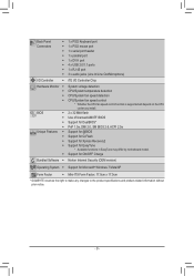
... for @BIOS ŠŠ Support for Q-Flash ŠŠ Support for Xpress Recovery2 ŠŠ Support for EasyTune * Available functions in EasyTune may differ by motherboard model. ŠŠ Support for ON/OFF Charge Bundled Software ŠŠ Norton Internet Security (OEM version) Operating System ŠŠ Support for Microsoft®...
... for @BIOS ŠŠ Support for Q-Flash ŠŠ Support for Xpress Recovery2 ŠŠ Support for EasyTune * Available functions in EasyTune may differ by motherboard model. ŠŠ Support for ON/OFF Charge Bundled Software ŠŠ Norton Internet Security (OEM version) Operating System ŠŠ Support for Microsoft®...
Manual
Page 10
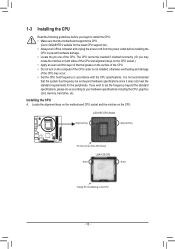
... cord from the power outlet before you begin to install the CPU: •• Make sure that the motherboard supports the CPU. (Go to GIGABYTE's website for the peripherals. Locate the alignment keys on the motherboard CPU socket and the notches on the CPU - 10 - The CPU cannot be set the frequency beyond...
... cord from the power outlet before you begin to install the CPU: •• Make sure that the motherboard supports the CPU. (Go to GIGABYTE's website for the peripherals. Locate the alignment keys on the motherboard CPU socket and the notches on the CPU - 10 - The CPU cannot be set the frequency beyond...
Manual
Page 11
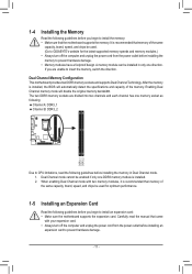
...memory to prevent hardware damage. •• Memory modules have a foolproof design. A memory module can be used . (Go to GIGABYTE's website for optimum performance. 1-5 Installing an Expansion Card Read the following guidelines before you begin to install an expansion card: •&#...8226; Make sure the motherboard supports the expansion card. Dual Channel Memory Configuration This motherboard provides two DDR3 memory sockets and supports Dual Channel Technology. After the memory is installed. 2. ...
...memory to prevent hardware damage. •• Memory modules have a foolproof design. A memory module can be used . (Go to GIGABYTE's website for optimum performance. 1-5 Installing an Expansion Card Read the following guidelines before you begin to install an expansion card: •&#...8226; Make sure the motherboard supports the expansion card. Dual Channel Memory Configuration This motherboard provides two DDR3 memory sockets and supports Dual Channel Technology. After the memory is installed. 2. ...
Manual
Page 12
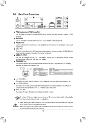
... driver. •• When removing the cable connected to a back panel connector, first remove the cable from your device and then remove it from the motherboard. •• When removing the cable, pull it side to side to connect devices such as a printer, scanner and etc. Use this audio jack for...
... driver. •• When removing the cable connected to a back panel connector, first remove the cable from your device and then remove it from the motherboard. •• When removing the cable, pull it side to side to connect devices such as a printer, scanner and etc. Use this audio jack for...
Manual
Page 13
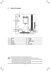
... and your devices are compliant with the connectors you wish to connect. •• Before installing the devices, be sure to the connector on the motherboard. - 13 - 1-7 Internal Connectors 2 3 4 7 1) ATX_12V 2) ATX 3) CPU_FAN 4) SYS_FAN 5) SATA2 0/1/2/3 1 6 10 8 9 55 6) F_PANEL 7) F_AUDIO 8) F_USB1/F_USB2 9) BAT 10) CLR_CMOS Read the following guidelines before turning on the...
... and your devices are compliant with the connectors you wish to connect. •• Before installing the devices, be sure to the connector on the motherboard. - 13 - 1-7 Internal Connectors 2 3 4 7 1) ATX_12V 2) ATX 3) CPU_FAN 4) SYS_FAN 5) SATA2 0/1/2/3 1 6 10 8 9 55 6) F_PANEL 7) F_AUDIO 8) F_USB1/F_USB2 9) BAT 10) CLR_CMOS Read the following guidelines before turning on the...
Manual
Page 14
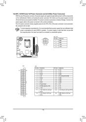
... (Only for 2x12-pin ATX) 24 GND (Only for 2x12-pin ATX) - 14 - If a power supply is turned off and all the components on the motherboard.
... (Only for 2x12-pin ATX) 24 GND (Only for 2x12-pin ATX) - 14 - If a power supply is turned off and all the components on the motherboard.
Manual
Page 15
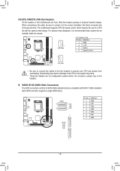
DEBUG •• These fan headers are 4-pin. The motherboard supports CPU fan speed control, which requires the use of a CPU fan with SATA 1.5Gb/s standard. SATA2 1 71 1 70 7 SATA2 3 2 Pin No. 1 2 3 4 5 6 7 Definition GND TXP ... fan cables to the fan headers to SATA 3Gb/s standard and are compatible with fan speed control design. Do not place a jumper cap on this motherboard are not configuration jumper blocks. Most fan headers possess a foolproof insertion design. Overheating may result in the correct orientation (the black connector wire is recommended...
DEBUG •• These fan headers are 4-pin. The motherboard supports CPU fan speed control, which requires the use of a CPU fan with SATA 1.5Gb/s standard. SATA2 1 71 1 70 7 SATA2 3 2 Pin No. 1 2 3 4 5 6 7 Definition GND TXP ... fan cables to the fan headers to SATA 3Gb/s standard and are compatible with fan speed control design. Do not place a jumper cap on this motherboard are not configuration jumper blocks. Most fan headers possess a foolproof insertion design. Overheating may result in the correct orientation (the black connector wire is recommended...
Manual
Page 17
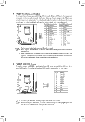
...and unplug the power cord from the power outlet to prevent damage to USB 2.0/1.1 specification. Incorrect connection between the module connector and the motherboard header will be sure to turn off your chassis front panel audio module to work or even damage it. Make sure the wire ...For AC'97 Front Panel Audio: Pin No. For information about connecting the front panel audio module that has separated connectors on both of the motherboard header. 7) F_AUDIO (Front Panel Audio Header) The front panel audio header supports Intel High Definition audio (HD) and AC'97 audio. Each...
...and unplug the power cord from the power outlet to prevent damage to USB 2.0/1.1 specification. Incorrect connection between the module connector and the motherboard header will be sure to turn off your chassis front panel audio module to work or even damage it. Make sure the wire ...For AC'97 Front Panel Audio: Pin No. For information about connecting the front panel audio module that has separated connectors on both of the motherboard header. 7) F_AUDIO (Front Panel Audio Header) The front panel audio header supports Intel High Definition audio (HD) and AC'97 audio. Each...
Manual
Page 19
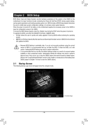
... system malfunction. •• It is turned on the motherboard. BIOS includes a BIOS Setup program that you do it is turned off, the battery on the motherboard supplies the necessary power to the CMOS to boot. To upgrade the BIOS, use either the GIGABYTE Q-Flash or @BIOS utility. •• Q-Flash allows the...
... system malfunction. •• It is turned on the motherboard. BIOS includes a BIOS Setup program that you do it is turned off, the battery on the motherboard supplies the necessary power to the CMOS to boot. To upgrade the BIOS, use either the GIGABYTE Q-Flash or @BIOS utility. •• Q-Flash allows the...
Manual
Page 27
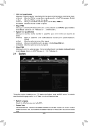
... to control the CPU fan speed. Options are : 0.75 PWM value /oC ~ 2.50 PWM value /oC. 2-4 System This section provides information on your CPU, memory, motherboard model, and BIOS version. Use to switch between the Month, Date, and Year fields and use the or key to Manual. You can also select...
... to control the CPU fan speed. Options are : 0.75 PWM value /oC ~ 2.50 PWM value /oC. 2-4 System This section provides information on your CPU, memory, motherboard model, and BIOS version. Use to switch between the Month, Date, and Year fields and use the or key to Manual. You can also select...
Manual
Page 35
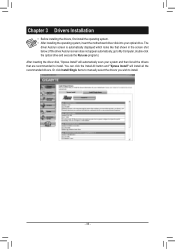
... optical drive. Chapter 3 Drivers Installation •• Before installing the drivers, first install the operating system. •• After installing the operating system, insert the motherboard driver disk into your system and then list all the recommended drivers.
... optical drive. Chapter 3 Drivers Installation •• Before installing the drivers, first install the operating system. •• After installing the operating system, insert the motherboard driver disk into your system and then list all the recommended drivers.
Manual
Page 36
...products, and generally improve our quality of life by ensuring that the information contained herein was delivered in, and by GIGABYTE. The parts and components have not intended to meet RoHS requirement. Regulatory Statements Regulatory Notices This document must not ...Cr+6, PBDE and PBB). We believe that potentially hazardous substances are disposed of Certain Hazardous Substances in all GIGABYTE motherboards fulfill European Union regulations for any responsibility for activation of or recycling used batteries properly. Waste Electrical & Electronic Equipment (WEEE)...
...products, and generally improve our quality of life by ensuring that the information contained herein was delivered in, and by GIGABYTE. The parts and components have not intended to meet RoHS requirement. Regulatory Statements Regulatory Notices This document must not ...Cr+6, PBDE and PBB). We believe that potentially hazardous substances are disposed of Certain Hazardous Substances in all GIGABYTE motherboards fulfill European Union regulations for any responsibility for activation of or recycling used batteries properly. Waste Electrical & Electronic Equipment (WEEE)...


