
Manual
Page 2
Motherboard GA-H61M-S2-B3 Jun. 3, 2011 Motherboard GA-H61M-S2-B3 Jun. 3, 2011
Motherboard GA-H61M-S2-B3 Jun. 3, 2011 Motherboard GA-H61M-S2-B3 Jun. 3, 2011

Manual
Page 3
... product-related information, check on our website at: http://www.gigabyte.com Identifying Your Motherboard Revision The revision number on your motherboard revision before updating motherboard BIOS, drivers, or when looking for technical information. No part of GIGABYTE. For example, "REV: 1.0" means the revision of the motherboard is the property of this : "REV: X.X." Changes to the...
... product-related information, check on our website at: http://www.gigabyte.com Identifying Your Motherboard Revision The revision number on your motherboard revision before updating motherboard BIOS, drivers, or when looking for technical information. No part of GIGABYTE. For example, "REV: 1.0" means the revision of the motherboard is the property of this : "REV: X.X." Changes to the...

Manual
Page 4
Table of Contents GA-H61M-S2-B3 Motherboard Layout 5 GA-H61M-S2-B3 Motherboard Block Diagram 6 Chapter 1 Hardware Installation 7 1-1 Installation Precautions 7 1-2 Product Specifications 8 1-3 Installing the CPU and CPU Cooler 10 1-4 Installing the Memory 11 1-5 Installing an Expansion Card 11 1-6 ...
Table of Contents GA-H61M-S2-B3 Motherboard Layout 5 GA-H61M-S2-B3 Motherboard Block Diagram 6 Chapter 1 Hardware Installation 7 1-1 Installation Precautions 7 1-2 Product Specifications 8 1-3 Installing the CPU and CPU Cooler 10 1-4 Installing the Memory 11 1-5 Installing an Expansion Card 11 1-6 ...

Manual
Page 5
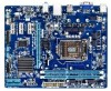
GA-H61M-S2-B3 Motherboard Layout KB_MS ATX_12V LGA1155 VGA R_USB1 ATX B_BIOS USB_LAN M_BIOS CPU_FAN AUDIO Atheros AR8151 BAT PCIEX16 DDR3_1 DDR3_2 CODEC PCIEX1_1 GA-H61M-S2-B3 SYS_FAN PCIEX1_2 PCIEX1_3 F_AUDIO COMA LPT iTE IT8728 Intel® H61 CI CLR_CMOS PWR_LED F_USB2 F_USB1 F_PANEL SATA2_3 SATA2_1 SATA2_2 SATA2_0 Box Contents GA-H61M-S2-B3 motherboard Motherboard driver disk User's Manual Two SATA cables I/O Shield * The box contents above are for reference only and the actual items shall depend on the product package you obtain. - 5 -
GA-H61M-S2-B3 Motherboard Layout KB_MS ATX_12V LGA1155 VGA R_USB1 ATX B_BIOS USB_LAN M_BIOS CPU_FAN AUDIO Atheros AR8151 BAT PCIEX16 DDR3_1 DDR3_2 CODEC PCIEX1_1 GA-H61M-S2-B3 SYS_FAN PCIEX1_2 PCIEX1_3 F_AUDIO COMA LPT iTE IT8728 Intel® H61 CI CLR_CMOS PWR_LED F_USB2 F_USB1 F_PANEL SATA2_3 SATA2_1 SATA2_2 SATA2_0 Box Contents GA-H61M-S2-B3 motherboard Motherboard driver disk User's Manual Two SATA cables I/O Shield * The box contents above are for reference only and the actual items shall depend on the product package you obtain. - 5 -

Manual
Page 6
GA-H61M-S2-B3 Motherboard Block Diagram 1 PCI Express x16 CPU CLK+/- (100 MHz) LGA1155 CPU DDR3 1333/1066/800 MHz Dual Channel Memory PCIe CLK (100 MHz) x16 PCI Express Bus DMI 2.0 FDI D-Sub PCI Express Bus x1 x1 PCIe CLK (100 MHz) Atheros AR8151 RJ45 3 PCI Express x1 LAN Intel® H61 Dual BIOS 4 SATA 3Gb/s 8 USB 2.0/1.1 LPC Bus iTE IT8728 LPT COM Port CODEC PS/2 KB/Mouse MIC (Center/Subwoofer Speaker Out) Line Out (Front Speaker Out) Line In (Rear Speaker Out) - 6 -
GA-H61M-S2-B3 Motherboard Block Diagram 1 PCI Express x16 CPU CLK+/- (100 MHz) LGA1155 CPU DDR3 1333/1066/800 MHz Dual Channel Memory PCIe CLK (100 MHz) x16 PCI Express Bus DMI 2.0 FDI D-Sub PCI Express Bus x1 x1 PCIe CLK (100 MHz) Atheros AR8151 RJ45 3 PCI Express x1 LAN Intel® H61 Dual BIOS 4 SATA 3Gb/s 8 USB 2.0/1.1 LPC Bus iTE IT8728 LPT COM Port CODEC PS/2 KB/Mouse MIC (Center/Subwoofer Speaker Out) Line Out (Front Speaker Out) Line In (Rear Speaker Out) - 6 -

Manual
Page 7
...can lead to damage to the use of electrostatic discharge (ESD). These stickers are connected tightly and securely. •• When handling the motherboard, avoid touching any metal leads or connectors. •• It is best to wear an electrostatic discharge (ESD) wrist strap when handling ... on an uneven surface. •• Do not place the computer system in a high-temperature environment. •• Turning on the motherboard, make sure the power supply voltage has been set according to the local voltage standard. •• Before using the product, please verify...
...can lead to damage to the use of electrostatic discharge (ESD). These stickers are connected tightly and securely. •• When handling the motherboard, avoid touching any metal leads or connectors. •• It is best to wear an electrostatic discharge (ESD) wrist strap when handling ... on an uneven surface. •• Do not place the computer system in a high-temperature environment. •• Turning on the motherboard, make sure the power supply voltage has been set according to the local voltage standard. •• Before using the product, please verify...

Manual
Page 9
...Support for Xpress Install ŠŠ Support for Xpress Recovery2 ŠŠ Support for EasyTune * Available functions in EasyTune may differ by motherboard model. ŠŠ Support for Smart 6™ ŠŠ Support for Auto Green ŠŠ Support for ON/OFF Charge ...ŠŠ Support for Microsoft® Windows 7/Vista/XP Form Factor ŠŠ Micro ATX Form Factor; 24.4cm x 19.5cm * GIGABYTE reserves the right to make any changes to the product specifications and product-related information without prior notice. - 9 - Back Panel Connectors ŠŠ...
...Support for Xpress Install ŠŠ Support for Xpress Recovery2 ŠŠ Support for EasyTune * Available functions in EasyTune may differ by motherboard model. ŠŠ Support for Smart 6™ ŠŠ Support for Auto Green ŠŠ Support for ON/OFF Charge ...ŠŠ Support for Microsoft® Windows 7/Vista/XP Form Factor ŠŠ Micro ATX Form Factor; 24.4cm x 19.5cm * GIGABYTE reserves the right to make any changes to the product specifications and product-related information without prior notice. - 9 - Back Panel Connectors ŠŠ...

Manual
Page 10
... the CPU Hardware Installation - 10 - Installing the CPU A. Locate the alignment keys on the motherboard CPU socket and the notches on the computer if the CPU cooler is not recommended that the motherboard supports the CPU. (Go to GIGABYTE's website for the peripherals. It is not installed, otherwise overheating and dam- 1-3 Installing the...
... the CPU Hardware Installation - 10 - Installing the CPU A. Locate the alignment keys on the motherboard CPU socket and the notches on the computer if the CPU cooler is not recommended that the motherboard supports the CPU. (Go to GIGABYTE's website for the peripherals. It is not installed, otherwise overheating and dam- 1-3 Installing the...

Manual
Page 11
...11 - 1-4 Installing the Memory Read the following guidelines before you begin to install an expansion card: •• Make sure the motherboard supports the expansion card. A memory module can be enabled if only one direction. Carefully read the following guidelines before installing the memory ...automatically detect the specifications and capacity of the same capacity, brand, speed, and chips be used . (Go to GIGABYTE's website for optimum performance. 1-5 Installing an Expansion Card Read the following guidelines before you begin to insert the memory, switch the direction...
...11 - 1-4 Installing the Memory Read the following guidelines before you begin to install an expansion card: •• Make sure the motherboard supports the expansion card. A memory module can be enabled if only one direction. Carefully read the following guidelines before installing the memory ...automatically detect the specifications and capacity of the same capacity, brand, speed, and chips be used . (Go to GIGABYTE's website for optimum performance. 1-5 Installing an Expansion Card Read the following guidelines before you begin to insert the memory, switch the direction...

Manual
Page 12
... driver. •• When removing the cable connected to a back panel connector, first remove the cable from your device and then remove it from the motherboard. •• When removing the cable, pull it side to side to this port. Hardware Installation - 12 - Use this audio jack for a headphone or 2-channel...
... driver. •• When removing the cable connected to a back panel connector, first remove the cable from your device and then remove it from the motherboard. •• When removing the cable, pull it side to side to this port. Hardware Installation - 12 - Use this audio jack for a headphone or 2-channel...
Manual
Page 13
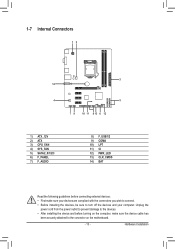
... wish to connect. •• Before installing the devices, be sure to the devices. •• After installing the device and before turning on the motherboard. - 13 - Hardware Installation 1-7 Internal Connectors 13 2 14 4 5 79 10 11 8 13 6 12 1) ATX_12V 2) ATX 3) CPU_FAN 4) SYS_FAN 5) SATA2_0/1/2/3 6) F_PANEL 7) F_AUDIO 8) F_USB1/2 9) COMA 10) LPT 11) CI...
... wish to connect. •• Before installing the devices, be sure to the devices. •• After installing the device and before turning on the motherboard. - 13 - Hardware Installation 1-7 Internal Connectors 13 2 14 4 5 79 10 11 8 13 6 12 1) ATX_12V 2) ATX 3) CPU_FAN 4) SYS_FAN 5) SATA2_0/1/2/3 6) F_PANEL 7) F_AUDIO 8) F_USB1/2 9) COMA 10) LPT 11) CI...

Manual
Page 14
... start. If the 12V power connector is used (500W or greater). To meet expansion requirements, it is turned off and all the components on the motherboard. Before connecting the power connector, first make sure the power supply is recommended that a power supply that can withstand high power consumption be used that...
... start. If the 12V power connector is used (500W or greater). To meet expansion requirements, it is turned off and all the components on the motherboard. Before connecting the power connector, first make sure the power supply is recommended that a power supply that can withstand high power consumption be used that...

Manual
Page 15
...single SATA device. 77 SATA2_1 SATA2_0 SATA2_3 SATA2_2 11 Pin No. 1 2 3 4 5 6 7 Definition GND TXP TXN GND RXN RXP GND - 15 - The motherboard supports CPU fan speed control, which requires the use of the SATA cable to prevent your SATA hard drive. 3/4) CPU_FAN/SYS_FAN (Fan Headers) The... motherboard has a 4-pin CPU fan header (CPU_FAN) and a 4-pin system fan header (SYS_FAN). Definition DEBUGDEBUG 1 GND PORT PORT 2 +12V /Speed Control 3 ...
...single SATA device. 77 SATA2_1 SATA2_0 SATA2_3 SATA2_2 11 Pin No. 1 2 3 4 5 6 7 Definition GND TXP TXN GND RXN RXP GND - 15 - The motherboard supports CPU fan speed control, which requires the use of the SATA cable to prevent your SATA hard drive. 3/4) CPU_FAN/SYS_FAN (Fan Headers) The... motherboard has a 4-pin CPU fan header (CPU_FAN) and a 4-pin system fan header (SYS_FAN). Definition DEBUGDEBUG 1 GND PORT PORT 2 +12V /Speed Control 3 ...

Manual
Page 17
... the chassis manufacturer. 8) F_USB1/2 (USB 2.0/1.1 Headers) The headers conform to work or even damage it. Hardware Installation Incorrect connection between the module connector and the motherboard header will be sure to turn off your chassis front panel audio module to the USB bracket. - 17 - Definition Pin No. Definition 1 MIC2_L 9 1 10 2 2 GND... will make the device unable to USB 2.0/1.1 specification. For information about connecting the front panel audio module that has separated connectors on both of the motherboard header.
... the chassis manufacturer. 8) F_USB1/2 (USB 2.0/1.1 Headers) The headers conform to work or even damage it. Hardware Installation Incorrect connection between the module connector and the motherboard header will be sure to turn off your chassis front panel audio module to the USB bracket. - 17 - Definition Pin No. Definition 1 MIC2_L 9 1 10 2 2 GND... will make the device unable to USB 2.0/1.1 specification. For information about connecting the front panel audio module that has separated connectors on both of the motherboard header.

Manual
Page 19
... operating. Definition 1 1 MPD+ 2 MPD- 3 MPD- System Status S0 S1 S3/S4/S5 LED On Blinking Off - 19 - Pin No. 11) CI (Chassis Intrusion Header) This motherboard provides a chassis detection feature that detects if the chassis cover has been removed. This function requires a chassis with chassis intrusion detection design. Pin No.
... operating. Definition 1 1 MPD+ 2 MPD- 3 MPD- System Status S0 S1 S3/S4/S5 LED On Blinking Off - 19 - Pin No. 11) CI (Chassis Intrusion Header) This motherboard provides a chassis detection feature that detects if the chassis cover has been removed. This function requires a chassis with chassis intrusion detection design. Pin No.

Manual
Page 20
... the two pins or use a metal object like a screwdriver to factory defaults. Failure to do so may be accurate or may cause damage to the motherboard. •• After system restart, go to BIOS Setup to load factory defaults (select Load Optimized Defaults) or manually configure the BIOS settings (refer to...
... the two pins or use a metal object like a screwdriver to factory defaults. Failure to do so may be accurate or may cause damage to the motherboard. •• After system restart, go to BIOS Setup to load factory defaults (select Load Optimized Defaults) or manually configure the BIOS settings (refer to...

Manual
Page 21
A. H61M-S2-B3 E3 . . . . : BIOS Setup : XpressRecovery2 : Boot Menu : Qflash 05/19/2011-H61-7A89WG0PC-00 Function Keys Function Keys - 21 - Inadequate BIOS flashing may result in this chapter or introductions of the BIOS Setup program. The POST Screen Motherboard Model BIOS Version Award Modular BIOS v6.00PG Copyright ...to clear the CMOS values and reset the board to default values. (Refer to boot. To upgrade the BIOS, use either the GIGABYTE Q-Flash or @BIOS utility. •• Q-Flash allows the user to quickly and easily upgrade or back up BIOS without entering ...
A. H61M-S2-B3 E3 . . . . : BIOS Setup : XpressRecovery2 : Boot Menu : Qflash 05/19/2011-H61-7A89WG0PC-00 Function Keys Function Keys - 21 - Inadequate BIOS flashing may result in this chapter or introductions of the BIOS Setup program. The POST Screen Motherboard Model BIOS Version Award Modular BIOS v6.00PG Copyright ...to clear the CMOS values and reset the board to default values. (Refer to boot. To upgrade the BIOS, use either the GIGABYTE Q-Flash or @BIOS utility. •• Q-Flash allows the user to quickly and easily upgrade or back up BIOS without entering ...

Manual
Page 33
...; Move Enter: Select F5: Previous Values +/-/PU/PD: Value F10: Save F6: Fail-Safe Defaults ESC: Exit F1: General Help F7: Optimized Defaults This motherboard incorporates cable diagnostic feature designed to Disabled. Options are : Auto, 3F8/IRQ4 (default), 2F8/IRQ3, 3E8/IRQ4, 2E8/IRQ3, Disabled. Azalia Codec Enables or disables...
...; Move Enter: Select F5: Previous Values +/-/PU/PD: Value F10: Save F6: Fail-Safe Defaults ESC: Exit F1: General Help F7: Optimized Defaults This motherboard incorporates cable diagnostic feature designed to Disabled. Options are : Auto, 3F8/IRQ4 (default), 2F8/IRQ3, 3E8/IRQ4, 2E8/IRQ3, Disabled. Azalia Codec Enables or disables...

Manual
Page 35
..., this field will show "No" at next boot. (Default: Disabled) Case Opened Displays the detection status of the chassis intrusion detection device attached to the motherboard CI header. To turn on the system, enter the password and press . Soft-Off The system stays off upon the return of the AC power...
..., this field will show "No" at next boot. (Default: Disabled) Case Opened Displays the detection status of the chassis intrusion detection device attached to the motherboard CI header. To turn on the system, enter the password and press . Soft-Off The system stays off upon the return of the AC power...

Manual
Page 36
... FAN Fail Warning Allows the system to Manual. You can be set to emit warning sound if the CPU/system fan is set for the motherboard. Manual Allows you may not effectively reduce the fan speed. 2-9 Load Fail-Safe Defaults CMOS Setup Utility-Copyright (C) 1984-2011 Award Software MB Intelligent...
... FAN Fail Warning Allows the system to Manual. You can be set to emit warning sound if the CPU/system fan is set for the motherboard. Manual Allows you may not effectively reduce the fan speed. 2-9 Load Fail-Safe Defaults CMOS Setup Utility-Copyright (C) 1984-2011 Award Software MB Intelligent...


