
Manual
Page 1
GA-H55N-USB3 LGA1156 socket motherboard for Intel® Core™ i7 processor family/ Intel® Core™ i5 processor family/ Intel® Core™ i3 processor family User's Manual Rev. 1001 12ME-H5NUSB3-1001R
GA-H55N-USB3 LGA1156 socket motherboard for Intel® Core™ i7 processor family/ Intel® Core™ i5 processor family/ Intel® Core™ i3 processor family User's Manual Rev. 1001 12ME-H5NUSB3-1001R

Manual
Page 3
Documentation Classifications In order to use of the product, read the Quick Installation Guide included with the product. Check your motherboard looks like this product, GIGABYTE provides the following types of documentations: For quick set-up of this : "REV: X.X." All rights reserved. For ... by any means without prior notice. For product-related information, check on our website at: http://www.gigabyte.com.tw Identifying Your Motherboard Revision The revision number on our website. Example: Changes to their respective owners. Disclaimer Information in the use...
Documentation Classifications In order to use of the product, read the Quick Installation Guide included with the product. Check your motherboard looks like this product, GIGABYTE provides the following types of documentations: For quick set-up of this : "REV: X.X." All rights reserved. For ... by any means without prior notice. For product-related information, check on our website at: http://www.gigabyte.com.tw Identifying Your Motherboard Revision The revision number on our website. Example: Changes to their respective owners. Disclaimer Information in the use...

Manual
Page 4
Table of Contents Box Contents...6 Optional Items...6 GA-H55N-USB3 Motherboard Layout 7 GA-H55N-USB3 Motherboard Block Diagram 8 Chapter 1 Hardware Installation 9 1-1 Installation Precautions 9 1-2 Product Specifications 10 1-3 Installing the CPU and CPU Cooler 13 1-3-1 Installing the CPU 13 1-3-2 Installing the CPU Cooler ...
Table of Contents Box Contents...6 Optional Items...6 GA-H55N-USB3 Motherboard Layout 7 GA-H55N-USB3 Motherboard Block Diagram 8 Chapter 1 Hardware Installation 9 1-1 Installation Precautions 9 1-2 Product Specifications 10 1-3 Installing the CPU and CPU Cooler 13 1-3-1 Installing the CPU 13 1-3-2 Installing the CPU Cooler ...

Manual
Page 6
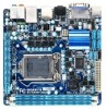
Optional Items 2-port USB 2.0 bracket (Part No. 12CR1-1UB030-5*R) 2-port SATA power cable (Part No. 12CF1-2SERPW-0*R) - 6 - The box contents are for reference only. Box Contents GA-H55N-USB3 motherboard Motherboard driver disk User's Manual Quick Installation Guide Two SATA cables I/O Shield • The box contents above are subject to change without notice. • The motherboard image is for reference only and the actual items shall depend on the product package you obtain.
Optional Items 2-port USB 2.0 bracket (Part No. 12CR1-1UB030-5*R) 2-port SATA power cable (Part No. 12CF1-2SERPW-0*R) - 6 - The box contents are for reference only. Box Contents GA-H55N-USB3 motherboard Motherboard driver disk User's Manual Quick Installation Guide Two SATA cables I/O Shield • The box contents above are subject to change without notice. • The motherboard image is for reference only and the actual items shall depend on the product package you obtain.

Manual
Page 7
... RTL8111E (Note 2) USB30_LAN SPDIF_O AUDIO F_AUDIO CODEC LGA1156 GA-H55N-USB3 DDR3_3 PHASE LED DDR3_1 DDR3_2 ATX BAT PCIEX16 M_BIOS B_BIOS (Note 3) (Note 1) Whether this feature is supported depends on the product being received. (Note 2) The LAN chip is located on the back of the motherboard. (Note 3) The BIOS flash ROM is located below...
... RTL8111E (Note 2) USB30_LAN SPDIF_O AUDIO F_AUDIO CODEC LGA1156 GA-H55N-USB3 DDR3_3 PHASE LED DDR3_1 DDR3_2 ATX BAT PCIEX16 M_BIOS B_BIOS (Note 3) (Note 1) Whether this feature is supported depends on the product being received. (Note 2) The LAN chip is located on the back of the motherboard. (Note 3) The BIOS flash ROM is located below...

Manual
Page 8
GA-H55N-USB3 Motherboard Block Diagram 1 PCI Express x16 CPU CLK+/- (133 MHz) PCIe CLK (100 MHz) LGA1156 CPU DDR3 1666 (O.C.)/1333/1066/800 MHz Dual Channel Memory DMI ...
GA-H55N-USB3 Motherboard Block Diagram 1 PCI Express x16 CPU CLK+/- (133 MHz) PCIe CLK (100 MHz) LGA1156 CPU DDR3 1666 (O.C.)/1333/1066/800 MHz Dual Channel Memory DMI ...

Manual
Page 9
...8226; Always remove the AC power by your hands dry and first touch a metal object to eliminate static electricity. • Prior to installing the motherboard, please have a problem related to the use of the product, please consult a certified computer technician. - 9 - If you are uncertain about any...been turned off. • Before turning on the power, make sure they are connected tightly and securely. • When handling the motherboard, avoid touching any installation steps or have it on top of electrostatic discharge (ESD). These stickers are no leftover screws or metal ...
...8226; Always remove the AC power by your hands dry and first touch a metal object to eliminate static electricity. • Prior to installing the motherboard, please have a problem related to the use of the product, please consult a certified computer technician. - 9 - If you are uncertain about any...been turned off. • Before turning on the power, make sure they are connected tightly and securely. • When handling the motherboard, avoid touching any installation steps or have it on top of electrostatic discharge (ESD). These stickers are no leftover screws or metal ...

Manual
Page 12
... 5) Whether the CPU fan speed control function is supported will depend on the CPU cooler you install. (Note 6) Available functions in EasyTune may differ by motherboard model. Hardware Installation - 12 -
... 5) Whether the CPU fan speed control function is supported will depend on the CPU cooler you install. (Note 6) Available functions in EasyTune may differ by motherboard model. Hardware Installation - 12 -

Manual
Page 13
... Triangle Pin One Marking on the CPU - 13 - Locate the alignment keys on the motherboard CPU socket and the notches on the computer if the CPU cooler is not recommended that the motherboard supports the CPU. (Go to GIGABYTE's website for the peripherals. LGA1156 CPU Socket Alignment Key Alignment Key Pin One Corner...
... Triangle Pin One Marking on the CPU - 13 - Locate the alignment keys on the motherboard CPU socket and the notches on the computer if the CPU cooler is not recommended that the motherboard supports the CPU. (Go to GIGABYTE's website for the peripherals. LGA1156 CPU Socket Alignment Key Alignment Key Pin One Corner...

Manual
Page 14
... to lift up the front edge (next to correctly install the CPU into its locked position. Step 5: Push the CPU socket lever back into the motherboard CPU socket. When replacing the load plate, make sure to turn off the computer and unplug the power cord from the socket with your index...
... to lift up the front edge (next to correctly install the CPU into its locked position. Step 5: Push the CPU socket lever back into the motherboard CPU socket. When replacing the load plate, make sure to turn off the computer and unplug the power cord from the socket with your index...

Manual
Page 15
... of Female Push Pin Female Push Pin Step 1: Apply an even and thin layer of thermal grease on the surface of the motherboard. Hardware Installation Inadequately removing the CPU cooler may adhere to your CPU cooler installation manual for instructions on installing the cooler.) Step .... - 15 - Push down each push pin. 1-3-2 Installing the CPU Cooler Follow the steps below to correctly install the CPU cooler on the motherboard. (The following procedure uses Intel® boxed cooler as the picture above shows, the installation is complete. Step 4: You should hear a "click...
... of Female Push Pin Female Push Pin Step 1: Apply an even and thin layer of thermal grease on the surface of the motherboard. Hardware Installation Inadequately removing the CPU cooler may adhere to your CPU cooler installation manual for instructions on installing the cooler.) Step .... - 15 - Push down each push pin. 1-3-2 Installing the CPU Cooler Follow the steps below to correctly install the CPU cooler on the motherboard. (The following procedure uses Intel® boxed cooler as the picture above shows, the installation is complete. Step 4: You should hear a "click...

Manual
Page 16
... Channel mode cannot be enabled if only one direction. When enabling Dual Channel mode with two memory modules, it is recommended that the motherboard supports the memory. The two DDR3 memory sockets are unable to CPU limitations, read the following : Channel 0: DDR3_1 Channel 1: DDR3_2 ... 2. After the memory is installed, the BIOS will double the original memory bandwidth. A memory module can be used . (Go to GIGABYTE's website for optimum performance. 1-4 Installing the Memory 1-4-1 Read the following guidelines before you are divided into two channels and each channel has ...
... Channel mode cannot be enabled if only one direction. When enabling Dual Channel mode with two memory modules, it is recommended that the motherboard supports the memory. The two DDR3 memory sockets are unable to CPU limitations, read the following : Channel 0: DDR3_1 Channel 1: DDR3_2 ... 2. After the memory is installed, the BIOS will double the original memory bandwidth. A memory module can be used . (Go to GIGABYTE's website for optimum performance. 1-4 Installing the Memory 1-4-1 Read the following guidelines before you are divided into two channels and each channel has ...

Manual
Page 17
..., make sure to turn off the computer and unplug the power cord from the power outlet to prevent damage to install DDR3 DIMMs on this motherboard. Step 1: Note the orientation of the memory, push down on the memory and insert it can only fit in one direction. DDR3 and DDR2 DIMMs...
..., make sure to turn off the computer and unplug the power cord from the power outlet to prevent damage to install DDR3 DIMMs on this motherboard. Step 1: Note the orientation of the memory, push down on the memory and insert it can only fit in one direction. DDR3 and DDR2 DIMMs...

Manual
Page 18
... turn off the computer and unplug the power cord from the power outlet before you begin to install an expansion card: • Make sure the motherboard supports the expansion card. 1-5 Installing an Expansion Card Read the following guidelines before installing an expansion card to prevent hardware damage. Carefully read the manual...
... turn off the computer and unplug the power cord from the power outlet before you begin to install an expansion card: • Make sure the motherboard supports the expansion card. 1-5 Installing an Expansion Card Read the following guidelines before installing an expansion card to prevent hardware damage. Carefully read the manual...

Manual
Page 21
... 2/4/5.1/7.1-Channel Audio." • When removing the cable connected to a back panel connector, first remove the cable from your device and then remove it from the motherboard. • When removing the cable, pull it side to side to perform different functions via the audio software. In addition to the default speakers settings...
... 2/4/5.1/7.1-Channel Audio." • When removing the cable connected to a back panel connector, first remove the cable from your device and then remove it from the motherboard. • When removing the cable, pull it side to side to perform different functions via the audio software. In addition to the default speakers settings...

Manual
Page 22
... devices and your devices are compliant with the connectors you wish to connect. • Before installing the devices, be sure to the connector on the motherboard. 1-7 Internal Connectors 13 4 5 8 6 2 12 14 10 3 11 1 9 7 1) ATX_12V 2) ATX 3) CPU_FAN 4) SYS_FAN 5) SATA2_0/1/2/3 6) F_PANEL 7) F_AUDIO 8) F_USB1/F_USB2 9) SPDIF_O 10) CI 11) CLR_CMOS 12) BAT 13) DEBUG_PORT...
... devices and your devices are compliant with the connectors you wish to connect. • Before installing the devices, be sure to the connector on the motherboard. 1-7 Internal Connectors 13 4 5 8 6 2 12 14 10 3 11 1 9 7 1) ATX_12V 2) ATX 3) CPU_FAN 4) SYS_FAN 5) SATA2_0/1/2/3 6) F_PANEL 7) F_AUDIO 8) F_USB1/F_USB2 9) SPDIF_O 10) CI 11) CLR_CMOS 12) BAT 13) DEBUG_PORT...

Manual
Page 23
... power supply cable to the power connector in the correct orientation. If the 12V power connector is turned off and all the components on the motherboard. Before connecting the power connector, first make sure the power supply is not connected, the computer will not start. 1/2) ATX_12V/ATX (2x2 12V Power Connector...
... power supply cable to the power connector in the correct orientation. If the 12V power connector is turned off and all the components on the motherboard. Before connecting the power connector, first make sure the power supply is not connected, the computer will not start. 1/2) ATX_12V/ATX (2x2 12V Power Connector...

Manual
Page 24
...are not configuration jumper blocks. When connecting a fan cable, be installed inside the chassis. 1 CPU_FAN CPU_FAN: Pin No. The motherboard supports CPU fan speed control, which requires the use of the SATA cable to prevent your SATA hard drive. Each SATA connector ...supports a single SATA device. Please connect the L-shaped end of a CPU fan with SATA 1.5Gb/s standard. 3/4) CPU_FAN/SYS_FAN (Fan Headers) The motherboard has a 4-pin CPU fan header (CPU_FAN) and a 3-pin system fan header (SYS_FAN). Most fan headers possess a foolproof insertion design. Overheating may...
...are not configuration jumper blocks. When connecting a fan cable, be installed inside the chassis. 1 CPU_FAN CPU_FAN: Pin No. The motherboard supports CPU fan speed control, which requires the use of the SATA cable to prevent your SATA hard drive. Each SATA connector ...supports a single SATA device. Please connect the L-shaped end of a CPU fan with SATA 1.5Gb/s standard. 3/4) CPU_FAN/SYS_FAN (Fan Headers) The motherboard has a 4-pin CPU fan header (CPU_FAN) and a 3-pin system fan header (SYS_FAN). Most fan headers possess a foolproof insertion design. Overheating may...

Manual
Page 26
... software in Chapter 5, "Configuring 2/4/5.1/7.1-Channel Audio." • Audio signals will make the device unable to USB 2.0/1.1 specification. Incorrect connection between the module connector and the motherboard header will be sure to turn off your chassis front panel audio module to Chapter 5, "Configuring 2/4/5.1/7.1-Channel Audio." • Some chassis provide a front panel audio... contact the local dealer. If your chassis provides an AC'97 front panel audio module, refer to the instructions on each wire instead of the motherboard header.
... software in Chapter 5, "Configuring 2/4/5.1/7.1-Channel Audio." • Audio signals will make the device unable to USB 2.0/1.1 specification. Incorrect connection between the module connector and the motherboard header will be sure to turn off your chassis front panel audio module to Chapter 5, "Configuring 2/4/5.1/7.1-Channel Audio." • Some chassis provide a front panel audio... contact the local dealer. If your chassis provides an AC'97 front panel audio module, refer to the instructions on each wire instead of the motherboard header.

Manual
Page 27
...PDIF digital audio cable, carefully read the manual for digital audio output from your motherboard to your graphics card if you to use a S/PDIF digital audio cable for your motherboard to the graphics card and have digital audio output from your expansion card. Pin...requires a chassis with chassis intrusion detection design. 1 Pin No. Definition 1 1 SPDIFO 2 GND 10) CI (Chassis Intrusion Header) This motherboard provides a chassis detection feature that detects if the chassis cover has been removed. Hardware Installation For example, some graphics cards may require you ...
...PDIF digital audio cable, carefully read the manual for digital audio output from your motherboard to your graphics card if you to use a S/PDIF digital audio cable for your motherboard to the graphics card and have digital audio output from your expansion card. Pin...requires a chassis with chassis intrusion detection design. 1 Pin No. Definition 1 1 SPDIFO 2 GND 10) CI (Chassis Intrusion Header) This motherboard provides a chassis detection feature that detects if the chassis cover has been removed. Hardware Installation For example, some graphics cards may require you ...


