Manual
Page 4
... ...6 GA-G33M-S2H Motherboard Layout 7 Block Diagram ...8 Chapter 1 Hardware Installation 9 1-1 Installation Precautions 9 1-2 Product Specifications 10 1-3 Installing the CPU and CPU Cooler 13 1-3-1 Installing the CPU 13 1-3-2 Installing the CPU Cooler 15 1-4 Installing the Memory 16 1-4-1 Dual Channel Memory Configuration 16 1-4-2 Installing a Memory 17 1-5 Installing an Expansion Card 18 1-6 Back Panel Connectors 21 1-7 Internal Connectors 24 Chapter 2 BIOS Setup 35 2-1 Startup Screen 36 2-2 The Main Menu 37 2-3 Standard CMOS Features 39 2-4 Advanced BIOS Features...
... ...6 GA-G33M-S2H Motherboard Layout 7 Block Diagram ...8 Chapter 1 Hardware Installation 9 1-1 Installation Precautions 9 1-2 Product Specifications 10 1-3 Installing the CPU and CPU Cooler 13 1-3-1 Installing the CPU 13 1-3-2 Installing the CPU Cooler 15 1-4 Installing the Memory 16 1-4-1 Dual Channel Memory Configuration 16 1-4-2 Installing a Memory 17 1-5 Installing an Expansion Card 18 1-6 Back Panel Connectors 21 1-7 Internal Connectors 24 Chapter 2 BIOS Setup 35 2-1 Startup Screen 36 2-2 The Main Menu 37 2-3 Standard CMOS Features 39 2-4 Advanced BIOS Features...
Manual
Page 10
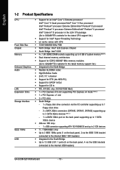
...1 x PCI Express x16 slot supporting PCI Express x4 mode (Note 2) Š 1 x PCI Express x1 slot Š 2 x PCI slots Š South Bridge: - 1 x floppy disk drive connector via the USB brackets connected to 2 IDE devices Š T.I /O controller supporting up to 1 floppy disk drive - 3 x SATA 3Gb/s connectors (SATAII0, SATAII1, SATAII2) supporting up to 3 SATA 3Gb/s devices (Note 3) - 1 x eSATA 3Gb/s port on the back panel supporting up to 1 SATA 3Gb/s device Š JMicron 368 chip: - 1 x IDE connector supporting ATA-133/100/66/33 and up to the internal USB headers) GA-G33M-S2H Motherboard...
...1 x PCI Express x16 slot supporting PCI Express x4 mode (Note 2) Š 1 x PCI Express x1 slot Š 2 x PCI slots Š South Bridge: - 1 x floppy disk drive connector via the USB brackets connected to 2 IDE devices Š T.I /O controller supporting up to 1 floppy disk drive - 3 x SATA 3Gb/s connectors (SATAII0, SATAII1, SATAII2) supporting up to 3 SATA 3Gb/s devices (Note 3) - 1 x eSATA 3Gb/s port on the back panel supporting up to 1 SATA 3Gb/s device Š JMicron 368 chip: - 1 x IDE connector supporting ATA-133/100/66/33 and up to the internal USB headers) GA-G33M-S2H Motherboard...
Manual
Page 12
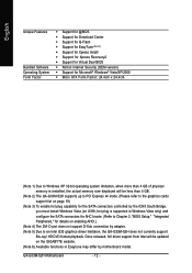
... to Windows XP 32-bit operating system limitation, when more than 4 GB. (Note 2) The GA-G33M-S2H supports up to PCI Express x4 mode. (Please refer to the graphics cards support list on page 19) (Note 3) To enable hot plug capability for the SATA connectors controlled by the ICH9 South Bridge, you must install Windows Vista (on ICH9, hot plug is supported in Windows Vista only) and configure the SATA connectors for AHCI mode. (Refer to Chapter 2, "BIOS Setup," "Integrated...
... to Windows XP 32-bit operating system limitation, when more than 4 GB. (Note 2) The GA-G33M-S2H supports up to PCI Express x4 mode. (Please refer to the graphics cards support list on page 19) (Note 3) To enable hot plug capability for the SATA connectors controlled by the ICH9 South Bridge, you must install Windows Vista (on ICH9, hot plug is supported in Windows Vista only) and configure the SATA connectors for AHCI mode. (Refer to Chapter 2, "BIOS Setup," "Integrated...
Manual
Page 16
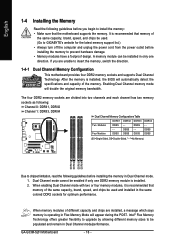
... GIGABYTE's website for optimum performance. Dual Channel mode cannot be used . (Go to insert the memory, switch the direction. 1-4-1 Dual Channel Memory Configuration This motherboard provides four DDR2 memory sockets and supports Dual Channel Technology. DS/SS - - Four Modules DS/SS DS/SS DS/SS DDRII4 - When memory modules of the memory. DS/SS - - It is operating in only one DDR2 memory module is installed, the BIOS will double the original memory bandwidth. When enabling Dual Channel mode...
... GIGABYTE's website for optimum performance. Dual Channel mode cannot be used . (Go to insert the memory, switch the direction. 1-4-1 Dual Channel Memory Configuration This motherboard provides four DDR2 memory sockets and supports Dual Channel Technology. DS/SS - - Four Modules DS/SS DS/SS DS/SS DDRII4 - When memory modules of the memory. DS/SS - - It is operating in only one DDR2 memory module is installed, the BIOS will double the original memory bandwidth. When enabling Dual Channel mode...
Manual
Page 18
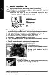
... slot. Install the driver provided with a screw. 5. Align the card with your card. After installing all expansion cards, replace the chassis cover(s). 6. Example: Installing and Removing a PCI Express x16 Graphics Card: • Installing a Graphics Card: Gently insert the graphics card into the slot. 4. If necessary, go to BIOS Setup to install an expansion card: • Make sure the motherboard supports the expansion card. Make sure the graphics card is fully seated in the expansion slot. 1. GA-G33M-S2H Motherboard - 18 - Carefully read the manual that supports...
... slot. Install the driver provided with a screw. 5. Align the card with your card. After installing all expansion cards, replace the chassis cover(s). 6. Example: Installing and Removing a PCI Express x16 Graphics Card: • Installing a Graphics Card: Gently insert the graphics card into the slot. 4. If necessary, go to BIOS Setup to install an expansion card: • Make sure the motherboard supports the expansion card. Make sure the graphics card is fully seated in the expansion slot. 1. GA-G33M-S2H Motherboard - 18 - Carefully read the manual that supports...
Manual
Page 21
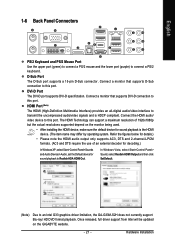
... graphics driver limitation, the GA-G33M-S2H does not currently support Blu-ray/ HD DVD format playback. DVI-D Port The DVI-D port supports DVI-D specifictation. Once released, full driver support from Intel will be updated on the monitor being used. • After installing the HDMI device, make sure the default device for sound playback to this port. The HDMI Technology can support a maximum resolution of an external decoder for decoding.) In Windows XP, select Start>Control Panel>Sounds and Audio Devices>Audio, set the Default device...
... graphics driver limitation, the GA-G33M-S2H does not currently support Blu-ray/ HD DVD format playback. DVI-D Port The DVI-D port supports DVI-D specifictation. Once released, full driver support from Intel will be updated on the monitor being used. • After installing the HDMI device, make sure the default device for sound playback to this port. The HDMI Technology can support a maximum resolution of an external decoder for decoding.) In Windows XP, select Start>Control Panel>Sounds and Audio Devices>Audio, set the Default device...
Manual
Page 22
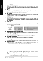
... Port The IEEE 1394 port supports the IEEE 1394a specification, featuring high speed, high bandwidth and hotplug capabilities. Use this port for line in devices such as an USB keyboard/mouse, USB printer, USB flash drive and etc. English Optical S/PDIF Out Connector This connector provides digital audio out to connect center/subwoofer speakers in a 5.1/7.1-channel audio configuration. Use this audio jack to an external audio system that your device and then remove it from the motherboard. • When removing the cable...
... Port The IEEE 1394 port supports the IEEE 1394a specification, featuring high speed, high bandwidth and hotplug capabilities. Use this port for line in devices such as an USB keyboard/mouse, USB printer, USB flash drive and etc. English Optical S/PDIF Out Connector This connector provides digital audio out to connect center/subwoofer speakers in a 5.1/7.1-channel audio configuration. Use this audio jack to an external audio system that your device and then remove it from the motherboard. • When removing the cable...
Manual
Page 26
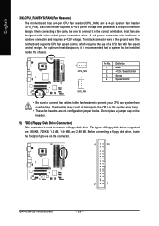
... +12V voltage. The types of a CPU fan with color-coded power connector wires. Do not place a jumper cap on the connector. 34 33 2 1 GA-G33M-S2H Motherboard - 26 - Before connecting a floppy disk drive, locate the foolproof groove on the headers. 5) FDD (Floppy Disk Drive Connector) This connector is used to prevent your CPU and system from overheating. When connecting a fan cable, be installed inside the chassis. 1 CPU_FAN 1 Pin No. 1 2 3 4 Definition GND +12V / Speed Control Sense Speed Control SYS_FAN • Be sure to connect fan cables to the fan headers to connect...
... +12V voltage. The types of a CPU fan with color-coded power connector wires. Do not place a jumper cap on the connector. 34 33 2 1 GA-G33M-S2H Motherboard - 26 - Before connecting a floppy disk drive, locate the foolproof groove on the headers. 5) FDD (Floppy Disk Drive Connector) This connector is used to prevent your CPU and system from overheating. When connecting a fan cable, be installed inside the chassis. 1 CPU_FAN 1 Pin No. 1 2 3 4 Definition GND +12V / Speed Control Sense Speed Control SYS_FAN • Be sure to connect fan cables to the fan headers to connect...
Manual
Page 38
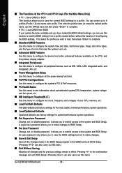
... the BIOS Setup program to the CMOS and exit BIOS Setup. (Pressing can use this menu to configure the clock, frequency and voltages of errors that stop the system boot, etc. „ Advanced BIOS Features Use this menu to configure the device boot order, advanced features available on the CPU, and the primary display adapter. „ Integrated Peripherals Use this menu to configure all peripheral devices, such as IDE, SATA, USB, integrated audio, and integrated LAN, etc. „ Power Management Setup Use this...
... the BIOS Setup program to the CMOS and exit BIOS Setup. (Pressing can use this menu to configure the clock, frequency and voltages of errors that stop the system boot, etc. „ Advanced BIOS Features Use this menu to configure the device boot order, advanced features available on the CPU, and the primary display adapter. „ Integrated Peripherals Use this menu to configure all peripheral devices, such as IDE, SATA, USB, integrated audio, and integrated LAN, etc. „ Power Management Setup Use this...

Manual
Page 39
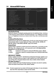
... Channel 2, 3 Master, IDE Channel 4 Master/Slave IDE Auto-Detection Press to None so the system will • Manual Access Mode skip the detection of the IDE/SATA device on this channel. Access Mode Sets the hard drive access mode. Options are : Auto (default), Large. - 39 - Options are : Auto (default), CHS, LBA, Large. BIOS Setup Extended IDE Drive Configure your IDE/SATA devices by using one of the three methods below : • Auto Lets BIOS automatically detect IDE/SATA devices during the POST. (Default) • None If no IDE/SATA devices are used , set...
... Channel 2, 3 Master, IDE Channel 4 Master/Slave IDE Auto-Detection Press to None so the system will • Manual Access Mode skip the detection of the IDE/SATA device on this channel. Access Mode Sets the hard drive access mode. Options are : Auto (default), Large. - 39 - Options are : Auto (default), CHS, LBA, Large. BIOS Setup Extended IDE Drive Configure your IDE/SATA devices by using one of the three methods below : • Auto Lets BIOS automatically detect IDE/SATA devices during the POST. (Default) • None If no IDE/SATA devices are used , set...
Manual
Page 41
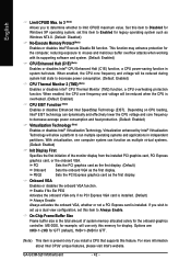
...the BIOS Setup program. (Default) System A password is required for booting the system and for operating systems that supports this feature. Capability CPU Hyper-Threading (Note) Limit CPUID Max. Press to accept. to 3 (Note) No-Execute Memory Protect (Note) CPU Enhanced Halt (C1E) (Note) CPU Thermal Monitor 2(TM2) (Note) CPU EIST Function (Note) Virtualization Technology (Note) Init Display First Onboard VGA On-Chip Frame Buffer Size [Press Enter] [Floppy] [Hard Disk] [CDROM] [Setup] [Disabled] [Enabled] [Disabled] [Enabled] [Enabled] [Enabled] [Enabled] [Enabled] [PCI] [Enable If...
...the BIOS Setup program. (Default) System A password is required for booting the system and for operating systems that supports this feature. Capability CPU Hyper-Threading (Note) Limit CPUID Max. Press to accept. to 3 (Note) No-Execute Memory Protect (Note) CPU Enhanced Halt (C1E) (Note) CPU Thermal Monitor 2(TM2) (Note) CPU EIST Function (Note) Virtualization Technology (Note) Init Display First Onboard VGA On-Chip Frame Buffer Size [Press Enter] [Floppy] [Hard Disk] [CDROM] [Setup] [Disabled] [Enabled] [Disabled] [Enabled] [Enabled] [Enabled] [Enabled] [Enabled] [PCI] [Enable If...
Manual
Page 42
... installed PCI graphics card, PCI Express graphics card, or the onboard VGA. GA-G33M-S2H Motherboard - 42 - When enabled, the CPU core frequency and voltage will be reduced when the CPU is installed. Virtualization enhanced by Intel® Virtualization Technology will use only this item to decrease average power consumption and heat production. (Default: Enabled) Virtualization Technology (Note) Enables or disables Intel® Virtualization Technology. If you to determine whether to run multiple operating systems and applications in system halt state. PCI Sets the PCI...
... installed PCI graphics card, PCI Express graphics card, or the onboard VGA. GA-G33M-S2H Motherboard - 42 - When enabled, the CPU core frequency and voltage will be reduced when the CPU is installed. Virtualization enhanced by Intel® Virtualization Technology will use only this item to decrease average power consumption and heat production. (Default: Enabled) Virtualization Technology (Note) Enables or disables Intel® Virtualization Technology. If you to determine whether to run multiple operating systems and applications in system halt state. PCI Sets the PCI...
Manual
Page 43
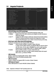
... support Native mode, e.g. Windows XP/2000. Set this option to Disabled if you wish to install operating Enabled systems that support Native mode, e.g. English 2-5 Integrated Peripherals CMOS Setup Utility-Copyright (C) 1984-2007 Award Software Integrated Peripherals SATA AHCI Mode SATA Port0-1 Native Mode USB Controller USB 2.0 Controller USB Keyboard Support USB Mouse Support Legacy USB storage detect Azalia Codec Onboard H/W 1394 Onboard H/W LAN ` SMART LAN Onboard LAN Boot ROM Onboard IDE Controller Onboard Serial Port 1 Onboard Parallel Port Parallel Port Mode [Disabled...
... support Native mode, e.g. Windows XP/2000. Set this option to Disabled if you wish to install operating Enabled systems that support Native mode, e.g. English 2-5 Integrated Peripherals CMOS Setup Utility-Copyright (C) 1984-2007 Award Software Integrated Peripherals SATA AHCI Mode SATA Port0-1 Native Mode USB Controller USB 2.0 Controller USB Keyboard Support USB Mouse Support Legacy USB storage detect Azalia Codec Onboard H/W 1394 Onboard H/W LAN ` SMART LAN Onboard LAN Boot ROM Onboard IDE Controller Onboard Serial Port 1 Onboard Parallel Port Parallel Port Mode [Disabled...
Manual
Page 44
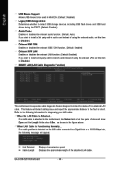
... network card instead of wires will detect cabling issue and report the approximate distance to the fault or short. Onboard H/W 1394 Enables or disables the onboard IEEE 1394 function. (Default: Enabled) Onboard H/W LAN Enables or disables the onboard LAN function. (Default: Enabled) If you wish to install a 3rd party add-in audio card instead of using the onboard LAN, set this item to Disabled. SMART LAN (LAN Cable Diagnostic Function) CMOS Setup Utility-Copyright (C) 1984-2007 Award Software SMART LAN Start detecting at Port..... Refer to Disabled. Link Detected --> 100Mbps Cable...
... network card instead of wires will detect cabling issue and report the approximate distance to the fault or short. Onboard H/W 1394 Enables or disables the onboard IEEE 1394 function. (Default: Enabled) Onboard H/W LAN Enables or disables the onboard LAN function. (Default: Enabled) If you wish to install a 3rd party add-in audio card instead of using the onboard LAN, set this item to Disabled. SMART LAN (LAN Cable Diagnostic Function) CMOS Setup Utility-Copyright (C) 1984-2007 Award Software SMART LAN Start detecting at Port..... Refer to Disabled. Link Detected --> 100Mbps Cable...
Manual
Page 45
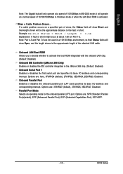
... Capabilities Port), ECP+EPP. - 45 - Options are : Auto, 3F8/IRQ4 (default), 2F8/IRQ3, 3E8/IRQ4, 2E8/IRQ3, Disabled. Options are not used in a 10/100 Mbps environment, so their Status fields will show Short and thenlength shown will be the approximate distance to activate the boot ROM integrated with the onboard LAN chip. (Default: Disabled) Onboard IDE Controller (JMicron 368 Chip) Enables or disables the IDE controller integrated in Windows mode or when the LAN Boot ROM is...
... Capabilities Port), ECP+EPP. - 45 - Options are : Auto, 3F8/IRQ4 (default), 2F8/IRQ3, 3E8/IRQ4, 2E8/IRQ3, Disabled. Options are not used in a 10/100 Mbps environment, so their Status fields will show Short and thenlength shown will be the approximate distance to activate the boot ROM integrated with the onboard LAN chip. (Default: Disabled) Onboard IDE Controller (JMicron 368 Chip) Enables or disables the IDE controller integrated in Windows mode or when the LAN Boot ROM is...

Manual
Page 50
... is populated. However, for a 4-pin CPU fan. A small portion of system memory will be controlled by the Intel Quiet System Technology (QST). GA-G33M-S2H Motherboard - 50 - Auto Lets BIOS autodetect the type of Intel Host Embedded Control Interface (HECI) driver from the motherboard driver disk. Auto Lets BIOS control CPU fan speed. (Default) Intel(R) QST Allows CPU fan speed to Intel(R) QST, make sure at least DDRII1 or DDRII2 socket in Channel 0 is enabled. English Smart FAN Control Method (Note) Specifies how to control CPU fan speed.
... is populated. However, for a 4-pin CPU fan. A small portion of system memory will be controlled by the Intel Quiet System Technology (QST). GA-G33M-S2H Motherboard - 50 - Auto Lets BIOS autodetect the type of Intel Host Embedded Control Interface (HECI) driver from the motherboard driver disk. Auto Lets BIOS control CPU fan speed. (Default) Intel(R) QST Allows CPU fan speed to Intel(R) QST, make sure at least DDRII1 or DDRII2 socket in Channel 0 is enabled. English Smart FAN Control Method (Note) Specifies how to control CPU fan speed.

Manual
Page 51
... for advanced users only and we recommend you set the R.G.B. Options are: Auto (default), Fast, Turbo. BIOS Setup If this feature. - 51 - Enabled will allow for the installed CPU. English 2-9 MB Intelligent Tweaker(M.I.T.) CMOS Setup Utility-Copyright (C) 1984-2007 Award Software MB Intelligent Tweaker(M.I.T.) Robust Graphics Booster CPU Clock Ratio (Note) CPU Host Clock Control x CPU Host Frequency (Mhz) PCI Express Frequency (Mhz) System Memory Multiplier (SPD) Memory Frequency (Mhz) 667 High Speed DRAM DLL Settings Performance Enhance ******** System Voltage Optimized System...
... for advanced users only and we recommend you set the R.G.B. Options are: Auto (default), Fast, Turbo. BIOS Setup If this feature. - 51 - Enabled will allow for the installed CPU. English 2-9 MB Intelligent Tweaker(M.I.T.) CMOS Setup Utility-Copyright (C) 1984-2007 Award Software MB Intelligent Tweaker(M.I.T.) Robust Graphics Booster CPU Clock Ratio (Note) CPU Host Clock Control x CPU Host Frequency (Mhz) PCI Express Frequency (Mhz) System Memory Multiplier (SPD) Memory Frequency (Mhz) 667 High Speed DRAM DLL Settings Performance Enhance ******** System Voltage Optimized System...
Manual
Page 56
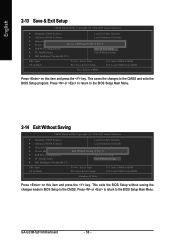
This exits the BIOS Setup without saving the changes made in BIOS Setup to the BIOS Setup Main Menu. GA-G33M-S2H Motherboard - 56 - Press or to return to the BIOS Setup Main Menu. 2-14 Exit Without Saving CMOS Setup Utility-Copyright (C) 1984-2007 Award Software ` Standard CMOS Features Load Fail-Safe Defaults ` Advanced BIOS Features Load Optimized Defaults ` Integrated Peripherals Set Supervisor Password ` Power Management Setup Quit Without Saving (SYe/tNU)?seNr Password ` PnP/PCI Configurations Save & Exit Setup ` PC Health Status Exit Without Saving ` MB ...
This exits the BIOS Setup without saving the changes made in BIOS Setup to the BIOS Setup Main Menu. GA-G33M-S2H Motherboard - 56 - Press or to return to the BIOS Setup Main Menu. 2-14 Exit Without Saving CMOS Setup Utility-Copyright (C) 1984-2007 Award Software ` Standard CMOS Features Load Fail-Safe Defaults ` Advanced BIOS Features Load Optimized Defaults ` Integrated Peripherals Set Supervisor Password ` Power Management Setup Quit Without Saving (SYe/tNU)?seNr Password ` PnP/PCI Configurations Save & Exit Setup ` PC Health Status Exit Without Saving ` MB ...
Manual
Page 79
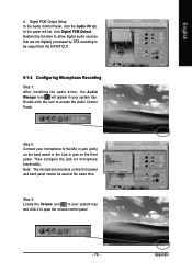
... Step 1: After installing the audio driver, the Audio Manager icon will appear in your microphone to access the Audio Control Panel. Note: The microphone functions on the front panel. Step 2: Connect your system tray and click it to be used at the same time. Then configure the jack for microphone functionality. Step 3: Locate the Volume icon in your system tray. Enable this function to...
... Step 1: After installing the audio driver, the Audio Manager icon will appear in your microphone to access the Audio Control Panel. Note: The microphone functions on the front panel. Step 2: Connect your system tray and click it to be used at the same time. Then configure the jack for microphone functionality. Step 3: Locate the Volume icon in your system tray. Enable this function to...

Manual
Page 82
... possible computer problems. (For reference only.) 1 short: System boots successfully 2 short: CMOS setting error 1 long, 1 short: Memory or motherboard error 1 long, 2 short: Monitor or graphics card error 1 long, 3 short: Keyboard error 1 long, 9 short: BIOS ROM error Continuous long beeps: Graphics card not inserted properly Continuous short beeps: Power error GA-G33M-S2H Motherboard - 82 - If your computer. If not, try a speaker with an internal amplifier. In the Main Menu, press + to enter BIOS Setup. Turn off your motherboard, please go to the instructions on the...
... possible computer problems. (For reference only.) 1 short: System boots successfully 2 short: CMOS setting error 1 long, 1 short: Memory or motherboard error 1 long, 2 short: Monitor or graphics card error 1 long, 3 short: Keyboard error 1 long, 9 short: BIOS ROM error Continuous long beeps: Graphics card not inserted properly Continuous short beeps: Power error GA-G33M-S2H Motherboard - 82 - If your computer. If not, try a speaker with an internal amplifier. In the Main Menu, press + to enter BIOS Setup. Turn off your motherboard, please go to the instructions on the...


