Manual
Page 1
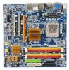
GA-G33M-S2H LGA775 socket motherboard for Intel® CoreTM processor family/ Intel® Pentium® processor family/Intel® Celeron® processor family User's Manual Rev. 1001 12ME-G33MS2H-1001R * The WEEE marking on the product indicates this product must not be disposed of with user's other household waste and must be handed over to a designated collection point for the recycling of waste electrical and electronic equipment!! * The WEEE marking applies only in European Union's member states.
GA-G33M-S2H LGA775 socket motherboard for Intel® CoreTM processor family/ Intel® Pentium® processor family/Intel® Celeron® processor family User's Manual Rev. 1001 12ME-G33MS2H-1001R * The WEEE marking on the product indicates this product must not be disposed of with user's other household waste and must be handed over to a designated collection point for the recycling of waste electrical and electronic equipment!! * The WEEE marking applies only in European Union's member states.
Manual
Page 2
Motherboard GA-G33M-S2H Jul. 13, 2007 Motherboard GA-G33M-S2H Jul. 13, 2007
Motherboard GA-G33M-S2H Jul. 13, 2007 Motherboard GA-G33M-S2H Jul. 13, 2007

Manual
Page 3
...any form or by copyright laws and is the property of the motherboard is 1.0. For product-related information, check on our website at: http://www.gigabyte.com.tw Identifying Your Motherboard Revision The revision number on our website. is exclusively licensed to ...published in this manual are legally registered to GIGABYTE UNITED INC. Changes to the specifications and features in any means without prior notice. Check your motherboard looks like this product, GIGABYTE provides the following types of GIGABYTE branded motherboards. The logo is designated by GIGA-BYTE ...
...any form or by copyright laws and is the property of the motherboard is 1.0. For product-related information, check on our website at: http://www.gigabyte.com.tw Identifying Your Motherboard Revision The revision number on our website. is exclusively licensed to ...published in this manual are legally registered to GIGABYTE UNITED INC. Changes to the specifications and features in any means without prior notice. Check your motherboard looks like this product, GIGABYTE provides the following types of GIGABYTE branded motherboards. The logo is designated by GIGA-BYTE ...
Manual
Page 4
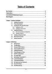
Table of Contents Box Contents ...6 OptionalItems ...6 GA-G33M-S2H Motherboard Layout 7 Block Diagram ...8 Chapter 1 Hardware Installation 9 1-1 Installation Precautions 9 1-2 Product Specifications 10 1-3 Installing the CPU and CPU Cooler 13 1-3-1 Installing the CPU 13 1-3-2 Installing the CPU ...
Table of Contents Box Contents ...6 OptionalItems ...6 GA-G33M-S2H Motherboard Layout 7 Block Diagram ...8 Chapter 1 Hardware Installation 9 1-1 Installation Precautions 9 1-2 Product Specifications 10 1-3 Installing the CPU and CPU Cooler 13 1-3-1 Installing the CPU 13 1-3-2 Installing the CPU ...
Manual
Page 6
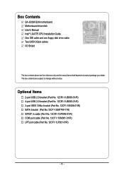
... (Part No. 12CF1-1LP001-01R) - 6 - The box contents are for reference only and the actual items shall depend on product package you obtain. Box Contents GA-G33M-S2H motherboard Motherboard driver disk User's Manual Intel® LGA775 CPU Installation Guide One IDE cable and one floppy disk drive cable Two SATA 3Gb/s cables I/O Shield The...
... (Part No. 12CF1-1LP001-01R) - 6 - The box contents are for reference only and the actual items shall depend on product package you obtain. Box Contents GA-G33M-S2H motherboard Motherboard driver disk User's Manual Intel® LGA775 CPU Installation Guide One IDE cable and one floppy disk drive cable Two SATA 3Gb/s cables I/O Shield The...
Manual
Page 9
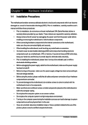
...• Always remove the AC power by your dealer. Hardware Installation English Chapter 1 Hardware Installation 1-1 Installation Precautions The motherboard contains numerous delicate electronic circuits and components which can lead to damage to system components as well as physical harm to the... a electrostatic shielding container. • Before unplugging the power supply cable from the power outlet before installing or removing the motherboard or other hardware components. • When connecting hardware components to wear an electrostatic discharge (ESD) wrist strap when handling ...
...• Always remove the AC power by your dealer. Hardware Installation English Chapter 1 Hardware Installation 1-1 Installation Precautions The motherboard contains numerous delicate electronic circuits and components which can lead to damage to system components as well as physical harm to the... a electrostatic shielding container. • Before unplugging the power supply cable from the power outlet before installing or removing the motherboard or other hardware components. • When connecting hardware components to wear an electrostatic discharge (ESD) wrist strap when handling ...
Manual
Page 10
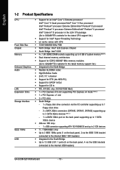
...of system memory (Note 1) Š Dual channel memory architecture Š Support for DDR2 800/667 MHz memory modules (Go to GIGABYTE's website for CD In Š RTL 8110SC chip (10/100/1000 Mbit) Š 1 x PCI Express x16 slot supporting...Edition/Intel® Pentium® 4 processor/ Intel® Celeron® D processor in the LGA 775 package (Go to GIGABYTE's website for the latest CPU support list.) Š Support for Intel® Hyper-Threading Technology Š L2 cache varies ...138; 4 x 1.8V DDR2 DIMM sockets supporting up to the internal USB headers) GA-G33M-S2H Motherboard - 10 -
...of system memory (Note 1) Š Dual channel memory architecture Š Support for DDR2 800/667 MHz memory modules (Go to GIGABYTE's website for CD In Š RTL 8110SC chip (10/100/1000 Mbit) Š 1 x PCI Express x16 slot supporting...Edition/Intel® Pentium® 4 processor/ Intel® Celeron® D processor in the LGA 775 package (Go to GIGABYTE's website for the latest CPU support list.) Š Support for Intel® Hyper-Threading Technology Š L2 cache varies ...138; 4 x 1.8V DDR2 DIMM sockets supporting up to the internal USB headers) GA-G33M-S2H Motherboard - 10 -
Manual
Page 12
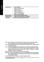
GA-G33M-S2H Motherboard - 12 - Once released, full driver support from Intel will be less than 4 GB. (Note 2) The GA-G33M-S2H supports up to PCI Express x4 mode. (Please refer to the graphics cards support list on page 19) (Note 3) To enable hot plug capability... Install Š Support for Xpress Recovery2 Š Support for Virtual Dual BIOS Š Norton Internet Security (OEM version) Š Support for details on the GIGABYTE website. (Note 6) Available functions in Easytune may differ by adapter. (Note 5) Due to Windows XP 32-bit operating system limitation, when more than 4 GB...
GA-G33M-S2H Motherboard - 12 - Once released, full driver support from Intel will be less than 4 GB. (Note 2) The GA-G33M-S2H supports up to PCI Express x4 mode. (Please refer to the graphics cards support list on page 19) (Note 3) To enable hot plug capability... Install Š Support for Xpress Recovery2 Š Support for Virtual Dual BIOS Š Norton Internet Security (OEM version) Š Support for details on the GIGABYTE website. (Note 6) Available functions in Easytune may differ by adapter. (Note 5) Due to Windows XP 32-bit operating system limitation, when more than 4 GB...

Manual
Page 13
...is not recom- Notch Triangle Pin One Marking on the CPU. It is optimized for the peripherals. Locate the alignment keys on the motherboard CPU socket and the notches on the CPU Hardware Installation LGA775 CPU Socket Alignment Key LGA 775 CPU Alignment Key Pin One Corner of... computer and unplug the power cord from the power outlet before you begin to install the CPU: • Make sure that the motherboard supports the CPU. (Go to GIGABYTE's website for instructions on enabling the HT Technology.) 1-3-1 Installing the CPU A. English 1-3 Installing the CPU and CPU Cooler Read the...
...is not recom- Notch Triangle Pin One Marking on the CPU. It is optimized for the peripherals. Locate the alignment keys on the motherboard CPU socket and the notches on the CPU Hardware Installation LGA775 CPU Socket Alignment Key LGA 775 CPU Alignment Key Pin One Corner of... computer and unplug the power cord from the power outlet before you begin to install the CPU: • Make sure that the motherboard supports the CPU. (Go to GIGABYTE's website for instructions on enabling the HT Technology.) 1-3-1 Installing the CPU A. English 1-3 Installing the CPU and CPU Cooler Read the...
Manual
Page 14
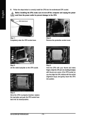
... sure to turn off the computer and unplug the power cord from the power outlet to prevent damage to correctly install the CPU into the motherboard CPU socket. GA-G33M-S2H Motherboard - 14 - English B. CPU Socket Lever Step 1: Completely raise the CPU socket lever.
... sure to turn off the computer and unplug the power cord from the power outlet to prevent damage to correctly install the CPU into the motherboard CPU socket. GA-G33M-S2H Motherboard - 14 - English B. CPU Socket Lever Step 1: Completely raise the CPU socket lever.

Manual
Page 15
...If the push pin is inserted as the example cooler.) Step 1: Apply an even and thin layer of thermal grease on the surface of the motherboard. Hardware Installation Use extreme care when removing the CPU cooler because the thermal grease/tape between the CPU cooler and CPU may damage the CPU.... the back of the installed CPU. English 1-3-2 Installing the CPU Cooler Follow the steps below to correctly install the CPU cooler on the motherboard. (The following procedure uses Intel® boxed cooler as the picture above, the installation is to the CPU fan header (CPU_FAN) on the...
...If the push pin is inserted as the example cooler.) Step 1: Apply an even and thin layer of thermal grease on the surface of the motherboard. Hardware Installation Use extreme care when removing the CPU cooler because the thermal grease/tape between the CPU cooler and CPU may damage the CPU.... the back of the installed CPU. English 1-3-2 Installing the CPU Cooler Follow the steps below to correctly install the CPU cooler on the motherboard. (The following procedure uses Intel® boxed cooler as the picture above, the installation is to the CPU fan header (CPU_FAN) on the...
Manual
Page 16
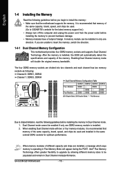
...GA-G33M-S2H Motherboard - 16 - A memory module can be populated and remain in Dual Channel mode/performance. When enabling Dual Channel mode with two or four memory modules, it is operating in Dual Channel mode. 1. If you begin to install the memory: • Make sure that the motherboard...unable to insert the memory, switch the direction. 1-4-1 Dual Channel Memory Configuration This motherboard provides four DDR2 memory sockets and supports Dual Channel Technology. The four DDR2 memory sockets...) DDRII1 DDRII2 DDRII3 DDRII4 Due to GIGABYTE's website for optimum performance.
...GA-G33M-S2H Motherboard - 16 - A memory module can be populated and remain in Dual Channel mode/performance. When enabling Dual Channel mode with two or four memory modules, it is operating in Dual Channel mode. 1. If you begin to install the memory: • Make sure that the motherboard...unable to insert the memory, switch the direction. 1-4-1 Dual Channel Memory Configuration This motherboard provides four DDR2 memory sockets and supports Dual Channel Technology. The four DDR2 memory sockets...) DDRII1 DDRII2 DDRII3 DDRII4 Due to GIGABYTE's website for optimum performance.
Manual
Page 17
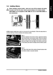
... of the socket will snap into the memory socket. Step 2: The clips at both ends of the memory module. Place the memory module on this motherboard. Spread the retaining clips at both ends of the memory, push down on the memory and insert it can only fit in one direction. Notch...
... of the socket will snap into the memory socket. Step 2: The clips at both ends of the memory module. Place the memory module on this motherboard. Spread the retaining clips at both ends of the memory, push down on the memory and insert it can only fit in one direction. Notch...
Manual
Page 18
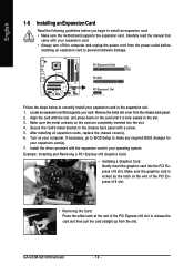
...Example: Installing and Removing a PCI Express x16 Graphics Card: • Installing a Graphics Card: Gently insert the graphics card into the slot. 4. GA-G33M-S2H Motherboard - 18 - Align the card with a screw. 5. Turn on the card until it is locked by the latch at the end of the ...Installing an Expansion Card Read the following guidelines before installing an expansion card to install an expansion card: • Make sure the motherboard supports the expansion card. Install the driver provided with your computer. Make sure the metal contacts on the card are completely inserted ...
...Example: Installing and Removing a PCI Express x16 Graphics Card: • Installing a Graphics Card: Gently insert the graphics card into the slot. 4. GA-G33M-S2H Motherboard - 18 - Align the card with a screw. 5. Turn on the card until it is locked by the latch at the end of the ...Installing an Expansion Card Read the following guidelines before installing an expansion card to install an expansion card: • Make sure the motherboard supports the expansion card. Install the driver provided with your computer. Make sure the metal contacts on the card are completely inserted ...
Manual
Page 20
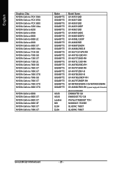
... NVIDIA Geforce 6600 GT NVIDIA Geforce 6600 GT NVIDIA Geforce 6800 GT NVIDIA Geforce 7600 GT NVIDIA Geforce 7900 GT Maker GIGABYTE GIGABYTE GIGABYTE GIGABYTE GIGABYTE GIGABYTE GIGABYTE GIGABYTE GIGABYTE GIGABYTE GIGABYTE GIGABYTE GIGABYTE GIGABYTE GIGABYTE GIGABYTE GIGABYTE GIGABYTE GIGABYTE GIGABYTE GIGABYTE GIGABYTE GIGABYTE ASUS ASUS Leadtek MSI ELSA ELSA Model Name GV-NX53128D GV-NX57128D GV-NX59128D GV-NX55128DP GV-NX62128D GV-NX65128DE GV... above is recommended) EN6600/TD/128 EN6600GT/TD/128 WinFast PX6600GT TDH NX6800GT-TD256E GLADIAC 760GT GLADIAC 790GT GA-G33M-S2H Motherboard - 20 -
... NVIDIA Geforce 6600 GT NVIDIA Geforce 6600 GT NVIDIA Geforce 6800 GT NVIDIA Geforce 7600 GT NVIDIA Geforce 7900 GT Maker GIGABYTE GIGABYTE GIGABYTE GIGABYTE GIGABYTE GIGABYTE GIGABYTE GIGABYTE GIGABYTE GIGABYTE GIGABYTE GIGABYTE GIGABYTE GIGABYTE GIGABYTE GIGABYTE GIGABYTE GIGABYTE GIGABYTE GIGABYTE GIGABYTE GIGABYTE GIGABYTE ASUS ASUS Leadtek MSI ELSA ELSA Model Name GV-NX53128D GV-NX57128D GV-NX59128D GV-NX55128DP GV-NX62128D GV-NX65128DE GV... above is recommended) EN6600/TD/128 EN6600GT/TD/128 WinFast PX6600GT TDH NX6800GT-TD256E GLADIAC 760GT GLADIAC 790GT GA-G33M-S2H Motherboard - 20 -
Manual
Page 22
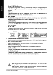
...as an USB keyboard/mouse, USB printer, USB flash drive and etc. Line In Jack (Blue) The default line in a 7.1-channel audio configuration. GA-G33M-S2H Motherboard - 22 - eSATA 3Gb/s Port The eSATA 3Gb/s port supported by the ICH9 South Bridge conforms to connect an external SATA device or a SATA ... Optical S/PDIF Out Connector This connector provides digital audio out to an external audio system that your device and then remove it from the motherboard. • When removing the cable, pull it side to side to prevent an electrical short inside the cable connector. RJ-45 LAN ...
...as an USB keyboard/mouse, USB printer, USB flash drive and etc. Line In Jack (Blue) The default line in a 7.1-channel audio configuration. GA-G33M-S2H Motherboard - 22 - eSATA 3Gb/s Port The eSATA 3Gb/s port supported by the ICH9 South Bridge conforms to connect an external SATA device or a SATA ... Optical S/PDIF Out Connector This connector provides digital audio out to an external audio system that your device and then remove it from the motherboard. • When removing the cable, pull it side to side to prevent an electrical short inside the cable connector. RJ-45 LAN ...
Manual
Page 23
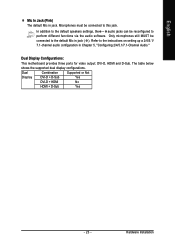
... - In addition to the default speakers settings, the ~ audio jacks can be connected to perform different functions via the audio software. Dual Display Configurations: This motherboard provides three ports for video output: DVI-D, HDMI and D-Sub. Hardware Installation Microphones must be connected to the instructions on setting up a 2/4/5.1/ 7.1-channel audio configuration...
... - In addition to the default speakers settings, the ~ audio jacks can be connected to perform different functions via the audio software. Dual Display Configurations: This motherboard provides three ports for video output: DVI-D, HDMI and D-Sub. Hardware Installation Microphones must be connected to the instructions on setting up a 2/4/5.1/ 7.1-channel audio configuration...
Manual
Page 24
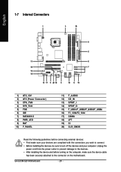
...) SPDIF_O 15) F_USB1/F_USB2/F_USB3/F_USB4 16) F1_1394/F2_1394 17) COMA 18) LPT 19) CI 20) CLR_CMOS Read the following guidelines before turning on the motherboard. GA-G33M-S2H Motherboard - 24 -
...) SPDIF_O 15) F_USB1/F_USB2/F_USB3/F_USB4 16) F1_1394/F2_1394 17) COMA 18) LPT 19) CI 20) CLR_CMOS Read the following guidelines before turning on the motherboard. GA-G33M-S2H Motherboard - 24 -
Manual
Page 25
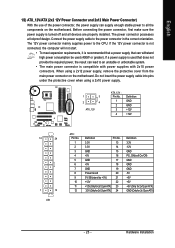
...supply cable into pins under the protective cover when using a 2x12 power supply, remove the protective cover from the main power connector on the motherboard. If the 12V power connector is not connected, the computer will not start. • To meet expansion requirements, it is turned off and... all the components on the motherboard. English 1/2) ATX_12V/ATX (2x2 12V Power Connector and 2x12 Main Power Connector) With the use of the power connector, the power supply can...
...supply cable into pins under the protective cover when using a 2x12 power supply, remove the protective cover from the main power connector on the motherboard. If the 12V power connector is not connected, the computer will not start. • To meet expansion requirements, it is turned off and... all the components on the motherboard. English 1/2) ATX_12V/ATX (2x2 12V Power Connector and 2x12 Main Power Connector) With the use of the power connector, the power supply can...
Manual
Page 26
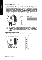
English 3/4) CPU_FAN/SYS_FAN (Fan Headers) The motherboard has a 4-pin CPU fan header (CPU_FAN) and a 4-pin system fan header (SYS_FAN). Overheating may result in the correct orientation. Before connecting a floppy disk drive, locate ... floppy disk drives supported are: 360 KB, 720 KB, 1.2 MB, 1.44 MB, and 2.88 MB. Do not place a jumper cap on the connector. 34 33 2 1 GA-G33M-S2H Motherboard - 26 - Most fans are not configuration jumper blocks. For optimum heat dissipation, it in damage to prevent your CPU and system from overheating. The black...
English 3/4) CPU_FAN/SYS_FAN (Fan Headers) The motherboard has a 4-pin CPU fan header (CPU_FAN) and a 4-pin system fan header (SYS_FAN). Overheating may result in the correct orientation. Before connecting a floppy disk drive, locate ... floppy disk drives supported are: 360 KB, 720 KB, 1.2 MB, 1.44 MB, and 2.88 MB. Do not place a jumper cap on the connector. 34 33 2 1 GA-G33M-S2H Motherboard - 26 - Most fans are not configuration jumper blocks. For optimum heat dissipation, it in damage to prevent your CPU and system from overheating. The black...


