Manual
Page 1
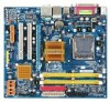
GA-G31MX-S2 LGA775 socket motherboard for Intel® CoreTM processor family/ Intel® Pentium® processor family/Intel® Celeron® processor family User's Manual Rev. 1002 12ME-G31MXS2-1002R * The WEEE marking on the product indicates this product must not be disposed of with user's other household waste and must be handed over to a designated collection point for the recycling of waste electrical and electronic equipment!! * The WEEE marking applies only in European Union's member states.
GA-G31MX-S2 LGA775 socket motherboard for Intel® CoreTM processor family/ Intel® Pentium® processor family/Intel® Celeron® processor family User's Manual Rev. 1002 12ME-G31MXS2-1002R * The WEEE marking on the product indicates this product must not be disposed of with user's other household waste and must be handed over to a designated collection point for the recycling of waste electrical and electronic equipment!! * The WEEE marking applies only in European Union's member states.
Manual
Page 3
... protected by copyright laws and is exclusively licensed to use GIGABYTE's unique features, read the User's Manual. „ For instructions on how to GIGABYTE UNITED INC. Example: GIGABYTE UNITED INC. For product-related information, check on our website at: http://www.gigabyte.com.tw Identifying Your Motherboard Revision The revision number on our website. All rights...
... protected by copyright laws and is exclusively licensed to use GIGABYTE's unique features, read the User's Manual. „ For instructions on how to GIGABYTE UNITED INC. Example: GIGABYTE UNITED INC. For product-related information, check on our website at: http://www.gigabyte.com.tw Identifying Your Motherboard Revision The revision number on our website. All rights...
Manual
Page 6
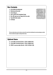
Box Contents GA-G31MX-S2 motherboard Motherboard driver disk User's Manual Intel® LGA775 CPU Installation Guide One IDE cable and one floppy disk drive cable Two SATA 3Gb/s cables I/O Shield The box contents above are subject to change without notice. The box contents are for reference only and the actual items shall depend on product package you obtain. Optional Items 2-port USB 2.0 bracket (Part No. 12CR1-1UB030-51/R) 4-port USB 2.0 bracket (Part No. 12CR1-1UB030-21/R) S/PDIF in and out cable (Part No. 12CR1-1SPINO-11/R) - 6 -
Box Contents GA-G31MX-S2 motherboard Motherboard driver disk User's Manual Intel® LGA775 CPU Installation Guide One IDE cable and one floppy disk drive cable Two SATA 3Gb/s cables I/O Shield The box contents above are subject to change without notice. The box contents are for reference only and the actual items shall depend on product package you obtain. Optional Items 2-port USB 2.0 bracket (Part No. 12CR1-1UB030-51/R) 4-port USB 2.0 bracket (Part No. 12CR1-1UB030-21/R) S/PDIF in and out cable (Part No. 12CR1-1SPINO-11/R) - 6 -
Manual
Page 9
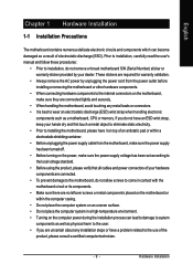
... environment. • Turning on the computer power during the installation process can become damaged as a motherboard, CPU or memory. Prior to installation, carefully read the user's manual and follow these procedures: • Prior to installation, do not allow screws to come in contact... with the motherboard circuit or its components. • Make sure there are no leftover screws or metal components placed on the motherboard or within a electrostatic...
... environment. • Turning on the computer power during the installation process can become damaged as a motherboard, CPU or memory. Prior to installation, carefully read the user's manual and follow these procedures: • Prior to installation, do not allow screws to come in contact... with the motherboard circuit or its components. • Make sure there are no leftover screws or metal components placed on the motherboard or within a electrostatic...

Manual
Page 15
Check that the Male and Female push pins are joined closely. (Refer to your CPU cooler installation manual for instructions on the motherboard. Step 6: Finally, attach the power connector of the CPU cooler to the CPU fan header (CPU_FAN) on installing the cooler.) Step 5: After ...CPU may damage the CPU. - 15 - English 1-3-2 Installing the CPU Cooler Follow the steps below to correctly install the CPU cooler on the motherboard. (The following procedure uses Intel® boxed cooler as the picture above, the installation is complete. Inadequately removing the CPU cooler may adhere to...
Check that the Male and Female push pins are joined closely. (Refer to your CPU cooler installation manual for instructions on the motherboard. Step 6: Finally, attach the power connector of the CPU cooler to the CPU fan header (CPU_FAN) on installing the cooler.) Step 5: After ...CPU may damage the CPU. - 15 - English 1-3-2 Installing the CPU Cooler Follow the steps below to correctly install the CPU cooler on the motherboard. (The following procedure uses Intel® boxed cooler as the picture above, the installation is complete. Inadequately removing the CPU cooler may adhere to...
Manual
Page 18
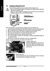
...are completely inserted into the PCI Express x16 slot. Make sure the graphics card is fully seated in the slot. 3. GA-G31MX-S2 Motherboard - 18 - Carefully read the manual that supports your card. Remove the metal slot cover from the slot. Secure the card's metal bracket to make any ... Express x16 Slot PCI Slot PCI Express x4 Slot Follow the steps below to install an expansion card: • Make sure the motherboard supports the expansion card. English 1-5 Installing an Expansion Card Read the following guidelines before installing an expansion card to release the card ...
...are completely inserted into the PCI Express x16 slot. Make sure the graphics card is fully seated in the slot. 3. GA-G31MX-S2 Motherboard - 18 - Carefully read the manual that supports your card. Remove the metal slot cover from the slot. Secure the card's metal bracket to make any ... Express x16 Slot PCI Slot PCI Express x4 Slot Follow the steps below to install an expansion card: • Make sure the motherboard supports the expansion card. English 1-5 Installing an Expansion Card Read the following guidelines before installing an expansion card to release the card ...

Manual
Page 29
... (Clearing CMOS Jumper) Use this jumper to touch the two pins for BIOS configurations). 16) CI (Chassis Intrusion Header) This motherboard provides a chassis detection feature that detects if the chassis cover has been removed. This function requires a chassis with chassis intrusion detection... cord from the jumper. Failure to do so may cause damage to the motherboard. • After system restart, go to BIOS Setup to load factory defaults (select Load Optimized Defaults) or manually configure the BIOS settings (refer to factory defaults. date information and BIOS configurations...
... (Clearing CMOS Jumper) Use this jumper to touch the two pins for BIOS configurations). 16) CI (Chassis Intrusion Header) This motherboard provides a chassis detection feature that detects if the chassis cover has been removed. This function requires a chassis with chassis intrusion detection... cord from the jumper. Failure to do so may cause damage to the motherboard. • After system restart, go to BIOS Setup to load factory defaults (select Load Optimized Defaults) or manually configure the BIOS settings (refer to factory defaults. date information and BIOS configurations...
Manual
Page 36
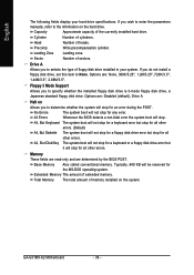
...to determine whether the system will not stop . Sector Number of memory installed on Allows you wish to enter the parameters manually, refer to None. No Errors All Errors The system boot will stop for all other errors. Whenever the BIOS detects...stop for any error. Extended Memory The amount of cylinders. Cylinder Number of extended memory. Precomp Write precompensation cylinder. Halt on the system. GA-G31MX-S2 Motherboard - 36 - Options are : None, 360K/5.25", 1.2M/5.25", 720K/3.5", 1.44M/3.5", 2.88M/3.5". All, But Keyboard The system boot ...
...to determine whether the system will not stop . Sector Number of memory installed on Allows you wish to enter the parameters manually, refer to None. No Errors All Errors The system boot will stop for all other errors. Whenever the BIOS detects...stop for any error. Extended Memory The amount of cylinders. Cylinder Number of extended memory. Precomp Write precompensation cylinder. Halt on the system. GA-G31MX-S2 Motherboard - 36 - Options are : None, 360K/5.25", 1.2M/5.25", 720K/3.5", 1.44M/3.5", 2.88M/3.5". All, But Keyboard The system boot ...
Manual
Page 40
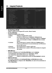
...and PATA IDE Set to operate in SATA mode. When PATA IDE Set to is automatically configured to Combined mode, you can manually re-configure it to Enhanced mode as needed. (Default) Combined Sets all SATA devices to settings. If your onboard SATA .... SATA Port 0/2 Set to Ch. 1 Master/Slave, this option will be used simultaneously: two PATA devices Enhanced plus two SATA devices. GA-G31MX-S2 Motherboard - 40 - English 2-5 Integrated Peripherals CMOS Setup Utility-Copyright (C) 1984-2007 Award Software Integrated Peripherals On-Chip Primary PCI IDE On-Chip SATA...
...and PATA IDE Set to operate in SATA mode. When PATA IDE Set to is automatically configured to Combined mode, you can manually re-configure it to Enhanced mode as needed. (Default) Combined Sets all SATA devices to settings. If your onboard SATA .... SATA Port 0/2 Set to Ch. 1 Master/Slave, this option will be used simultaneously: two PATA devices Enhanced plus two SATA devices. GA-G31MX-S2 Motherboard - 40 - English 2-5 Integrated Peripherals CMOS Setup Utility-Copyright (C) 1984-2007 Award Software Integrated Peripherals On-Chip Primary PCI IDE On-Chip SATA...
Manual
Page 48
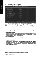
... Optimized System Voltage Control DDR2 OverVoltage Control FSB OverVoltage Control CPU Voltage Control Normal CPU Vcore ******** [Auto] [16X] [Disabled] 266 [Auto] [Standard] [Auto] 667 [Option 1] [Manual] [Normal] [Normal] [Normal] 1.4000V Item Help Menu Level` KLJI: Move Enter: Select F5: Previous Values +/-/PU/PD: Value F10: Save F6: Fail-Safe Defaults ESC... clock ratio for automated system reboot, or clear the CMOS values to reset the board to enhance the performance of the graphics chip and memory. GA-G31MX-S2 Motherboard - 48 -
... Optimized System Voltage Control DDR2 OverVoltage Control FSB OverVoltage Control CPU Voltage Control Normal CPU Vcore ******** [Auto] [16X] [Disabled] 266 [Auto] [Standard] [Auto] 667 [Option 1] [Manual] [Normal] [Normal] [Normal] 1.4000V Item Help Menu Level` KLJI: Move Enter: Select F5: Previous Values +/-/PU/PD: Value F10: Save F6: Fail-Safe Defaults ESC... clock ratio for automated system reboot, or clear the CMOS values to reset the board to enhance the performance of the graphics chip and memory. GA-G31MX-S2 Motherboard - 48 -
Manual
Page 57
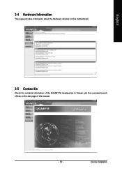
Drivers Installation English 3-4 Hardware Information This page provides information about the hardware devices on this motherboard. 3-5 Contact Us Check the contacts information of the GIGABYTE headquarter in Taiwan and the overseas branch offices on the last page of this manual. - 57 -
Drivers Installation English 3-4 Hardware Information This page provides information about the hardware devices on this motherboard. 3-5 Contact Us Check the contacts information of the GIGABYTE headquarter in Taiwan and the overseas branch offices on the last page of this manual. - 57 -
Manual
Page 68
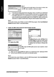
...Setup program. Select Load Optimized Defaults and press to enter the BIOS Setup program. GA-G31MX-S2 Motherboard - 68 - English Step 3: First make sure the model name on the @BIOS server site, please manually download the BIOS update file from the Internet or through other Step 3: source. ... file could result in Step 1: Click Update New BIOS. Upon completion, restart your motherboard model. Update the BIOS without Using the Internet Update Function" below. f1) obtained from GIGABYTE's website and follow the instructions in "Update the BIOS without Using the Internet Update ...
...Setup program. Select Load Optimized Defaults and press to enter the BIOS Setup program. GA-G31MX-S2 Motherboard - 68 - English Step 3: First make sure the model name on the @BIOS server site, please manually download the BIOS update file from the Internet or through other Step 3: source. ... file could result in Step 1: Click Update New BIOS. Upon completion, restart your motherboard model. Update the BIOS without Using the Internet Update Function" below. f1) obtained from GIGABYTE's website and follow the instructions in "Update the BIOS without Using the Internet Update ...
Manual
Page 71
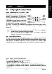
...(Note) 2/4/5.1/7.1 Channel Audio Configurations: Refer to the right shows the default audio jack assignments. Side Speaker Out Mic In For example, in jack and manually configure the jack for multi-channel speaker configurations. • 2 channel audio: Headphone or Line out. • 4 channel audio: Front speaker out..., you can listen to be simultaneously processed. English Chapter 5 Appendix 5-1 Configuring Audio Input and Output 5-1-1 Configuring 2/4/5.1/7.1-Channel Audio The motherboard provides six audio jacks on the back panel which support 2/4/5.1/7.1-channel audio.
...(Note) 2/4/5.1/7.1 Channel Audio Configurations: Refer to the right shows the default audio jack assignments. Side Speaker Out Mic In For example, in jack and manually configure the jack for multi-channel speaker configurations. • 2 channel audio: Headphone or Line out. • 4 channel audio: Front speaker out..., you can listen to be simultaneously processed. English Chapter 5 Appendix 5-1 Configuring Audio Input and Output 5-1-1 Configuring 2/4/5.1/7.1-Channel Audio The motherboard provides six audio jacks on the back panel which support 2/4/5.1/7.1-channel audio.


