Manual
Page 4
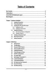
Table of Contents Box Contents ...6 OptionalItems ...6 GA-G31MX-S2 Motherboard Layout 7 Block Diagram ...8 Chapter 1 Hardware Installation 9 1-1 Installation Precautions 9 1-2 Product Specifications 10 1-3 Installing the CPU and CPU Cooler 13 1-3-1 Installing the CPU 13 1-3-2 Installing the CPU Cooler 15 1-4 Installing the Memory 16 1-4-1 Dual Channel Memory Configuration 16 1-4-2 Installing a Memory 17 1-5 Installing an Expansion Card 18 1-6 Back Panel Connectors 19...
Table of Contents Box Contents ...6 OptionalItems ...6 GA-G31MX-S2 Motherboard Layout 7 Block Diagram ...8 Chapter 1 Hardware Installation 9 1-1 Installation Precautions 9 1-2 Product Specifications 10 1-3 Installing the CPU and CPU Cooler 13 1-3-1 Installing the CPU 13 1-3-2 Installing the CPU Cooler 15 1-4 Installing the Memory 16 1-4-1 Dual Channel Memory Configuration 16 1-4-2 Installing a Memory 17 1-5 Installing an Expansion Card 18 1-6 Back Panel Connectors 19...
Manual
Page 6
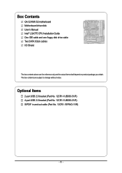
Optional Items 2-port USB 2.0 bracket (Part No. 12CR1-1UB030-51/R) 4-port USB 2.0 bracket (Part No. 12CR1-1UB030-21/R) S/PDIF in and out cable (Part No. 12CR1-1SPINO-11/R) - 6 - Box Contents GA-G31MX-S2 motherboard Motherboard driver disk User's Manual Intel® LGA775 CPU Installation Guide One IDE cable and one floppy disk drive cable Two SATA 3Gb/s cables I/O Shield The box contents above are subject to change without notice. The box contents are for reference only and the actual items shall depend on product package you obtain.
Optional Items 2-port USB 2.0 bracket (Part No. 12CR1-1UB030-51/R) 4-port USB 2.0 bracket (Part No. 12CR1-1UB030-21/R) S/PDIF in and out cable (Part No. 12CR1-1SPINO-11/R) - 6 - Box Contents GA-G31MX-S2 motherboard Motherboard driver disk User's Manual Intel® LGA775 CPU Installation Guide One IDE cable and one floppy disk drive cable Two SATA 3Gb/s cables I/O Shield The box contents above are subject to change without notice. The box contents are for reference only and the actual items shall depend on product package you obtain.
Manual
Page 8
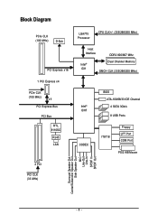
Block Diagram PCIe CLK (100 MHz) D-Sub PCI Express x16 1 PCI Express x4 PCIe CLK (100 MHz) x4 PCI Express Bus PCI Bus RTL 8110SC RJ45 LAN LGA775 Processor CPU CLK+/- (333/266/200 MHz) Host Interface DDR2 800/667 MHz Intel® G31 Dual Channel Memory GMCH CLK (333/266/200 MHz) Intel® ICH7 CODEC BIOS ATA-100/66/33 IDE Channel 4 SATA 3Gb/s 8 USB Ports IT8718 Floppy LPT Port COM Port PS/2 KB/Mouse 2 PCI PCI CLK (33 MHz) Surround Speaker Out Center/Subwoofer Speaker Out Side Speaker Out MIC Line-Out Line-In SPDIF In SPDIF Out - 8 -
Block Diagram PCIe CLK (100 MHz) D-Sub PCI Express x16 1 PCI Express x4 PCIe CLK (100 MHz) x4 PCI Express Bus PCI Bus RTL 8110SC RJ45 LAN LGA775 Processor CPU CLK+/- (333/266/200 MHz) Host Interface DDR2 800/667 MHz Intel® G31 Dual Channel Memory GMCH CLK (333/266/200 MHz) Intel® ICH7 CODEC BIOS ATA-100/66/33 IDE Channel 4 SATA 3Gb/s 8 USB Ports IT8718 Floppy LPT Port COM Port PS/2 KB/Mouse 2 PCI PCI CLK (33 MHz) Surround Speaker Out Center/Subwoofer Speaker Out Side Speaker Out MIC Line-Out Line-In SPDIF In SPDIF Out - 8 -
Manual
Page 9
... delicate electronic circuits and components which can lead to damage to wear an electrostatic discharge (ESD) wrist strap when handling electronic components such as a motherboard, CPU or memory. Prior to installation, carefully read the user's manual and follow these procedures: • Prior to installation, do not remove or break motherboard S/N (Serial...
... delicate electronic circuits and components which can lead to damage to wear an electrostatic discharge (ESD) wrist strap when handling electronic components such as a motherboard, CPU or memory. Prior to installation, carefully read the user's manual and follow these procedures: • Prior to installation, do not remove or break motherboard S/N (Serial...
Manual
Page 10
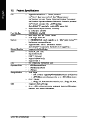
...; Pentium® 4 processor/ Intel® Celeron® processor in the LGA 775 package (Go to GIGABYTE's website for the latest CPU support list.) Š Support for Intel® Hyper-Threading Technology Š L2 cache varies with CPU Š 1333/1066/800 MHz FSB Š North Bridge: Intel® G31 Express Chipset Š South... Š Integrated in the South Bridge Š Up to 8 USB 2.0/1.1 ports (4 on the back panel, 4 via the USB brackets connected to the internal USB headers) GA-G31MX-S2 Motherboard - 10 -
...; Pentium® 4 processor/ Intel® Celeron® processor in the LGA 775 package (Go to GIGABYTE's website for the latest CPU support list.) Š Support for Intel® Hyper-Threading Technology Š L2 cache varies with CPU Š 1333/1066/800 MHz FSB Š North Bridge: Intel® G31 Express Chipset Š South... Š Integrated in the South Bridge Š Up to 8 USB 2.0/1.1 ports (4 on the back panel, 4 via the USB brackets connected to the internal USB headers) GA-G31MX-S2 Motherboard - 10 -
Manual
Page 11
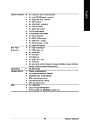
...138; 1 x 4-pin ATX 12V power connector Š 1 x floppy disk drive connector Š 1 x IDE connector Š 4 x SATA 3Gb/s connectors Š 1 x CPU fan header Š 1 x system fan header Š 1 x front panel header Š 1 x front panel audio header Š 1 x CD In connector Š 1 x... Š iTE IT8718 chip Hardware Monitor Š System voltage detection Š CPU/System temperature detection Š CPU/System fan speed detection Š CPU overheating warning Š CPU/System fan fail warning Š CPU fan speed control BIOS Š 1 x 4 Mbit flash Š Use ...
...138; 1 x 4-pin ATX 12V power connector Š 1 x floppy disk drive connector Š 1 x IDE connector Š 4 x SATA 3Gb/s connectors Š 1 x CPU fan header Š 1 x system fan header Š 1 x front panel header Š 1 x front panel audio header Š 1 x CD In connector Š 1 x... Š iTE IT8718 chip Hardware Monitor Š System voltage detection Š CPU/System temperature detection Š CPU/System fan speed detection Š CPU overheating warning Š CPU/System fan fail warning Š CPU fan speed control BIOS Š 1 x 4 Mbit flash Š Use ...

Manual
Page 13
... you begin to install the CPU: • Make sure that the motherboard supports the CPU. (Go to GIGABYTE's website for the latest CPU support list.) • Always turn on the computer if the CPU cooler is not recom- English 1-3 Installing the CPU and CPU Cooler Read the following guidelines... before installing the CPU to prevent hardware damage. &#...
... you begin to install the CPU: • Make sure that the motherboard supports the CPU. (Go to GIGABYTE's website for the latest CPU support list.) • Always turn on the computer if the CPU cooler is not recom- English 1-3 Installing the CPU and CPU Cooler Read the following guidelines... before installing the CPU to prevent hardware damage. &#...

Manual
Page 14
... to prevent damage to correctly install the CPU into its locked position. GA-G31MX-S2 Motherboard - 14 - Align the CPU pin one marking (triangle) with the pin one corner of the CPU socket (or you may align the CPU notches with your thumb and index fingers. CPU Socket Lever Step 1: Completely raise the CPU socket lever. Step 4: Hold the...
... to prevent damage to correctly install the CPU into its locked position. GA-G31MX-S2 Motherboard - 14 - Align the CPU pin one marking (triangle) with the pin one corner of the CPU socket (or you may align the CPU notches with your thumb and index fingers. CPU Socket Lever Step 1: Completely raise the CPU socket lever. Step 4: Hold the...

Manual
Page 15
...joined closely. (Refer to install.) Step 3: Place the cooler atop the CPU, aligning the four push pins through the pin holes on the motherboard. Inadequately removing the CPU cooler may adhere to the CPU fan header (CPU_FAN) on the motherboard. Hardware Installation Direction of the ... Step 4: You should hear a "click" when pushing down on the push pins diagonally. English 1-3-2 Installing the CPU Cooler Follow the steps below to correctly install the CPU cooler on the motherboard. (The following procedure uses Intel® boxed cooler as the picture above, the installation is...
...joined closely. (Refer to install.) Step 3: Place the cooler atop the CPU, aligning the four push pins through the pin holes on the motherboard. Inadequately removing the CPU cooler may adhere to the CPU fan header (CPU_FAN) on the motherboard. Hardware Installation Direction of the ... Step 4: You should hear a "click" when pushing down on the push pins diagonally. English 1-3-2 Installing the CPU Cooler Follow the steps below to correctly install the CPU cooler on the motherboard. (The following procedure uses Intel® boxed cooler as the picture above, the installation is...
Manual
Page 22
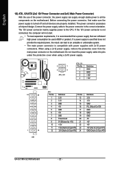
... 3.3V -12V GND PS_ON(soft On/Off) GND GND GND -5V +5V +5V +5V (Only for 2x12-pin ATX) GND (Only for 2x12-pin ATX) GA-G31MX-S2 Motherboard - 22 - Do not insert the power supply cable into pins under the protective cover when using a 2x12 power supply, remove the protective cover from... all devices are properly installed. If a power supply is turned off and all the components on the motherboard. Connect the power supply cable to the CPU. Before connecting the power connector, first make sure the power supply is used (400W or greater).
... 3.3V -12V GND PS_ON(soft On/Off) GND GND GND -5V +5V +5V +5V (Only for 2x12-pin ATX) GND (Only for 2x12-pin ATX) GA-G31MX-S2 Motherboard - 22 - Do not insert the power supply cable into pins under the protective cover when using a 2x12 power supply, remove the protective cover from... all devices are properly installed. If a power supply is turned off and all the components on the motherboard. Connect the power supply cable to the CPU. Before connecting the power connector, first make sure the power supply is used (400W or greater).
Manual
Page 23
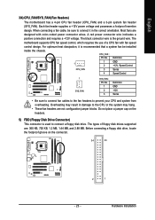
... designed with fan speed control design. For optimum heat dissipation, it is recommended that a system fan be sure to connect it in damage to the CPU or the system may hang. • These fan headers are : 360 KB, 720 KB, 1.2 MB, 1.44 MB, and 2.88 MB. Do not ...5) FDD (Floppy Disk Drive Connector) This connector is the ground wire. The black connector wire is used to prevent your CPU and system from overheating. The motherboard supports CPU fan speed control, which requires the use of floppy disk drives supported are not configuration jumper blocks. When connecting a fan ...
... designed with fan speed control design. For optimum heat dissipation, it is recommended that a system fan be sure to connect it in damage to the CPU or the system may hang. • These fan headers are : 360 KB, 720 KB, 1.2 MB, 1.44 MB, and 2.88 MB. Do not ...5) FDD (Floppy Disk Drive Connector) This connector is the ground wire. The black connector wire is used to prevent your CPU and system from overheating. The motherboard supports CPU fan speed control, which requires the use of floppy disk drives supported are not configuration jumper blocks. When connecting a fan ...
Manual
Page 34
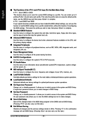
...BIOS default settings, you to view the BIOS settings but not to the CMOS and exit BIOS Setup. (Pressing can also carry out this task.) GA-G31MX-S2 Motherboard - 34 - First select the profile you wish to load, then press to complete. „ Standard CMOS Features Use this menu to ... that stop the system boot, etc. „ Advanced BIOS Features Use this menu to configure the device boot order, advanced features available on the CPU, and the primary display adapter. „ Integrated Peripherals Use this menu to configure all peripheral devices, such as IDE, SATA, USB, integrated audio...
...BIOS default settings, you to view the BIOS settings but not to the CMOS and exit BIOS Setup. (Pressing can also carry out this task.) GA-G31MX-S2 Motherboard - 34 - First select the profile you wish to load, then press to complete. „ Standard CMOS Features Use this menu to ... that stop the system boot, etc. „ Advanced BIOS Features Use this menu to configure the device boot order, advanced features available on the CPU, and the primary display adapter. „ Integrated Peripherals Use this menu to configure all peripheral devices, such as IDE, SATA, USB, integrated audio...

Manual
Page 37
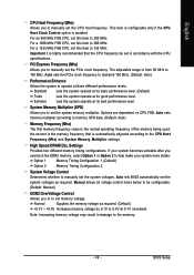
...support multi-processors mode. (Default: Enabled) (Note) This item is required every time the system boots, or only when you install a CPU that supports this feature. Password Check Specifies whether a password is present only if you enter BIOS Setup. After configuring this menu when finished... and to exit this item, set the password(s) under the Set Supervisor/User Password item in the BIOS Main Menu. BIOS Setup Capability CPU Hyper-Threading (Note) Limit CPUID Max. For more information about Intel CPUs' unique features, please visit Intel's website. - 37 - ...
...support multi-processors mode. (Default: Enabled) (Note) This item is required every time the system boots, or only when you install a CPU that supports this feature. Password Check Specifies whether a password is present only if you enter BIOS Setup. After configuring this menu when finished... and to exit this item, set the password(s) under the Set Supervisor/User Password item in the BIOS Main Menu. BIOS Setup Capability CPU Hyper-Threading (Note) Limit CPUID Max. For more information about Intel CPUs' unique features, please visit Intel's website. - 37 - ...
Manual
Page 38
... Halt (C1E) (Note) Enables or disables Intel® CPU Enhanced Halt (C1E) function, a CPU power-saving function in independent partitions. set this item to Disabled for the computer, reducing exposure to run multiple operating systems and applications in system halt state. GA-G31MX-S2 Motherboard - 38 - English Limit CPUID Max. to decrease average power consumption...
... Halt (C1E) (Note) Enables or disables Intel® CPU Enhanced Halt (C1E) function, a CPU power-saving function in independent partitions. set this item to Disabled for the computer, reducing exposure to run multiple operating systems and applications in system halt state. GA-G31MX-S2 Motherboard - 38 - English Limit CPUID Max. to decrease average power consumption...
Manual
Page 46
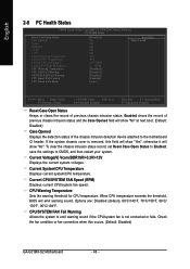
... sound if the CPU/system fan is removed, this occurs. (Default: Disabled) GA-G31MX-S2 Motherboard - 46 - Current System/CPU Temperature Displays current system/CPU temperature. Enabled clears the record of previous chassis intrusion status. CPU Warning Temperature Sets the warning threshold for CPU temperature. English ... Opened Vcore DDR18V +3.3V +12V Current System Temperature Current CPU Temperature Current CPU FAN Speed Current SYSTEM FAN Speed CPU Warning Temperature CPU FAN Fail Warning SYSTEM FAN Fail Warning CPU Smart FAN Control CPU Smart FAN Mode [Disabled] No OK OK OK OK ...
... sound if the CPU/system fan is removed, this occurs. (Default: Disabled) GA-G31MX-S2 Motherboard - 46 - Current System/CPU Temperature Displays current system/CPU temperature. Enabled clears the record of previous chassis intrusion status. CPU Warning Temperature Sets the warning threshold for CPU temperature. English ... Opened Vcore DDR18V +3.3V +12V Current System Temperature Current CPU Temperature Current CPU FAN Speed Current SYSTEM FAN Speed CPU Warning Temperature CPU FAN Fail Warning SYSTEM FAN Fail Warning CPU Smart FAN Control CPU Smart FAN Mode [Disabled] No OK OK OK OK ...
Manual
Page 47
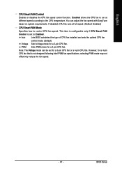
...mode can adjust the fan speed with EasyTune based on system requirements. Enabled allows the CPU fan to run at full speed. (Default: Enabled) CPU Smart FAN Mode Specifies how to control CPU fan speed. If disabled, CPU fan runs at different speed according to Enabled. You can be set for a 4-pin... CPU fan that is set to the CPU temperature. PWM Sets PWM mode for a 3-pin CPU fan. Auto Lets BIOS autodetect the type of CPU fan installed and sets the optimal CPU fan control mode. (Default) Voltage Sets Voltage mode for a 4-...
...mode can adjust the fan speed with EasyTune based on system requirements. Enabled allows the CPU fan to run at full speed. (Default: Enabled) CPU Smart FAN Mode Specifies how to control CPU fan speed. If disabled, CPU fan runs at different speed according to Enabled. You can be set for a 4-pin... CPU fan that is set to the CPU temperature. PWM Sets PWM mode for a 3-pin CPU fan. Auto Lets BIOS autodetect the type of CPU fan installed and sets the optimal CPU fan control mode. (Default) Voltage Sets Voltage mode for a 4-...
Manual
Page 48
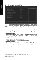
... to Auto to default values. (Default: Disabled) (Note) This item appears only if you install a CPU that you set the R.G.B. Enabled will allow for the installed CPU. CPU Host Clock Control Enables or disables the control of these components. GA-G31MX-S2 Motherboard - 48 - Options are: Auto (default), Fast, Turbo. Robust Graphics Booster Robust Graphics Booster...
... to Auto to default values. (Default: Disabled) (Note) This item appears only if you install a CPU that you set the R.G.B. Enabled will allow for the installed CPU. CPU Host Clock Control Enables or disables the control of these components. GA-G31MX-S2 Motherboard - 48 - Options are: Auto (default), Fast, Turbo. Robust Graphics Booster Robust Graphics Booster...
Manual
Page 49
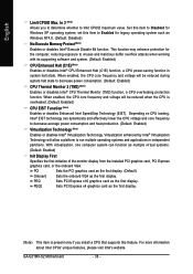
... you to manually set this item to 266 MHz. For a 1066 MHz FSB CPU, set the CPU host frequency. Option 1 Memory Timing Configuration 1. (Default) Option 2 Memory Timing Configuration 2. Options are dependent on CPU FSB. Important It is highly recommended that is automatically adjusted according to 200 MHz.... Note: Increasing memory voltage may result in damage to set in accordance with the CPU specifications. the second is enabled. For an 800 MHz FSB CPU, set the PCIe clock frequency. PCI Express Frequency (Mhz) Allows you to manually set this item...
... you to manually set this item to 266 MHz. For a 1066 MHz FSB CPU, set the CPU host frequency. Option 1 Memory Timing Configuration 1. (Default) Option 2 Memory Timing Configuration 2. Options are dependent on CPU FSB. Important It is highly recommended that is automatically adjusted according to 200 MHz.... Note: Increasing memory voltage may result in damage to set in accordance with the CPU specifications. the second is enabled. For an 800 MHz FSB CPU, set the PCIe clock frequency. PCI Express Frequency (Mhz) Allows you to manually set this item...
Manual
Page 50
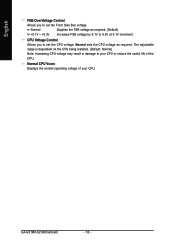
... as required. (Default) Increases FSB voltage by 0.1V to your CPU or reduce the useful life of your CPU. CPU Voltage Control Allows you to set the CPU voltage. Normal CPU Vcore Displays the normal operating voltage of the CPU. GA-G31MX-S2 Motherboard - 50 - Normal +0.1V ~ +0.3V Supplies the FSB voltage as required. The adjustable range is dependent...
... as required. (Default) Increases FSB voltage by 0.1V to your CPU or reduce the useful life of your CPU. CPU Voltage Control Allows you to set the CPU voltage. Normal CPU Vcore Displays the normal operating voltage of the CPU. GA-G31MX-S2 Motherboard - 50 - Normal +0.1V ~ +0.3V Supplies the FSB voltage as required. The adjustable range is dependent...
Manual
Page 69
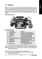
... setting page Enters the PC Health setting page Confirmation and Execution button Toggles between Easy and Advance Mode Displays panel of CPU frequency Shows the information of the current function Visits GIGABYTE website Displays EasyTuneTM 5 help screen Quits or minimizes EasyTuneTM 5 Incorrectly doing overclock/overvoltage may result in damage to enter the...
... setting page Enters the PC Health setting page Confirmation and Execution button Toggles between Easy and Advance Mode Displays panel of CPU frequency Shows the information of the current function Visits GIGABYTE website Displays EasyTuneTM 5 help screen Quits or minimizes EasyTuneTM 5 Incorrectly doing overclock/overvoltage may result in damage to enter the...


