Manual
Page 2
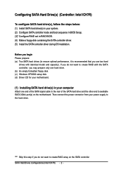
If you do not want to create RAID array on the motherboard. Then connect the power connector from your power supply to available SATA 3Gb/s port(s) on the SATA controller SATA Hard Drives Configurations (Intel ICH7R) - 2 - Ác ...). "*" Skip this step if you may prepare only one hard drive. (b) An empty formatted floppy disk. (c) Windows XP/2000 setup disk. (d) Driver CD for your motherboard. (1) Installing SATA hard drive(s) in RAID BIOS. (4) Make a floppy disk containing the SATA controller driver. (5) Install the SATA controller driver during OS installation.
If you do not want to create RAID array on the motherboard. Then connect the power connector from your power supply to available SATA 3Gb/s port(s) on the SATA controller SATA Hard Drives Configurations (Intel ICH7R) - 2 - Ác ...). "*" Skip this step if you may prepare only one hard drive. (b) An empty formatted floppy disk. (c) Windows XP/2000 setup disk. (d) Driver CD for your motherboard. (1) Installing SATA hard drive(s) in RAID BIOS. (4) Make a floppy disk containing the SATA controller driver. (5) Install the SATA controller driver during OS installation.
Manual
Page 3
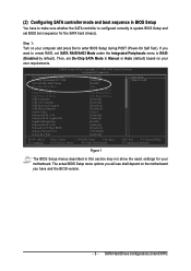
...Exit F1: General Help F7: Optimized Defaults Figure 1 The BIOS Setup menus described in system BIOS Setup and set BIOS boot sequence for your motherboard. If you have to make sure whether the SATA controller is configured correctly in this section may not show the exact settings for the SATA... - Then, set SATA RAID/AHCI Mode under the Integrated Peripherals menu to enter BIOS Setup during POST (Power-On Self Test). Step 1: Turn on the motherboard you want to create RAID, set On-Chip SATA Mode to Manual or Auto (default) based on your computer and press Del to RAID (Disabled...
...Exit F1: General Help F7: Optimized Defaults Figure 1 The BIOS Setup menus described in system BIOS Setup and set BIOS boot sequence for your motherboard. If you have to make sure whether the SATA controller is configured correctly in this section may not show the exact settings for the SATA... - Then, set SATA RAID/AHCI Mode under the Integrated Peripherals menu to enter BIOS Setup during POST (Power-On Self Test). Step 1: Turn on the motherboard you want to create RAID, set On-Chip SATA Mode to Manual or Auto (default) based on your computer and press Del to RAID (Disabled...
Manual
Page 9
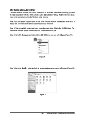
... during OS installation. The installation utility will appear automatically. The instructions below explain how to a floppy disk. Step 1: Find an available system and insert the motherboard driver CD into the CD-ROM drive. First of all, you need to copy the driver for the SATA controller from the... motherboard driver CD to copy the driver. (4) Making a SATA Driver Disk To install Windows 2000/XP onto a SATA hard drives on the ICH6R controller successfully, you ...
... during OS installation. The installation utility will appear automatically. The instructions below explain how to a floppy disk. Step 1: Find an available system and insert the motherboard driver CD into the CD-ROM drive. First of all, you need to copy the driver for the SATA controller from the... motherboard driver CD to copy the driver. (4) Making a SATA Driver Disk To install Windows 2000/XP onto a SATA hard drives on the ICH6R controller successfully, you ...
Manual
Page 10
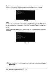
...-click MENU.exe. An MS-DOS prompt screen similar to Figure 13 below will take about one minute to copy the SATA driver from the motherboard driver CD to select 7) Intel(R) Matrix Storage Manager 32bit. SATA Hard Drives Configurations (Intel ICH7R) - 10 -
...-click MENU.exe. An MS-DOS prompt screen similar to Figure 13 below will take about one minute to copy the SATA driver from the motherboard driver CD to select 7) Intel(R) Matrix Storage Manager 32bit. SATA Hard Drives Configurations (Intel ICH7R) - 10 -

Manual
Page 12
... use with Windows, including those for which you have a device support disk from a mass storage device manufacturer, press S. * If you do not want from the motherboard driver CD. Step 4: When the screen as shown below Åé will begin to load the SATA driver from the floppy disk. SATA Hard Drives...
... use with Windows, including those for which you have a device support disk from a mass storage device manufacturer, press S. * If you do not want from the motherboard driver CD. Step 4: When the screen as shown below Åé will begin to load the SATA driver from the floppy disk. SATA Hard Drives...
Manual
Page 1
GA-G1975X Intel® Pentium® Processor Extreme Edition Intel® Pentium® D / Pentium® 4 LGA775 Processor Motherboard User's Manual Rev. 1005 12ME-G1975X-1005R * The WEEE marking on the product indicates this product must not be disposed of with user's other household waste and must be handed over to a designated collection point for the recycling of waste electrical and electronic equipment!! * The WEEE marking applies only in European Union's member states.
GA-G1975X Intel® Pentium® Processor Extreme Edition Intel® Pentium® D / Pentium® 4 LGA775 Processor Motherboard User's Manual Rev. 1005 12ME-G1975X-1005R * The WEEE marking on the product indicates this product must not be disposed of with user's other household waste and must be handed over to a designated collection point for the recycling of waste electrical and electronic equipment!! * The WEEE marking applies only in European Union's member states.
Manual
Page 2
Motherboard GA-G1975X Dec. 16, 2005 Motherboard GA-G1975X Dec. 16, 2005
Motherboard GA-G1975X Dec. 16, 2005 Motherboard GA-G1975X Dec. 16, 2005
Manual
Page 4
Table of Contents ItemChecklist ...6 GA-G1975X Motherboard Layout 7 Block Diagram ...8 Chapter 1 Hardware Installation 9 1-1 Considerations Prior to Installation 9 1-2 Feature Summary 10 1-3 Installation of the CPU and Heatsink 13 1-3-1 Installation of the CPU 13 1-3-2 ...
Table of Contents ItemChecklist ...6 GA-G1975X Motherboard Layout 7 Block Diagram ...8 Chapter 1 Hardware Installation 9 1-1 Considerations Prior to Installation 9 1-2 Feature Summary 10 1-3 Installation of the CPU and Heatsink 13 1-3-1 Installation of the CPU 13 1-3-2 ...
Manual
Page 7
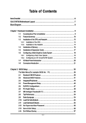
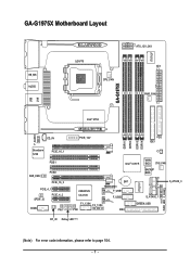
GA-G1975X PWR_FAN IT8712F GA-G1975X Motherboard Layout KB_MS AUDIO LGA775 CPU_FAN ATX_12V_2X4 ATX PWR_FAN USB F_AUDIO LAN Intel® 975X CD_IN Broadcom 5789 PCIE_16_1 PCIE1 SUR_CEN PCIE2 PCIE_16_2 PCIE_4_1 SPDIF_IO PCIE_4_2 COMA PW1 PCIE_12V FDD IDE1 DDRII1 DDRII2 DDRII3 DDRII4 CI Intel® ICH7R MAIN BIOS SYS_FAN BACKUP BIOS CREATIVE CA0106 BAT TSB43AB23 F_USB1 F_USB2 F1_1394 F2_1394 PW2 IDE2 S_ATAII0_1 GREEN_USB IT8211F PWR_LED F_PANEL S_ATAII2_3 RF_ID Debug LED (Note) (Note) For error code information, please refer to page 104. - 7 -
GA-G1975X PWR_FAN IT8712F GA-G1975X Motherboard Layout KB_MS AUDIO LGA775 CPU_FAN ATX_12V_2X4 ATX PWR_FAN USB F_AUDIO LAN Intel® 975X CD_IN Broadcom 5789 PCIE_16_1 PCIE1 SUR_CEN PCIE2 PCIE_16_2 PCIE_4_1 SPDIF_IO PCIE_4_2 COMA PW1 PCIE_12V FDD IDE1 DDRII1 DDRII2 DDRII3 DDRII4 CI Intel® ICH7R MAIN BIOS SYS_FAN BACKUP BIOS CREATIVE CA0106 BAT TSB43AB23 F_USB1 F_USB2 F1_1394 F2_1394 PW2 IDE2 S_ATAII0_1 GREEN_USB IT8211F PWR_LED F_PANEL S_ATAII2_3 RF_ID Debug LED (Note) (Note) For error code information, please refer to page 104. - 7 -
Manual
Page 8
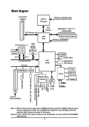
Go to 888MHz (must be overclocked to GIGABYTE's website for more information about the supported DDR II memory modules for this feature. (Note 2) To use a DDR II 667 memory module on the motherboard, you must install an 800/1066MHz FSB processor. - 8 - Block Diagram 2 PCI-ECLK (100MHz) LGA775 Processor CPUCLK+/-(266/200 MHz) PCI...
Go to 888MHz (must be overclocked to GIGABYTE's website for more information about the supported DDR II memory modules for this feature. (Note 2) To use a DDR II 667 memory module on the motherboard, you must install an 800/1066MHz FSB processor. - 8 - Block Diagram 2 PCI-ECLK (100MHz) LGA775 Processor CPUCLK+/-(266/200 MHz) PCI...
Manual
Page 9
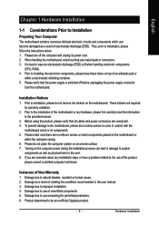
...violating the conditions recommended in contact with the motherboard circuit or its power cord. 2. Damage due to come in the user manual. 3. Turning on an uneven surface. 7. Thus, prior to the user. 8. Damage due to be an unofficial Gigabyte product. - 9 - Please do not ...allow screws to use exceeding the permitted parameters. 6. To prevent damage to the motherboard, please do not place the computer system on the computer power during the installation ...
...violating the conditions recommended in contact with the motherboard circuit or its power cord. 2. Damage due to come in the user manual. 3. Turning on an uneven surface. 7. Thus, prior to the user. 8. Damage due to be an unofficial Gigabyte product. - 9 - Please do not ...allow screws to use exceeding the permitted parameters. 6. To prevent damage to the motherboard, please do not place the computer system on the computer power during the installation ...

Manual
Page 10
... Š Supports 1.8V DDR II DIMMs Š Supports ECC/non-ECC type DRAM Š 2 PCI Express x 16 slot Š 2 PCI Express x 4 slots Š 2 PCI slots GA-G1975X Motherboard - 10 - Supports ATAPI mode for Serial ATA Š Onboard IT8211F chipset - 1 IDE connector (IDE2) (UDMA 33/ATA 66/ATA 100/ATA 133), suppport, allowing connection...
... Š Supports 1.8V DDR II DIMMs Š Supports ECC/non-ECC type DRAM Š 2 PCI Express x 16 slot Š 2 PCI Express x 4 slots Š 2 PCI slots GA-G1975X Motherboard - 10 - Supports ATAPI mode for Serial ATA Š Onboard IT8211F chipset - 1 IDE connector (IDE2) (UDMA 33/ATA 66/ATA 100/ATA 133), suppport, allowing connection...
Manual
Page 12
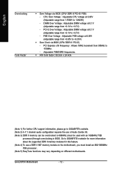
Go to GIGABYTE's website for more information about the supported DDR II memory modules for this feature. (Note 4) To use of Audio Combo Kit. (Note 3) DDR II memory can be overclocked to 1.0625V) - GA-G1975X Motherboard - 12 - FSB Over Voltage : Adjustable FSB voltage at ...0.1V (Adjustable range from 90MHz to +0.35V) Š Over Clock via BIOS (CPU/ DDR II/ PCI-E/ FSB) - Adjustable FSB/DDRII frequencies. Š ATX form factor; 30.5cm x 24.4cm (Note 1) For further CPU support information, please go to GIGABYTE...
Go to GIGABYTE's website for more information about the supported DDR II memory modules for this feature. (Note 4) To use of Audio Combo Kit. (Note 3) DDR II memory can be overclocked to 1.0625V) - GA-G1975X Motherboard - 12 - FSB Over Voltage : Adjustable FSB voltage at ...0.1V (Adjustable range from 90MHz to +0.35V) Š Over Clock via BIOS (CPU/ DDR II/ PCI-E/ FSB) - Adjustable FSB/DDRII frequencies. Š ATX form factor; 30.5cm x 24.4cm (Note 1) For further CPU support information, please go to GIGABYTE...
Manual
Page 13
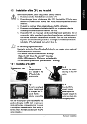
... - Please make sure that the system bus frequency be set the CPU host frequency in a straight and downwards motion. It is not recommended that the motherboard supports the CPU. 2. HT functionality requirement content : Enabling the functionality of Hyper-Threading Technology for your thumb and forefinger, carefully place it does not meet...
... - Please make sure that the system bus frequency be set the CPU host frequency in a straight and downwards motion. It is not recommended that the motherboard supports the CPU. 2. HT functionality requirement content : Enabling the functionality of Hyper-Threading Technology for your thumb and forefinger, carefully place it does not meet...

Manual
Page 14
...of the heatsink paste.To prevent such an occurrence, it is only for detailed installation instructions, please refer to the pin hole on the motherboard.Pressing down the push pins diagonally. Fig. 4 Please make sure the Male and Female push pin are joined closely. (for Intel boxed... heatsink may adhere to the CPU fan header located on the motherboard. English 1-3-2 Installation of the Heatsink Male Push Pin The top of Female Push Pin Female Push Pin Fig.1 Please apply an even layer of heatsink paste on the surface of motherboard after installing. GA-G1975X Motherboard - 14 -
...of the heatsink paste.To prevent such an occurrence, it is only for detailed installation instructions, please refer to the pin hole on the motherboard.Pressing down the push pins diagonally. Fig. 4 Please make sure the Male and Female push pin are joined closely. (for Intel boxed... heatsink may adhere to the CPU fan header located on the motherboard. English 1-3-2 Installation of the Heatsink Male Push Pin The top of Female Push Pin Female Push Pin Fig.1 Please apply an even layer of heatsink paste on the surface of motherboard after installing. GA-G1975X Motherboard - 14 -
Manual
Page 15
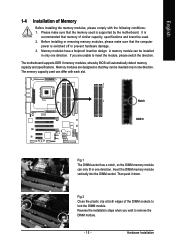
It is supported by the motherboard. The motherboard supports DDR II memory modules, whereby BIOS will automatically detect memory capacity and specifications. The memory capacity used can be installed in only one direction. ...
It is supported by the motherboard. The motherboard supports DDR II memory modules, whereby BIOS will automatically detect memory capacity and specifications. The memory capacity used can be installed in only one direction. ...
Manual
Page 16
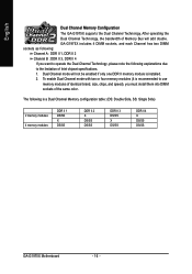
.... To enable Dual Channel mode with two or four memory modules (it is installed. 2. The following explanations due to the limitation of the same color. GA-G1975X includes 4 DIMM sockets, and each Channel has two DIMM sockets as following: Channel A : DDR II 1, DDR II 2 Channel B : DDR II 3, DDR II 4 If you want... modules DDR II 1 DS/SS X DS/SS DDR II 2 X DS/SS DS/SS DDR II 3 DS/SS X DS/SS DDR II 4 X DS/SS DS/SS GA-G1975X Motherboard - 16 - English Dual Channel Memory Configuration The GA-G1975X supports the Dual Channel Technology.
.... To enable Dual Channel mode with two or four memory modules (it is installed. 2. The following explanations due to the limitation of the same color. GA-G1975X includes 4 DIMM sockets, and each Channel has two DIMM sockets as following: Channel A : DDR II 1, DDR II 2 Channel B : DDR II 3, DDR II 4 If you want... modules DDR II 1 DS/SS X DS/SS DDR II 2 X DS/SS DS/SS DDR II 3 DS/SS X DS/SS DDR II 4 X DS/SS DS/SS GA-G1975X Motherboard - 16 - English Dual Channel Memory Configuration The GA-G1975X supports the Dual Channel Technology.
Manual
Page 17
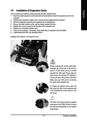
... below: 1. Replace the screw to secure the slot bracket of Expansion Cards You can also press the latch on the card are indeed seated in motherboard. 4. Install related driver from BIOS. 8. Make sure your computer's chassis cover, screws and slot bracket from the computer. 3. The PCIE_12V power connector supplies extra power...
... below: 1. Replace the screw to secure the slot bracket of Expansion Cards You can also press the latch on the card are indeed seated in motherboard. 4. Install related driver from BIOS. 8. Make sure your computer's chassis cover, screws and slot bracket from the computer. 3. The PCIE_12V power connector supplies extra power...
Manual
Page 18
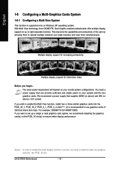
... and 25A (or above) +12V current. We recommend a power supply that can provide sufficient and stable power to your overall system configurations. GA-G1975X Motherboard - 18 - If you have to install at least one graphics card into the PCIE_16_1, PCIE_16_2, PCIE_4_1, PCIE_4_2 slots(Note). (It is ...the user by allowing them to spread multiple windows over eight monitors and view them simultaneously. For example: GIGABYTE GV-NX66T128D). With Multi View technology from GIGABYTE, Dual Graphic enabled motherboards offer multiple display support on Windows XP operating system.
... and 25A (or above) +12V current. We recommend a power supply that can provide sufficient and stable power to your overall system configurations. GA-G1975X Motherboard - 18 - If you have to install at least one graphics card into the PCIE_16_1, PCIE_16_2, PCIE_4_1, PCIE_4_2 slots(Note). (It is ...the user by allowing them to spread multiple windows over eight monitors and view them simultaneously. For example: GIGABYTE GV-NX66T128D). With Multi View technology from GIGABYTE, Dual Graphic enabled motherboards offer multiple display support on Windows XP operating system.
Manual
Page 19
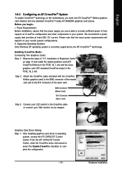
... of the master card and to complete the configuration. - 19 - Hardware Installation We recommend a power supply that the exact power requirements will depend on the motherboard, you begin-I Connector (Slave card) Step 3: Connect your LCD monitor to fully support an CrossFire configuration and other components in operating system, access the ATI...
... of the master card and to complete the configuration. - 19 - Hardware Installation We recommend a power supply that the exact power requirements will depend on the motherboard, you begin-I Connector (Slave card) Step 3: Connect your LCD monitor to fully support an CrossFire configuration and other components in operating system, access the ATI...


