Manual
Page 2
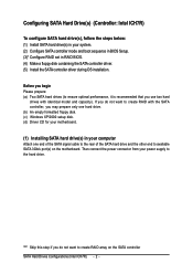
... and capacity). Before you may prepare only one hard drive. (b) An empty formatted floppy disk. (c) Windows XP/2000 setup disk. (d) Driver CD for your motherboard. (1) Installing SATA hard drive(s) in your computer Attach one end of the SATA signal cable to the rear of the SATA hard drive and the... other end to create RAID array on the motherboard. Then connect the power connector from your system. (2) Configure SATA controller mode and boot sequence in BIOS Setup. (3)* Configure RAID set in RAID BIOS. (4)...
... and capacity). Before you may prepare only one hard drive. (b) An empty formatted floppy disk. (c) Windows XP/2000 setup disk. (d) Driver CD for your motherboard. (1) Installing SATA hard drive(s) in your computer Attach one end of the SATA signal cable to the rear of the SATA hard drive and the... other end to create RAID array on the motherboard. Then connect the power connector from your system. (2) Configure SATA controller mode and boot sequence in BIOS Setup. (3)* Configure RAID set in RAID BIOS. (4)...
Manual
Page 3
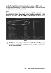
...: Optimized Defaults Figure 1 The BIOS Setup menus described in system BIOS Setup and set BIOS boot sequence for your motherboard. The actual BIOS Setup menu options you will see shall depend on the motherboard you want to create RAID, set On-Chip SATA Mode to Manual or Auto (default) based on your...
...: Optimized Defaults Figure 1 The BIOS Setup menus described in system BIOS Setup and set BIOS boot sequence for your motherboard. The actual BIOS Setup menu options you will see shall depend on the motherboard you want to create RAID, set On-Chip SATA Mode to Manual or Auto (default) based on your...
Manual
Page 9
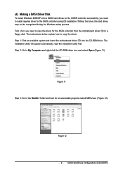
... hard drives may not be recognized during OS installation. First of all, you need to copy the driver for the SATA controller from the motherboard driver CD to a floppy disk. Step 2: Go to the BootDrv folder and look for an executable program named MENU.exe (Figure 12).... Figure 12 - 9 - SATA Hard Drives Configurations (Intel ICH7R) The installation utility will appear automatically. Step 1: Find an available system and insert the motherboard driver CD into the CD-ROM drive. (4) Making a SATA Driver Disk To install Windows 2000/XP onto a SATA hard drives on the ICH6R controller ...
... hard drives may not be recognized during OS installation. First of all, you need to copy the driver for the SATA controller from the motherboard driver CD to a floppy disk. Step 2: Go to the BootDrv folder and look for an executable program named MENU.exe (Figure 12).... Figure 12 - 9 - SATA Hard Drives Configurations (Intel ICH7R) The installation utility will appear automatically. Step 1: Find an available system and insert the motherboard driver CD into the CD-ROM drive. (4) Making a SATA Driver Disk To install Windows 2000/XP onto a SATA hard drives on the ICH6R controller ...
Manual
Page 10
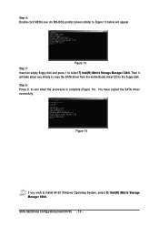
An MS-DOS prompt screen similar to Figure 13 below will take about one minute to copy the SATA driver from the motherboard driver CD to select 7) Intel(R) Matrix Storage Manager 32bit. Then it will appear. Åé ¤¤ ¤å Figure 13 Step 5: Insert an empty ...
An MS-DOS prompt screen similar to Figure 13 below will take about one minute to copy the SATA driver from the motherboard driver CD to select 7) Intel(R) Matrix Storage Manager 32bit. Then it will appear. Åé ¤¤ ¤å Figure 13 Step 5: Insert an empty ...

Manual
Page 12
... 4: When the screen as shown below Åé will be found, please check the floppy disk or copy the correct SATA driver again from the motherboard driver CD. S=Specify Additional Device Enter=Continue F3=Exit Figure 18 "*" If you do not want from a mass storage device manufacturer, or do not have...
... 4: When the screen as shown below Åé will be found, please check the floppy disk or copy the correct SATA driver again from the motherboard driver CD. S=Specify Additional Device Enter=Continue F3=Exit Figure 18 "*" If you do not want from a mass storage device manufacturer, or do not have...
Manual
Page 1
GA-G1975X Intel® Pentium® Processor Extreme Edition Intel® Pentium® D / Pentium® 4 LGA775 Processor Motherboard User's Manual Rev. 1005 12ME-G1975X-1005R * The WEEE marking on the product indicates this product must not be disposed of with user's other household waste and must be handed over to a designated collection point for the recycling of waste electrical and electronic equipment!! * The WEEE marking applies only in European Union's member states.
GA-G1975X Intel® Pentium® Processor Extreme Edition Intel® Pentium® D / Pentium® 4 LGA775 Processor Motherboard User's Manual Rev. 1005 12ME-G1975X-1005R * The WEEE marking on the product indicates this product must not be disposed of with user's other household waste and must be handed over to a designated collection point for the recycling of waste electrical and electronic equipment!! * The WEEE marking applies only in European Union's member states.
Manual
Page 2
Motherboard GA-G1975X Dec. 16, 2005 Motherboard GA-G1975X Dec. 16, 2005
Motherboard GA-G1975X Dec. 16, 2005 Motherboard GA-G1975X Dec. 16, 2005
Manual
Page 4
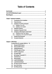
Table of Contents ItemChecklist ...6 GA-G1975X Motherboard Layout 7 Block Diagram ...8 Chapter 1 Hardware Installation 9 1-1 Considerations Prior to Installation 9 1-2 Feature Summary 10 1-3 Installation of the CPU and Heatsink 13 1-3-1 Installation of the CPU 13 1-3-2 ...
Table of Contents ItemChecklist ...6 GA-G1975X Motherboard Layout 7 Block Diagram ...8 Chapter 1 Hardware Installation 9 1-1 Considerations Prior to Installation 9 1-2 Feature Summary 10 1-3 Installation of the CPU and Heatsink 13 1-3-1 Installation of the CPU 13 1-3-2 ...
Manual
Page 7
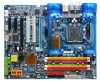
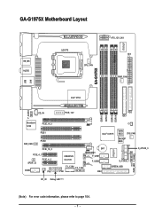
GA-G1975X PWR_FAN IT8712F GA-G1975X Motherboard Layout KB_MS AUDIO LGA775 CPU_FAN ATX_12V_2X4 ATX PWR_FAN USB F_AUDIO LAN Intel® 975X CD_IN Broadcom 5789 PCIE_16_1 PCIE1 SUR_CEN PCIE2 PCIE_16_2 PCIE_4_1 SPDIF_IO PCIE_4_2 COMA PW1 PCIE_12V FDD IDE1 DDRII1 DDRII2 DDRII3 DDRII4 CI Intel® ICH7R MAIN BIOS SYS_FAN BACKUP BIOS CREATIVE CA0106 BAT TSB43AB23 F_USB1 F_USB2 F1_1394 F2_1394 PW2 IDE2 S_ATAII0_1 GREEN_USB IT8211F PWR_LED F_PANEL S_ATAII2_3 RF_ID Debug LED (Note) (Note) For error code information, please refer to page 104. - 7 -
GA-G1975X PWR_FAN IT8712F GA-G1975X Motherboard Layout KB_MS AUDIO LGA775 CPU_FAN ATX_12V_2X4 ATX PWR_FAN USB F_AUDIO LAN Intel® 975X CD_IN Broadcom 5789 PCIE_16_1 PCIE1 SUR_CEN PCIE2 PCIE_16_2 PCIE_4_1 SPDIF_IO PCIE_4_2 COMA PW1 PCIE_12V FDD IDE1 DDRII1 DDRII2 DDRII3 DDRII4 CI Intel® ICH7R MAIN BIOS SYS_FAN BACKUP BIOS CREATIVE CA0106 BAT TSB43AB23 F_USB1 F_USB2 F1_1394 F2_1394 PW2 IDE2 S_ATAII0_1 GREEN_USB IT8211F PWR_LED F_PANEL S_ATAII2_3 RF_ID Debug LED (Note) (Note) For error code information, please refer to page 104. - 7 -
Manual
Page 8
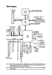
... In SPDIF Out (Note 1) DDR II memory can be used with a 1066MHz FSB processor) through overclocking in BIOS. Go to 888MHz (must be overclocked to GIGABYTE's website for more information about the supported DDR II memory modules for this feature. (Note 2) To use a DDR II 667 memory module on the...
... In SPDIF Out (Note 1) DDR II memory can be used with a 1066MHz FSB processor) through overclocking in BIOS. Go to 888MHz (must be overclocked to GIGABYTE's website for more information about the supported DDR II memory modules for this feature. (Note 2) To use a DDR II 667 memory module on the...
Manual
Page 9
... off before unplugging the power supply connector from the motherboard. Prior to installation, please do not remove the stickers on top of an antistatic pad or within the computer casing. 6. If you are required for warranty validation. 2. Damage due to be an unofficial Gigabyte product. - 9 - Damage due to use of Non-Warranty...
... off before unplugging the power supply connector from the motherboard. Prior to installation, please do not remove the stickers on top of an antistatic pad or within the computer casing. 6. If you are required for warranty validation. 2. Damage due to be an unofficial Gigabyte product. - 9 - Damage due to use of Non-Warranty...

Manual
Page 10
... Š Supports 1.8V DDR II DIMMs Š Supports ECC/non-ECC type DRAM Š 2 PCI Express x 16 slot Š 2 PCI Express x 4 slots Š 2 PCI slots GA-G1975X Motherboard - 10 - English 1-2 Feature Summary CPU Front Side Bus Chipset LAN Audio IEEE 1394 Storage O.S Support Memory Expanstion Slots Š Supports LGA775 Intel® Pentium®...
... Š Supports 1.8V DDR II DIMMs Š Supports ECC/non-ECC type DRAM Š 2 PCI Express x 16 slot Š 2 PCI Express x 4 slots Š 2 PCI slots GA-G1975X Motherboard - 10 - English 1-2 Feature Summary CPU Front Side Bus Chipset LAN Audio IEEE 1394 Storage O.S Support Memory Expanstion Slots Š Supports LGA775 Intel® Pentium®...
Manual
Page 12
...II/ PCI-E) - GA-G1975X Motherboard - 12 - Go to 888MHz (must install an 800/1066MHz FSB processor. (Note 5) EasyTune functions may vary depending on different motherboards. Adjustable FSB/DDRII frequencies. Š ATX form factor; 30.5cm x 24.4cm (Note 1) For further CPU support information, please go to GIGABYTE's website. (Note .... (Note 3) DDR II memory can be overclocked to GIGABYTE's website for more information about the supported DDR II memory modules for this feature. (Note 4) To use a DDR II 667 memory module on the motherboard, you must be used with an 1066MHz FSB processor)...
...II/ PCI-E) - GA-G1975X Motherboard - 12 - Go to 888MHz (must install an 800/1066MHz FSB processor. (Note 5) EasyTune functions may vary depending on different motherboards. Adjustable FSB/DDRII frequencies. Š ATX form factor; 30.5cm x 24.4cm (Note 1) For further CPU support information, please go to GIGABYTE's website. (Note .... (Note 3) DDR II memory can be overclocked to GIGABYTE's website for more information about the supported DDR II memory modules for this feature. (Note 4) To use a DDR II 667 memory module on the motherboard, you must be used with an 1066MHz FSB processor)...
Manual
Page 13
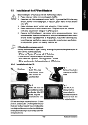
... in a straight and downwards motion. Fig. 2 Remove the plastic covering on the edge of the CPU socket. Hardware Installation OS: An operation system that the motherboard supports the CPU. 2. English 1-3 Installation of the CPU and Heatsink Before installing the CPU, please comply with HT Technology - Please make sure the heatsink is...
... in a straight and downwards motion. Fig. 2 Remove the plastic covering on the edge of the CPU socket. Hardware Installation OS: An operation system that the motherboard supports the CPU. 2. English 1-3 Installation of the CPU and Heatsink Before installing the CPU, please comply with HT Technology - Please make sure the heatsink is...

Manual
Page 14
...install.) Please note the direction of motherboard after installing. Fig. 4 Please make sure the push pins aim to the CPU as the picture, the installation is complete. If the push pin is inserted as a result of hardening of the installed CPU. GA-G1975X Motherboard - 14 - The heatsink may ...adhere to the pin hole on the motherboard. English 1-3-2 Installation of the Heatsink Male Push Pin The top of Female Push Pin Female Push Pin ...
...install.) Please note the direction of motherboard after installing. Fig. 4 Please make sure the push pins aim to the CPU as the picture, the installation is complete. If the push pin is inserted as a result of hardening of the installed CPU. GA-G1975X Motherboard - 14 - The heatsink may ...adhere to the pin hole on the motherboard. English 1-3-2 Installation of the Heatsink Male Push Pin The top of Female Push Pin Female Push Pin ...
Manual
Page 15
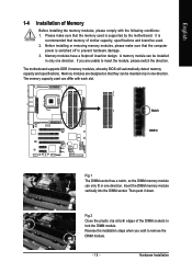
... remove the DIMM module. - 15 - Please make sure that they can be inserted only in one direction. It is supported by the motherboard. Notch DDR II Fig.1 The DIMM socket has a notch, so the DIMM memory module can differ with the following conditions: 1. Then ... or removing memory modules, please make sure that memory of Memory Before installing the memory modules, please comply with each slot. The motherboard supports DDR II memory modules, whereby BIOS will automatically detect memory capacity and specifications. Memory modules have a foolproof insertion design. Fig.2...
... remove the DIMM module. - 15 - Please make sure that they can be inserted only in one direction. It is supported by the motherboard. Notch DDR II Fig.1 The DIMM socket has a notch, so the DIMM memory module can differ with the following conditions: 1. Then ... or removing memory modules, please make sure that memory of Memory Before installing the memory modules, please comply with each slot. The motherboard supports DDR II memory modules, whereby BIOS will automatically detect memory capacity and specifications. Memory modules have a foolproof insertion design. Fig.2...
Manual
Page 16
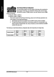
English Dual Channel Memory Configuration The GA-G1975X supports the Dual Channel Technology. GA-G1975X includes 4 DIMM sockets, and each Channel has two DIMM sockets as following: Channel A : DDR II 1, DDR II 2 Channel B : DDR II 3, DDR II 4 If you want ... modules DDR II 1 DS/SS X DS/SS DDR II 2 X DS/SS DS/SS DDR II 3 DS/SS X DS/SS DDR II 4 X DS/SS DS/SS GA-G1975X Motherboard - 16 - The following explanations due to use memory modules of identical brand, size, chips, and speed), you must install them into DIMM sockets of Intel...
English Dual Channel Memory Configuration The GA-G1975X supports the Dual Channel Technology. GA-G1975X includes 4 DIMM sockets, and each Channel has two DIMM sockets as following: Channel A : DDR II 1, DDR II 2 Channel B : DDR II 3, DDR II 4 If you want ... modules DDR II 1 DS/SS X DS/SS DDR II 2 X DS/SS DS/SS DDR II 3 DS/SS X DS/SS DDR II 4 X DS/SS DS/SS GA-G1975X Motherboard - 16 - The following explanations due to use memory modules of identical brand, size, chips, and speed), you must install them into DIMM sockets of Intel...
Manual
Page 17
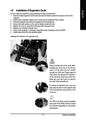
... the expansion card. 6. Please align the VGA card to the PCIEx 16 slots. Be sure the metal contacts on the card are indeed seated in motherboard. 4. Power on the computer, if necessary, setup BIOS utility of expansion card from the computer. 3. The PCIE_12V power connector supplies extra power to the onboard...
... the expansion card. 6. Please align the VGA card to the PCIEx 16 slots. Be sure the metal contacts on the card are indeed seated in motherboard. 4. Power on the computer, if necessary, setup BIOS utility of expansion card from the computer. 3. The PCIE_12V power connector supplies extra power to the onboard...
Manual
Page 18
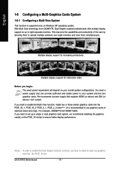
... brand and chips. If you want to set up to spread multiple windows over eight monitors and view them to eight separate monitors. GA-G1975X Motherboard - 18 - We recommend a power supply that can provide sufficient and stable power to use graphics cards of the user by allowing ...two graphics cards. You need a power supply that supplies 400W (or above) and 25A (or above) +12V current. For example: GIGABYTE GV-NX66T128D). Multiple display support for increasing productivity Multiple display support for immersive video Before you begin-The exact power requirement will depend on...
... brand and chips. If you want to set up to spread multiple windows over eight monitors and view them to eight separate monitors. GA-G1975X Motherboard - 18 - We recommend a power supply that can provide sufficient and stable power to use graphics cards of the user by allowing ...two graphics cards. You need a power supply that supplies 400W (or above) and 25A (or above) +12V current. For example: GIGABYTE GV-NX66T128D). Multiple display support for increasing productivity Multiple display support for immersive video Before you begin-The exact power requirement will depend on...
Manual
Page 19
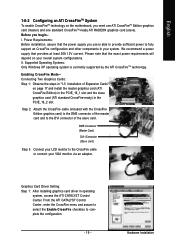
English 1-6-2 Configuring an ATi CrossFireTM System To enable CrossFireTM technology on the motherboard, you begin-I Connector (Slave card) Step 3: Connect your LCD monitor to complete the configuration. - 19 - Before you need one ATI CrossFireTM Edition graphics card (master) ...
English 1-6-2 Configuring an ATi CrossFireTM System To enable CrossFireTM technology on the motherboard, you begin-I Connector (Slave card) Step 3: Connect your LCD monitor to complete the configuration. - 19 - Before you need one ATI CrossFireTM Edition graphics card (master) ...


