
Manual
Page 1
GA-EX38-DQ6 LGA775 socket motherboard for Intel® CoreTM processor family/ Intel® Pentium® processor family/Intel® Celeron® processor family User's Manual Rev. 1101 12ME-EX38DQ6-1101R
GA-EX38-DQ6 LGA775 socket motherboard for Intel® CoreTM processor family/ Intel® Pentium® processor family/Intel® Celeron® processor family User's Manual Rev. 1101 12ME-EX38DQ6-1101R

Manual
Page 2
Motherboard GA-EX38-DQ6 Feb. 22, 2008 Motherboard GA-EX38-DQ6 Feb. 22, 2008
Motherboard GA-EX38-DQ6 Feb. 22, 2008 Motherboard GA-EX38-DQ6 Feb. 22, 2008

Manual
Page 3
...looking for technical information. For product-related information, check on our website at: http://www.gigabyte.com.tw Identifying Your Motherboard Revision The revision number on our website. GIGABYTE UNITED INC. The logo is 1.0. For example, "REV: 1.0" means the revision of ... this manual is protected by copyright laws and is designated by GIGABYTE without GIGABYTE's prior written permission. All rights reserved. is the property of GIGABYTE branded motherboards. sive global distributor of GIGABYTE. Example: Disclaimer Information in this manual may be made by GIGA...
...looking for technical information. For product-related information, check on our website at: http://www.gigabyte.com.tw Identifying Your Motherboard Revision The revision number on our website. GIGABYTE UNITED INC. The logo is 1.0. For example, "REV: 1.0" means the revision of ... this manual is protected by copyright laws and is designated by GIGABYTE without GIGABYTE's prior written permission. All rights reserved. is the property of GIGABYTE branded motherboards. sive global distributor of GIGABYTE. Example: Disclaimer Information in this manual may be made by GIGA...

Manual
Page 4
Table of Contents Box Contents ...6 OptionalItems...6 GA-EX38-DQ6 Motherboard Layout 7 Block Diagram...8 Chapter 1 Hardware Installation 9 1-1 Installation Precautions 9 1-2 Product Specifications 10 1-3 Installing the CPU and CPU Cooler 13 1-3-1 Installing the CPU 13 1-3-2 Installing the CPU Cooler 15 1-3-3 Removing the Crazy Cool Heatsink from the Back of the Motherboard ..... 16 1-4 Installing the Memory 17 1-4-1 Dual Channel Memory...
Table of Contents Box Contents ...6 OptionalItems...6 GA-EX38-DQ6 Motherboard Layout 7 Block Diagram...8 Chapter 1 Hardware Installation 9 1-1 Installation Precautions 9 1-2 Product Specifications 10 1-3 Installing the CPU and CPU Cooler 13 1-3-1 Installing the CPU 13 1-3-2 Installing the CPU Cooler 15 1-3-3 Removing the Crazy Cool Heatsink from the Back of the Motherboard ..... 16 1-4 Installing the Memory 17 1-4-1 Dual Channel Memory...

Manual
Page 6
Box Contents GA-EX38-DQ6 motherboard Motherboard driver disk User's Manual Quick Installation Guide Intel® LGA775 CPU Installation Guide One IDE cable and one floppy disk drive cable Four SATA 3Gb/s cables Two SATA brackets I/O Shield Two screws • The box contents above are subject to change without notice. • The motherboard image is for reference...
Box Contents GA-EX38-DQ6 motherboard Motherboard driver disk User's Manual Quick Installation Guide Intel® LGA775 CPU Installation Guide One IDE cable and one floppy disk drive cable Four SATA 3Gb/s cables Two SATA brackets I/O Shield Two screws • The box contents above are subject to change without notice. • The motherboard image is for reference...

Manual
Page 7
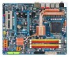
GA-EX38-DQ6 Motherboard Layout KB_MS RCA_SPDIF USB_1394_1 SYS_FAN1 ATX_12V_2X LGA775 CPU_FAN V_PHASE LED ATX USB_1394_2 USB_LAN1 USB_LAN2 RTL8111B/ RTL8111C AUDIO F_AUDIO PCIE_1 NB_FAN RTL8111B/ RTL8111C CODEC CD_IN PCIE_16_1 PCIE_2 PCIE_3 BP_BIOS MAIN_BIOS PCIE_16_2 Intel® X38 GA-EX38-DQ6 BAT CLR_CMOS Intel® ICH9R DDRII1 DDRII2 DDRII3 DDRII4 PWR_FAN FDD SATAII0 IDE SATAII1 SPDIF_O PCI1 IT8718 PCI2 LPT CI COM TPM F_1394 F_USB2 F_USB1 TSB43AB23 GIGABYTE SATA2 SATAII4 SATAII2 GSATAIIA PWR_LED SPDIF_IN SYS_FAN2 F_PANEL SATAII5 SATAII3 GSATAIIB - 7 -
GA-EX38-DQ6 Motherboard Layout KB_MS RCA_SPDIF USB_1394_1 SYS_FAN1 ATX_12V_2X LGA775 CPU_FAN V_PHASE LED ATX USB_1394_2 USB_LAN1 USB_LAN2 RTL8111B/ RTL8111C AUDIO F_AUDIO PCIE_1 NB_FAN RTL8111B/ RTL8111C CODEC CD_IN PCIE_16_1 PCIE_2 PCIE_3 BP_BIOS MAIN_BIOS PCIE_16_2 Intel® X38 GA-EX38-DQ6 BAT CLR_CMOS Intel® ICH9R DDRII1 DDRII2 DDRII3 DDRII4 PWR_FAN FDD SATAII0 IDE SATAII1 SPDIF_O PCI1 IT8718 PCI2 LPT CI COM TPM F_1394 F_USB2 F_USB1 TSB43AB23 GIGABYTE SATA2 SATAII4 SATAII2 GSATAIIA PWR_LED SPDIF_IN SYS_FAN2 F_PANEL SATAII5 SATAII3 GSATAIIB - 7 -

Manual
Page 9
...come in a high-temperature environment. • Turning on the power, make sure they are connected tightly and securely. • When handling the motherboard, avoid touching any installation steps or have it on top of an antistatic pad or within the computer casing. • Do not place the ...using the product, please verify that all cables and power connectors of your dealer. These stickers are connected. • To prevent damage to the motherboard, do not have an ESD wrist strap, keep your hands dry and first touch a metal object to eliminate static electricity. • Prior to...
...come in a high-temperature environment. • Turning on the power, make sure they are connected tightly and securely. • When handling the motherboard, avoid touching any installation steps or have it on top of an antistatic pad or within the computer casing. • Do not place the ...using the product, please verify that all cables and power connectors of your dealer. These stickers are connected. • To prevent damage to the motherboard, do not have an ESD wrist strap, keep your hands dry and first touch a metal object to eliminate static electricity. • Prior to...

Manual
Page 10
... RAID 0, RAID 1, RAID 5, and RAID 10 Š GIGABYTE SATA2 chip: - 1 x IDE connector supporting ATA-133/100/66/33 and up to 2 IDE devices - 2 x SATA 3Gb/s connectors (GSATAIIA, GSATAIIB) supporting up to the internal IEEE 1394a header) GA-EX38-DQ6 Motherboard - 10 - Support for SATA RAID 0, RAID 1, and JBOD...of system memory (Note 1) Š Dual channel memory architecture Š Support for DDR2 1200/1066/800/667 MHz memory modules (Go to GIGABYTE's website for the latest memory support list.) Š Support for ECC memory Š Realtek ALC889A codec Š High Definition Audio Š ...
... RAID 0, RAID 1, RAID 5, and RAID 10 Š GIGABYTE SATA2 chip: - 1 x IDE connector supporting ATA-133/100/66/33 and up to 2 IDE devices - 2 x SATA 3Gb/s connectors (GSATAIIA, GSATAIIB) supporting up to the internal IEEE 1394a header) GA-EX38-DQ6 Motherboard - 10 - Support for SATA RAID 0, RAID 1, and JBOD...of system memory (Note 1) Š Dual channel memory architecture Š Support for DDR2 1200/1066/800/667 MHz memory modules (Go to GIGABYTE's website for the latest memory support list.) Š Support for ECC memory Š Realtek ALC889A codec Š High Definition Audio Š ...

Manual
Page 12
...4 GB. (Note 2) Whether the CPU fan speed control function is supported will depend on the CPU being used. (Note 5) Due to : - GA-EX38-DQ6 Motherboard - 12 - Adjust PCI Express frequency from 100 MHz to 700 MHz with 0.05V increment - Increase DDR2 voltage by 0.05V to 1.55V with 1 ...(CPU/DDR2/PCIe) allow you to chipset limitation, Intel ICH9R RAID driver does not support Windows 2000 operating system. Increase PCIe voltage by motherboard model. (Note 4) The adjustable CPU voltage range depends on the CPU cooler you install. (Note 3) Available functions in Easytune may differ...
...4 GB. (Note 2) Whether the CPU fan speed control function is supported will depend on the CPU being used. (Note 5) Due to : - GA-EX38-DQ6 Motherboard - 12 - Adjust PCI Express frequency from 100 MHz to 700 MHz with 0.05V increment - Increase DDR2 voltage by 0.05V to 1.55V with 1 ...(CPU/DDR2/PCIe) allow you to chipset limitation, Intel ICH9R RAID driver does not support Windows 2000 operating system. Increase PCIe voltage by motherboard model. (Note 4) The adjustable CPU voltage range depends on the CPU cooler you install. (Note 3) Available functions in Easytune may differ...

Manual
Page 13
... the CPU. (Go to GIGABYTE's website for the peripherals. 1-3 Installing the CPU and CPU Cooler Read the following guidelines before installing the CPU to your hardware specifications including the CPU, graphics card, memory, hard drive, etc. 1-3-1 Installing the CPU A. Hardware Installation Locate the alignment keys on the motherboard CPU socket and the...
... the CPU. (Go to GIGABYTE's website for the peripherals. 1-3 Installing the CPU and CPU Cooler Read the following guidelines before installing the CPU to your hardware specifications including the CPU, graphics card, memory, hard drive, etc. 1-3-1 Installing the CPU A. Hardware Installation Locate the alignment keys on the motherboard CPU socket and the...

Manual
Page 14
GA-EX38-DQ6 Motherboard - 14 - Follow the steps below to the CPU. Step 2: Remove the protective socket cover. Align the CPU pin one marking (triangle) with the pin one ... prevent damage to correctly install the CPU into position. Step 4: Hold the CPU with the socket alignment keys) and gently insert the CPU into the motherboard CPU socket. Step 3: Lift the metal load plate on the CPU socket. CPU Socket Lever Step 1: Completely raise the CPU socket lever. B.
GA-EX38-DQ6 Motherboard - 14 - Follow the steps below to the CPU. Step 2: Remove the protective socket cover. Align the CPU pin one marking (triangle) with the pin one ... prevent damage to correctly install the CPU into position. Step 4: Hold the CPU with the socket alignment keys) and gently insert the CPU into the motherboard CPU socket. Step 3: Lift the metal load plate on the CPU socket. CPU Socket Lever Step 1: Completely raise the CPU socket lever. B.

Manual
Page 15
... of the CPU cooler to install.) Step 3: Place the cooler atop the CPU, aligning the four push pins through the pin holes on the motherboard. Direction of the Arrow Sign on the Male Push Pin Male Push Pin The Top of Female Push Pin Female Push Pin Step 2: Before installing... Follow the steps below to your CPU cooler installation manual for instructions on installing the cooler.) Step 5: After the installation, check the back of the motherboard. Push down each push pin. Step 4: You should hear a "click" when pushing down on the push pins diagonally. Use extreme care when removing the ...
... of the CPU cooler to install.) Step 3: Place the cooler atop the CPU, aligning the four push pins through the pin holes on the motherboard. Direction of the Arrow Sign on the Male Push Pin Male Push Pin The Top of Female Push Pin Female Push Pin Step 2: Before installing... Follow the steps below to your CPU cooler installation manual for instructions on installing the cooler.) Step 5: After the installation, check the back of the motherboard. Push down each push pin. Step 4: You should hear a "click" when pushing down on the push pins diagonally. Use extreme care when removing the ...

Manual
Page 16
...the heatsink mounting holes, insert one of the screws provided with the motherboard Step 1: Use a Philips screwdriver to unfasten the three screws as shown and remove the spring nuts. A Philips screwdriver 2. GA-EX38-DQ6 Motherboard - 16 - Step 2: Unfasten the two spring nuts on the... North Bridge heatsink as shown in appearance from the back of the motherboard. 1. Step 5: Do the same for damage of motherboard function(s) or component(s) resulting from the ...
...the heatsink mounting holes, insert one of the screws provided with the motherboard Step 1: Use a Philips screwdriver to unfasten the three screws as shown and remove the spring nuts. A Philips screwdriver 2. GA-EX38-DQ6 Motherboard - 16 - Step 2: Unfasten the two spring nuts on the... North Bridge heatsink as shown in appearance from the back of the motherboard. 1. Step 5: Do the same for damage of motherboard function(s) or component(s) resulting from the ...

Manual
Page 17
... the Memory Read the following guidelines before you are unable to insert the memory, switch the direction. 1-4-1 Dual Channel Memory Configuration This motherboard provides four DDR2 memory sockets and supports Dual Channel Technology. A memory module can be enabled if only one direction. If you begin ...DS/SS DDRII4 - DS/SS DS/SS (SS=Single-Sided, DS=Double-Sided, "- -"=No Memory) DDRII1 DDRII2 DDRII3 DDRII4 Due to GIGABYTE's website for optimum performance. Intel® Flex Memory Technology offers greater flexibility to upgrade by allowing different memory sizes to be used . ...
... the Memory Read the following guidelines before you are unable to insert the memory, switch the direction. 1-4-1 Dual Channel Memory Configuration This motherboard provides four DDR2 memory sockets and supports Dual Channel Technology. A memory module can be enabled if only one direction. If you begin ...DS/SS DDRII4 - DS/SS DS/SS (SS=Single-Sided, DS=Double-Sided, "- -"=No Memory) DDRII1 DDRII2 DDRII3 DDRII4 Due to GIGABYTE's website for optimum performance. Intel® Flex Memory Technology offers greater flexibility to upgrade by allowing different memory sizes to be used . ...

Manual
Page 18
... steps below to correctly install your memory modules in the picture on the left, place your fingers on the top edge of the memory socket. GA-EX38-DQ6 Motherboard - 18 - Place the memory module on the socket. Step 2: The clips at both ends of the memory module. Spread the retaining clips at both ends... , make sure to turn off the computer and unplug the power cord from the power outlet to prevent damage to install DDR2 DIMMs on this motherboard. DDR2 DIMMs are not compatible to DDR DIMMs. Be sure to the memory module.
... steps below to correctly install your memory modules in the picture on the left, place your fingers on the top edge of the memory socket. GA-EX38-DQ6 Motherboard - 18 - Place the memory module on the socket. Step 2: The clips at both ends of the memory module. Spread the retaining clips at both ends... , make sure to turn off the computer and unplug the power cord from the power outlet to prevent damage to install DDR2 DIMMs on this motherboard. DDR2 DIMMs are not compatible to DDR DIMMs. Be sure to the memory module.

Manual
Page 19
... the slot. 4. Make sure the metal contacts on your computer. If necessary, go to BIOS Setup to install an expansion card: • Make sure the motherboard supports the expansion card. Hardware Installation PCI Express x16 Slot PCI Express x1 Slot PCI Slot Follow the steps below to the chassis back panel...
... the slot. 4. Make sure the metal contacts on your computer. If necessary, go to BIOS Setup to install an expansion card: • Make sure the motherboard supports the expansion card. Hardware Installation PCI Express x16 Slot PCI Express x1 Slot PCI Slot Follow the steps below to the chassis back panel...

Manual
Page 20
Then attach the SATA power cable to the power connector on the bracket. GA-EX38-DQ6 Motherboard - 20 - For SATA device in external enclosure, you to connect external SATA device(s) to your system by expanding the internal SATA port(s) to the chassis ...back panel. • Turn off the power of the SATA signal cable and SATA power cable to your motherboard. the external SATA con- Connect the other ends of the external enclosure. Follow the steps below to install the SATA bracket: Step 1: Locate one end...
Then attach the SATA power cable to the power connector on the bracket. GA-EX38-DQ6 Motherboard - 20 - For SATA device in external enclosure, you to connect external SATA device(s) to your system by expanding the internal SATA port(s) to the chassis ...back panel. • Turn off the power of the SATA signal cable and SATA power cable to your motherboard. the external SATA con- Connect the other ends of the external enclosure. Follow the steps below to install the SATA bracket: Step 1: Locate one end...

Manual
Page 21
... may be interchanged based on the hardware design. - 21 - Use this port for an IEEE 1394a device. Do not rock it straight out from the motherboard. • When removing the cable, pull it side to side to an external audio system that your device and then remove it from the connector...
... may be interchanged based on the hardware design. - 21 - Use this port for an IEEE 1394a device. Do not rock it straight out from the motherboard. • When removing the cable, pull it side to side to an external audio system that your device and then remove it from the connector...

Manual
Page 22
.... Microphones must be connected to the instructions on setting up a 2/4/5.1/ 7.1-channel audio configuration in jack ( ). Refer to the default Mic in Chapter 5, "Configuring 2/4/5.1/7.1-Channel Audio." GA-EX38-DQ6 Motherboard - 22 - Only microphones still MUST be connected to connect front speakers in a 4/5.1/7.1-channel audio configuration. Use this jack. This jack can be used to this...
.... Microphones must be connected to the instructions on setting up a 2/4/5.1/ 7.1-channel audio configuration in jack ( ). Refer to the default Mic in Chapter 5, "Configuring 2/4/5.1/7.1-Channel Audio." GA-EX38-DQ6 Motherboard - 22 - Only microphones still MUST be connected to connect front speakers in a 4/5.1/7.1-channel audio configuration. Use this jack. This jack can be used to this...

Manual
Page 23
...) F_USB1/F_USB2 19) F_1394 20) LPT 21) TPM 22) COM 23) CI 24) CLR_CMOS 25) V_PHASE LED Read the following guidelines before turning on the motherboard. - 23 -
...) F_USB1/F_USB2 19) F_1394 20) LPT 21) TPM 22) COM 23) CI 24) CLR_CMOS 25) V_PHASE LED Read the following guidelines before turning on the motherboard. - 23 -


