
Manual
Page 4
...Heatsink from the Back of the Motherboard ..... 16 1-4 Installing the Memory 17 1-4-1 Dual Channel Memory Configuration 17 1-4-2 Installing a Memory 18 1-5 Installing an Expansion Card 19 1-6 Installing the SATA Bracket 20 1-7 Back Panel Connectors 21 1-8 Internal Connectors 23 Chapter 2 BIOS Setup 37 2-1 Startup Screen 38 2-2 The Main Menu 39 2-3 Standard CMOS Features 41 2-4 Advanced BIOS Features 43 2-5 IntegratedPeripherals 45 2-6 Power Management Setup 49 2-7 PnP/PCI Configurations 51 2-8 PC Health Status 52 2-9 MB Intelligent Tweaker(M.I.T 54 2-10 Load Fail-Safe Defaults...
...Heatsink from the Back of the Motherboard ..... 16 1-4 Installing the Memory 17 1-4-1 Dual Channel Memory Configuration 17 1-4-2 Installing a Memory 18 1-5 Installing an Expansion Card 19 1-6 Installing the SATA Bracket 20 1-7 Back Panel Connectors 21 1-8 Internal Connectors 23 Chapter 2 BIOS Setup 37 2-1 Startup Screen 38 2-2 The Main Menu 39 2-3 Standard CMOS Features 41 2-4 Advanced BIOS Features 43 2-5 IntegratedPeripherals 45 2-6 Power Management Setup 49 2-7 PnP/PCI Configurations 51 2-8 PC Health Status 52 2-9 MB Intelligent Tweaker(M.I.T 54 2-10 Load Fail-Safe Defaults...

Manual
Page 10
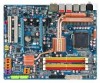
...; 2 x PCI slots Š South Bridge: - 6 x SATA 3Gb/s connectors (SATAII0, SATAII1, SATAII2, SATAII3, SATAII4, SATAII5) supporting up to 1 floppy disk drive Š T.I. TSB43AB23 chip Š Up to 3 IEEE 1394a ports (2 on the back panel, 1 via the IEEE 1394a bracket connected to 2 SATA 3Gb/s devices - Support for SATA RAID 0, RAID 1, RAID 5, and RAID 10 Š GIGABYTE SATA2 chip: - 1 x IDE connector supporting ATA-133/100/66/33 and up to 2 IDE devices - 2 x SATA 3Gb/s connectors (GSATAIIA, GSATAIIB) supporting up to the internal IEEE 1394a header) GA-EX38-DQ6 Motherboard...
...; 2 x PCI slots Š South Bridge: - 6 x SATA 3Gb/s connectors (SATAII0, SATAII1, SATAII2, SATAII3, SATAII4, SATAII5) supporting up to 1 floppy disk drive Š T.I. TSB43AB23 chip Š Up to 3 IEEE 1394a ports (2 on the back panel, 1 via the IEEE 1394a bracket connected to 2 SATA 3Gb/s devices - Support for SATA RAID 0, RAID 1, RAID 5, and RAID 10 Š GIGABYTE SATA2 chip: - 1 x IDE connector supporting ATA-133/100/66/33 and up to 2 IDE devices - 2 x SATA 3Gb/s connectors (GSATAIIA, GSATAIIB) supporting up to the internal IEEE 1394a header) GA-EX38-DQ6 Motherboard...

Manual
Page 12
... (OEM version) Š Voltage adjustments in BIOS Setup (CPU/DDR2/PCIe) allow you to 0.75V with 1 MHz increment - Adjust PCI Express frequency from 100 MHz to 700 MHz with 0.05V increment - GA-EX38-DQ6 Motherboard - 12 - BIOS Unique Features Bundled Software Overclocking Operating System Form Factor Š 2 x 8 Mbit flash Š Use of physical memory is installed, the actual memory size displayed will be less than 4 GB. (Note 2) Whether the CPU fan speed control function is supported will depend...
... (OEM version) Š Voltage adjustments in BIOS Setup (CPU/DDR2/PCIe) allow you to 0.75V with 1 MHz increment - Adjust PCI Express frequency from 100 MHz to 700 MHz with 0.05V increment - GA-EX38-DQ6 Motherboard - 12 - BIOS Unique Features Bundled Software Overclocking Operating System Form Factor Š 2 x 8 Mbit flash Š Use of physical memory is installed, the actual memory size displayed will be less than 4 GB. (Note 2) Whether the CPU fan speed control function is supported will depend...

Manual
Page 25
... power connector wires. Do not place a jumper cap on the headers. - 25 - 3/4/5) CPU_FAN/SYS_FAN1/SYS_FAN2/PWR_FAN (Fan Headers) The motherboard has a 4-pin CPU fan header (CPU_FAN), a 3-pin (SYS_FAN1) and a 4-pin (SYS_FAN2) system fan headers, and a 3-pin power fan header (PWR_FAN). When connecting a fan cable, be installed inside the chassis. 1 CPU_FAN CPU_FAN: Pin No. 1 2 3 4 Definition GND +12V / Speed Control Sense Speed Control 1 SYS_FAN2 SYS_FAN2: Pin No. 1 2 3 4 Definition GND Speed Control Sense +5V SYS_FAN1/PWR_FAN: Pin No. Each fan header supplies a +12V power voltage...
... power connector wires. Do not place a jumper cap on the headers. - 25 - 3/4/5) CPU_FAN/SYS_FAN1/SYS_FAN2/PWR_FAN (Fan Headers) The motherboard has a 4-pin CPU fan header (CPU_FAN), a 3-pin (SYS_FAN1) and a 4-pin (SYS_FAN2) system fan headers, and a 3-pin power fan header (PWR_FAN). When connecting a fan cable, be installed inside the chassis. 1 CPU_FAN CPU_FAN: Pin No. 1 2 3 4 Definition GND +12V / Speed Control Sense Speed Control 1 SYS_FAN2 SYS_FAN2: Pin No. 1 2 3 4 Definition GND Speed Control Sense +5V SYS_FAN1/PWR_FAN: Pin No. Each fan header supplies a +12V power voltage...

Manual
Page 35
... lighted LEDs indicates the CPU loading. Open: Normal Short: Clear CMOS Values • Always turn off your computer, be sure to touch the two pins for BIOS configurations). 25) V_PHASE LED The number of lighted LEDs. - 35 - Failure to do so may cause damage to the motherboard. • After system restart, go to BIOS Setup to load factory defaults (select Load Optimized Defaults) or manually configure the BIOS settings (refer to factory defaults. date information and BIOS configurations) and reset...
... lighted LEDs indicates the CPU loading. Open: Normal Short: Clear CMOS Values • Always turn off your computer, be sure to touch the two pins for BIOS configurations). 25) V_PHASE LED The number of lighted LEDs. - 35 - Failure to do so may cause damage to the motherboard. • After system restart, go to BIOS Setup to load factory defaults (select Load Optimized Defaults) or manually configure the BIOS settings (refer to factory defaults. date information and BIOS configurations) and reset...

Manual
Page 43
... or down on the list. HDD S.M.A.R.T. Options are: Floppy, LS120, Hard Disk, CDROM, ZIP, USB-FDD, USB-ZIP, USB-CDROM, USB-HDD, Legacy LAN, Disabled. Setup System A password is only required for entering the BIOS Setup program. Press to report read/write errors of loading the operating system from the available devices. This feature allows your hard drive. Capability Limit CPUID Max. After configuring this item, set the password(s) under the Set Supervisor/User Password item in the BIOS Main Menu. For more information...
... or down on the list. HDD S.M.A.R.T. Options are: Floppy, LS120, Hard Disk, CDROM, ZIP, USB-FDD, USB-ZIP, USB-CDROM, USB-HDD, Legacy LAN, Disabled. Setup System A password is only required for entering the BIOS Setup program. Press to report read/write errors of loading the operating system from the available devices. This feature allows your hard drive. Capability Limit CPUID Max. After configuring this item, set the password(s) under the Set Supervisor/User Password item in the BIOS Main Menu. For more information...

Manual
Page 44
...; CPU Enhanced Halt (C1E) function, a CPU power-saving function in independent partitions. Virtualization enhanced by Intel® Virtualization Technology will allow a platform to limit CPUID maximum value. PCI Sets the PCI graphics card as the first display. (Default) PEG Sets PCI Express graphics card on CPU loading, Intel® EIST technology can function as the first display. (Note) This item is overheated. (Default: Enabled) CPU EIST Function (Note) Enables or disables Enhanced Intel SpeedStep Technology (EIST). Limit CPUID Max. GA-EX38-DQ6 Motherboard...
...; CPU Enhanced Halt (C1E) function, a CPU power-saving function in independent partitions. Virtualization enhanced by Intel® Virtualization Technology will allow a platform to limit CPUID maximum value. PCI Sets the PCI graphics card as the first display. (Default) PEG Sets PCI Express graphics card on CPU loading, Intel® EIST technology can function as the first display. (Note) This item is overheated. (Default: Enabled) CPU EIST Function (Note) Enables or disables Enhanced Intel SpeedStep Technology (EIST). Limit CPUID Max. GA-EX38-DQ6 Motherboard...
Manual
Page 45
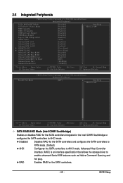
... hot plug. 2-5 Integrated Peripherals CMOS Setup Utility-Copyright (C) 1984-2008 Award Software Integrated Peripherals SATA RAID/AHCI Mode SATA Port0-3 Native Mode USB Controller USB 2.0 Controller USB Keyboard Support USB Mouse Support Legacy USB storage detect Azalia Codec Onboard H/W 1394 Onboard H/W LAN1 Onboard H/W LAN2 ` SMART LAN1 ` SMART LAN2 Onboard LAN1 Boot ROM Onboard LAN2 Boot ROM Onboard SATA/IDE Device Onboard SATA/IDE Ctrl Mode Onboard Serial Port 1 Onboard Parallel Port [Disabled] [Disabled] [Enabled] [Enabled] [Disabled] [Disabled] [Enabled] [Auto] [Enabled] [Enabled...
... hot plug. 2-5 Integrated Peripherals CMOS Setup Utility-Copyright (C) 1984-2008 Award Software Integrated Peripherals SATA RAID/AHCI Mode SATA Port0-3 Native Mode USB Controller USB 2.0 Controller USB Keyboard Support USB Mouse Support Legacy USB storage detect Azalia Codec Onboard H/W 1394 Onboard H/W LAN1 Onboard H/W LAN2 ` SMART LAN1 ` SMART LAN2 Onboard LAN1 Boot ROM Onboard LAN2 Boot ROM Onboard SATA/IDE Device Onboard SATA/IDE Ctrl Mode Onboard Serial Port 1 Onboard Parallel Port [Disabled] [Disabled] [Enabled] [Enabled] [Disabled] [Disabled] [Enabled] [Auto] [Enabled] [Enabled...
Manual
Page 48
...Options are : Auto, 3F8/IRQ4 (default), 2F8/IRQ3, 3E8/IRQ4, 2E8/IRQ3, Disabled. IDE Disables RAID for the SATA controller and configures the SATA controller to PATA mode. (Default) AHCI Configures the SATA controller to enable advanced Serial ATA features such as Native Command Queuing and RAID/IDE hot plug. Onboard Parallel Port Enables or disables the onboard parallel port (LPT) and specifies its base I /O address and corresponding interrupt. Options are: 378/IRQ7 (default), 278/IRQ5, 3BC/IRQ7, Disabled. GA-EX38-DQ6 Motherboard - 48 - Onboard LAN1 Boot ROM (LAN port...
...Options are : Auto, 3F8/IRQ4 (default), 2F8/IRQ3, 3E8/IRQ4, 2E8/IRQ3, Disabled. IDE Disables RAID for the SATA controller and configures the SATA controller to PATA mode. (Default) AHCI Configures the SATA controller to enable advanced Serial ATA features such as Native Command Queuing and RAID/IDE hot plug. Onboard Parallel Port Enables or disables the onboard parallel port (LPT) and specifies its base I /O address and corresponding interrupt. Options are: 378/IRQ7 (default), 278/IRQ5, 3BC/IRQ7, Disabled. GA-EX38-DQ6 Motherboard - 48 - Onboard LAN1 Boot ROM (LAN port...

Manual
Page 53
...(Default: Enabled) CPU Smart FAN Mode Specifies how to the CPU temperature. Auto Lets BIOS autodetect the type of CPU fan installed and sets the optimal CPU fan control mode. (Default) Voltage Sets Voltage mode for a 4-pin CPU fan. PWM Sets PWM mode for a 3-pin CPU fan. However, for a 3-pin CPU fan or a 4-pin CPU fan. BIOS Setup Note: The Voltage mode can adjust the fan speed with EasyTune based on system requirements. CPU Smart FAN Control Enables or disables the CPU fan speed control function. If disabled, CPU fan runs at different speed according to control CPU fan...
...(Default: Enabled) CPU Smart FAN Mode Specifies how to the CPU temperature. Auto Lets BIOS autodetect the type of CPU fan installed and sets the optimal CPU fan control mode. (Default) Voltage Sets Voltage mode for a 4-pin CPU fan. PWM Sets PWM mode for a 3-pin CPU fan. However, for a 3-pin CPU fan or a 4-pin CPU fan. BIOS Setup Note: The Voltage mode can adjust the fan speed with EasyTune based on system requirements. CPU Smart FAN Control Enables or disables the CPU fan speed control function. If disabled, CPU fan runs at different speed according to control CPU fan...

Manual
Page 55
.... Enabled will allow for automated system reboot, or clear the CMOS values to reset the board to be set the CPU host frequency. Note: If your system bus to default values. (Default: Disabled) CPU Host Frequency (Mhz) Allows you install a CPU that the CPU frequency be changed dynamically based on CPU loading. For a 1600 MHz FSB CPU, set the R.G.B. Auto sets the PCIe clock frequency to 150 MHz. Sports Increases CPU frequency by 9% or 11% depending on CPU loading through the use of...
.... Enabled will allow for automated system reboot, or clear the CMOS values to reset the board to be set the CPU host frequency. Note: If your system bus to default values. (Default: Disabled) CPU Host Frequency (Mhz) Allows you install a CPU that the CPU frequency be changed dynamically based on CPU loading. For a 1600 MHz FSB CPU, set the R.G.B. Auto sets the PCIe clock frequency to 150 MHz. Sports Increases CPU frequency by 9% or 11% depending on CPU loading through the use of...
Manual
Page 60
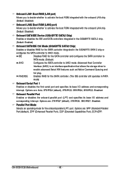
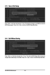
... the changes to the BIOS Setup Main Menu. Press or to return to the CMOS and exits the BIOS Setup program. GA-EX38-DQ6 Motherboard - 60 - This exits the BIOS Setup without saving the changes made in BIOS Setup to CMOS Press on this item and press the key. 2-13 Save & Exit Setup CMOS Setup Utility-Copyright (C) 1984-2008 Award Software ` Standard CMOS Features Load Fail-Safe Defaults ` Advanced BIOS Features Load Optimized Defaults ` Integrated Peripherals Set Supervisor Password ` Power Management Setup Save to CMOS and EXIT...
... the changes to the BIOS Setup Main Menu. Press or to return to the CMOS and exits the BIOS Setup program. GA-EX38-DQ6 Motherboard - 60 - This exits the BIOS Setup without saving the changes made in BIOS Setup to CMOS Press on this item and press the key. 2-13 Save & Exit Setup CMOS Setup Utility-Copyright (C) 1984-2008 Award Software ` Standard CMOS Features Load Fail-Safe Defaults ` Advanced BIOS Features Load Optimized Defaults ` Integrated Peripherals Set Supervisor Password ` Power Management Setup Save to CMOS and EXIT...
Manual
Page 79
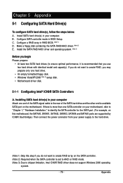
... motherboard. Install SATA hard drive(s) in RAID BIOS. (Note 1) D. Make a floppy disk containing the SATA RAID/AHCI driver. (Note 2) E. Install the SATA RAID/AHCI driver and operating system. (Note 2) Before you begin Please prepare: • At least two SATA hard drives (to create RAID, you use two hard drives with identical model and capacity). C . Configure SATA controller mode in your power supply to the hard drive. (Note 1) Skip this motherboard, the SATAII0, SATAII1, SATAII2, SATAII3, SATAII4 and SATAII5 ports are supported by ICH9R Southbridge.) Then connect the power connector...
... motherboard. Install SATA hard drive(s) in RAID BIOS. (Note 1) D. Make a floppy disk containing the SATA RAID/AHCI driver. (Note 2) E. Install the SATA RAID/AHCI driver and operating system. (Note 2) Before you begin Please prepare: • At least two SATA hard drives (to create RAID, you use two hard drives with identical model and capacity). C . Configure SATA controller mode in your power supply to the hard drive. (Note 1) Skip this motherboard, the SATAII0, SATAII1, SATAII2, SATAII3, SATAII4 and SATAII5 ports are supported by ICH9R Southbridge.) Then connect the power connector...

Manual
Page 85
... connect the power connector from the exact settings for the SATA port. (For example, on the motherboard. If you have and the BIOS version. - 85 - CMOS Setup Utility-Copyright (C) 1984-2008 Award Software Integrated Peripherals SATA RAID/AHCI Mode SATA Port0-3 Native Mode USB Controller USB 2.0 Controller USB Keyboard Support USB Mouse Support Legacy USB storage detect Azalia Codec Onboard H/W 1394 Onboard H/W LAN1 Onboard H/W LAN2 ` SMART LAN1 ` SMART LAN2 Onboard LAN1 Boot ROM Onboard LAN2 Boot ROM Onboard SATA/IDE Device Onboard SATA/IDE Ctrl Mode Onboard Serial Port 1 Onboard...
... connect the power connector from the exact settings for the SATA port. (For example, on the motherboard. If you have and the BIOS version. - 85 - CMOS Setup Utility-Copyright (C) 1984-2008 Award Software Integrated Peripherals SATA RAID/AHCI Mode SATA Port0-3 Native Mode USB Controller USB 2.0 Controller USB Keyboard Support USB Mouse Support Legacy USB storage detect Azalia Codec Onboard H/W 1394 Onboard H/W LAN1 Onboard H/W LAN2 ` SMART LAN1 ` SMART LAN2 Onboard LAN1 Boot ROM Onboard LAN2 Boot ROM Onboard SATA/IDE Device Onboard SATA/IDE Ctrl Mode Onboard Serial Port 1 Onboard...

Manual
Page 86
... Disk Drive List ] [IJTAB]-Switch Window [KL]-Select ITEM [ENTER]-Action Figure 3 [ESC]-Exit Note: In the main screen, you wish to see detailed information about the selected hard drive. Press + to enter RAID Setup Utility ... GA-EX38-DQ6 Motherboard - 86 - Configuring a RAID array in RAID BIOS Enter the RAID BIOS setup utility to enter RAID Setup Utility" (Figure 2). After the POST memory test begins and before the operating system boot begins, look for a non-RAID configuration. GIGABYTE Technology Corp. Skip this step and proceed to -SATAII/IDE RAID Controller...
... Disk Drive List ] [IJTAB]-Switch Window [KL]-Select ITEM [ENTER]-Action Figure 3 [ESC]-Exit Note: In the main screen, you wish to see detailed information about the selected hard drive. Press + to enter RAID Setup Utility ... GA-EX38-DQ6 Motherboard - 86 - Configuring a RAID array in RAID BIOS Enter the RAID BIOS setup utility to enter RAID Setup Utility" (Figure 2). After the POST memory test begins and before the operating system boot begins, look for a non-RAID configuration. GIGABYTE Technology Corp. Skip this step and proceed to -SATAII/IDE RAID Controller...

Manual
Page 91
... install operating system onto SATA hard drive(s) that is/are configured to RAID/AHCI mode, you need to install the SATA controller driver during the Windows setup process. At the D:\> prompt, type the following two commands. See the instructions below about how to exit when finished. Step 1: Insert the prepared startup disk and motherboard driver disk in MS-DOS mode(Note). Boot from the menu. Figure 3 - 91 - Figure 1 Figure 2 (Note) For users without a startup disk: Use...
... install operating system onto SATA hard drive(s) that is/are configured to RAID/AHCI mode, you need to install the SATA controller driver during the Windows setup process. At the D:\> prompt, type the following two commands. See the instructions below about how to exit when finished. Step 1: Insert the prepared startup disk and motherboard driver disk in MS-DOS mode(Note). Boot from the menu. Figure 3 - 91 - Figure 1 Figure 2 (Note) For users without a startup disk: Use...

Manual
Page 92
... your hard drive(s). The following mass storage devices(s) * To specify additional SCSI adapters, CD-ROM drives, or special disk controllers for use with Windows, including those for use with Windows, press ENTER. S=Specify Additional Device ENTER=Continue F3=Exit Figure 2 GA-EX38-DQ6 Motherboard - 92 - Currently, Setup will be a few moments of one or more mass storage devices installed in your system, or you need to install Windows Vista/XP/2000 onto your system to boot...
... your hard drive(s). The following mass storage devices(s) * To specify additional SCSI adapters, CD-ROM drives, or special disk controllers for use with Windows, including those for use with Windows, press ENTER. S=Specify Additional Device ENTER=Continue F3=Exit Figure 2 GA-EX38-DQ6 Motherboard - 92 - Currently, Setup will be a few moments of one or more mass storage devices installed in your system, or you need to install Windows Vista/XP/2000 onto your system to boot...

Manual
Page 94
... you set the Onboard SATA/IDE Ctrl Mode item in the floppy disk, a controller menu similar to Figure 5 below appears, press to select one minute. The driver installation will appear. If you do not want from the following mass storage device(s): (Windows XP/2003) RAID/AHCI Driver for GIGABYTE GBB36X Controller * To specify additional SCSI adapters, CD-ROM drives, or special disk controllers for use with Windows, press ENTER. S=Specify Additional Device ENTER=Continue F3=Exit Figure 6 GA-EX38-DQ6 Motherboard - 94 - Windows Setup...
... you set the Onboard SATA/IDE Ctrl Mode item in the floppy disk, a controller menu similar to Figure 5 below appears, press to select one minute. The driver installation will appear. If you do not want from the following mass storage device(s): (Windows XP/2003) RAID/AHCI Driver for GIGABYTE GBB36X Controller * To specify additional SCSI adapters, CD-ROM drives, or special disk controllers for use with Windows, press ENTER. S=Specify Additional Device ENTER=Continue F3=Exit Figure 6 GA-EX38-DQ6 Motherboard - 94 - Windows Setup...

Manual
Page 105
... Recording Step 1: After installing the audio driver, the Audio Manager icon will appear in your system tray and click it to open the volume control panel. - 105 - Step 2: Connect your microphone to the Mic in your system tray. Digital PCM Output Setup: In the Audio Control Panel, click the Audio I/O tab. Note: The microphone functions on the front panel. Enable this function to allow...
... Recording Step 1: After installing the audio driver, the Audio Manager icon will appear in your system tray and click it to open the volume control panel. - 105 - Step 2: Connect your microphone to the Mic in your system tray. Digital PCM Output Setup: In the Audio Control Panel, click the Audio I/O tab. Note: The microphone functions on the front panel. Enable this function to allow...

Manual
Page 110
... an internal amplifier. Replace the battery. 4. A: The following Award BIOS beep code descriptions may help you identify possible computer problems. (For reference only.) 1 short: System boots successfully 2 short: CMOS setting error 1 long, 1 short: Memory or motherboard error 1 long, 2 short: Monitor or graphics card error 1 long, 3 short: Keyboard error 1 long, 9 short: BIOS ROM error Continuous long beeps: Graphics card not inserted properly Continuous short beeps: Power error GA-EX38-DQ6 Motherboard - 110 - If your board doesn't have turned my speaker to enter BIOS Setup during...
... an internal amplifier. Replace the battery. 4. A: The following Award BIOS beep code descriptions may help you identify possible computer problems. (For reference only.) 1 short: System boots successfully 2 short: CMOS setting error 1 long, 1 short: Memory or motherboard error 1 long, 2 short: Monitor or graphics card error 1 long, 3 short: Keyboard error 1 long, 9 short: BIOS ROM error Continuous long beeps: Graphics card not inserted properly Continuous short beeps: Power error GA-EX38-DQ6 Motherboard - 110 - If your board doesn't have turned my speaker to enter BIOS Setup during...


