Manual
Page 1
GA-EP45T-UD3R/ GA-EP45T-UD3 LGA775 socket motherboard for Intel® CoreTM processor family/ Intel® Pentium® processor family/Intel® Celeron® processor family User's Manual Rev. 1002 12ME-EP45TUD3R-1002R
GA-EP45T-UD3R/ GA-EP45T-UD3 LGA775 socket motherboard for Intel® CoreTM processor family/ Intel® Pentium® processor family/Intel® Celeron® processor family User's Manual Rev. 1002 12ME-EP45TUD3R-1002R
Manual
Page 2
Motherboard GA-EP45T-UD3R/GA-EP45T-UD3 Oct. 2, 2008 Motherboard GA-EP45T-UD3R/ GA-EP45T-UD3 Oct. 2, 2008
Motherboard GA-EP45T-UD3R/GA-EP45T-UD3 Oct. 2, 2008 Motherboard GA-EP45T-UD3R/ GA-EP45T-UD3 Oct. 2, 2008
Manual
Page 4
Table of Contents Box Contents ...6 Optional Items...6 GA-EP45T-UD3R/UD3 Motherboard Layout 7 Block Diagram...8 Chapter 1 Hardware Installation 9 1-1 Installation Precautions 9 1-2 Product Specifications 10 1-3 Installing the CPU and CPU Cooler 13 1-3-1 Installing the CPU 13 1-3-2 Installing ...
Table of Contents Box Contents ...6 Optional Items...6 GA-EP45T-UD3R/UD3 Motherboard Layout 7 Block Diagram...8 Chapter 1 Hardware Installation 9 1-1 Installation Precautions 9 1-2 Product Specifications 10 1-3 Installing the CPU and CPU Cooler 13 1-3-1 Installing the CPU 13 1-3-2 Installing ...
Manual
Page 5
... Advanced 79 4-5 Q-Share ...81 4-6 Time Repair ...82 Chapter 5 Appendix ...83 5-1 Configuring SATA Hard Drive(s 83 5-1-1 Configuring Intel ICH10R SATA Controllers 83 5-1-2 Configuring GIGABYTE SATA2 SATA Controller 89 5-1-3 Making a SATA RAID/AHCI Driver Diskette 95 5-1-4 Installing the SATA RAID/AHCI Driver and Operating System 97 5-2 Configuring AudioInput and Output... Recording 108 5-2-4 Using the Sound Recorder 110 5-3 Troubleshooting 111 5-3-1 Frequently Asked Questions 111 5-3-2 Troubleshooting Procedure 112 5-4 Regulatory Statements 114 Only for GA-EP45T-UD3R. - 5 -
... Advanced 79 4-5 Q-Share ...81 4-6 Time Repair ...82 Chapter 5 Appendix ...83 5-1 Configuring SATA Hard Drive(s 83 5-1-1 Configuring Intel ICH10R SATA Controllers 83 5-1-2 Configuring GIGABYTE SATA2 SATA Controller 89 5-1-3 Making a SATA RAID/AHCI Driver Diskette 95 5-1-4 Installing the SATA RAID/AHCI Driver and Operating System 97 5-2 Configuring AudioInput and Output... Recording 108 5-2-4 Using the Sound Recorder 110 5-3 Troubleshooting 111 5-3-1 Frequently Asked Questions 111 5-3-2 Troubleshooting Procedure 112 5-4 Regulatory Statements 114 Only for GA-EP45T-UD3R. - 5 -
Manual
Page 6
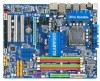
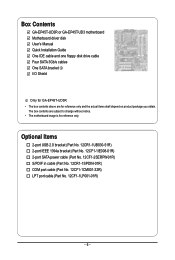
... 12CF1-1CM001-32R) LPT port cable (Part No. 12CF1-1LP001-01R) - 6 - The box contents are for reference only. Box Contents GA-EP45T-UD3R or GA-EP45T-UD3 motherboard Motherboard driver disk User's Manual Quick Installation Guide One IDE cable and one floppy disk drive cable Four SATA 3Gb/s cables One SATA... bracket I/O Shield Only for GA-EP45T-UD3R. • The box contents above are subject to change without notice. • The motherboard image is for reference only and the actual items...
... 12CF1-1CM001-32R) LPT port cable (Part No. 12CF1-1LP001-01R) - 6 - The box contents are for reference only. Box Contents GA-EP45T-UD3R or GA-EP45T-UD3 motherboard Motherboard driver disk User's Manual Quick Installation Guide One IDE cable and one floppy disk drive cable Four SATA 3Gb/s cables One SATA... bracket I/O Shield Only for GA-EP45T-UD3R. • The box contents above are subject to change without notice. • The motherboard image is for reference only and the actual items...
Manual
Page 7
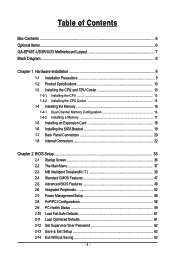
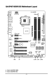
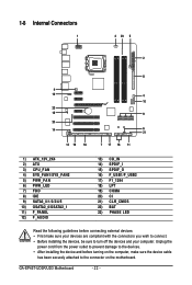
GA-EP45T-UD3R/UD3 DDR3_1 DDR3_2 DDR3_3 DDR3_4 GSATA2_0 GSATA2_1 GA-EP45T-UD3R/UD3 Motherboard Layout KB_MS CPU_FAN R_SPDIF ATX_12V_2X4 LGA775 PHASE LED ATX USB_1394_2 PWR_FAN USB_1394_1 R_USB USB_LAN AUDIO F_AUDIO SYS_FAN1 PCIEX1_1 RTL8111C PCIEX16 PCIEX1_2 CODEC PCIEX1_3 BAT SPDIF_O CI PCI1 IT8718 SPDIF_I PCI2 PCI3 CD_IN Intel® P45 IDE SYS_FAN2 GIGABYTE Intel® ICH10R SATA2...
GA-EP45T-UD3R/UD3 DDR3_1 DDR3_2 DDR3_3 DDR3_4 GSATA2_0 GSATA2_1 GA-EP45T-UD3R/UD3 Motherboard Layout KB_MS CPU_FAN R_SPDIF ATX_12V_2X4 LGA775 PHASE LED ATX USB_1394_2 PWR_FAN USB_1394_1 R_USB USB_LAN AUDIO F_AUDIO SYS_FAN1 PCIEX1_1 RTL8111C PCIEX16 PCIEX1_2 CODEC PCIEX1_3 BAT SPDIF_O CI PCI1 IT8718 SPDIF_I PCI2 PCI3 CD_IN Intel® P45 IDE SYS_FAN2 GIGABYTE Intel® ICH10R SATA2...
Manual
Page 8
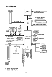
... CLK (100 MHz) x1 x1 x1 LAN RJ45 RTL 8111C x1 PCI Express Bus 2 SATA 3Gb/s ATA-133/100/66/ 33 IDE Channel PCI Bus GIGABYTE SATA2 TSB43AB23 3 IEEE 1394a Host Interface DDR3 2200/1600/1333/ 1066/800 MHz Intel® P45 Dual Channel Memory MCH CLK (400/333/266/200... Out Center/Subwoofer Speaker Out Side Speaker Out MIC Line-Out Line-In SPDIF In SPDIF Out 3 PCI PCI CLK (33 MHz) Only for GA-EP45T-UD3R. Only for GA-EP45T-UD3. - 8 -
... CLK (100 MHz) x1 x1 x1 LAN RJ45 RTL 8111C x1 PCI Express Bus 2 SATA 3Gb/s ATA-133/100/66/ 33 IDE Channel PCI Bus GIGABYTE SATA2 TSB43AB23 3 IEEE 1394a Host Interface DDR3 2200/1600/1333/ 1066/800 MHz Intel® P45 Dual Channel Memory MCH CLK (400/333/266/200... Out Center/Subwoofer Speaker Out Side Speaker Out MIC Line-Out Line-In SPDIF In SPDIF Out 3 PCI PCI CLK (33 MHz) Only for GA-EP45T-UD3R. Only for GA-EP45T-UD3. - 8 -
Manual
Page 10
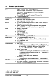
... to 3 IEEE 1394a ports (2 on the back panel, 1 via the IEEE 1394a bracket connected to the internal IEEE 1394a header) Only for GA-EP45T-UD3R. Only for CD In 1 x Realtek 8111C chip (10/100/1000 Mbit) 1 x PCI Express x16 slot, running at... disk drive T.I. Support for SATA RAID 0, RAID 1, RAID 5 and RAID 10 GIGABYTE SATA2 chip: - 1 x IDE connector supporting ATA-133/100/66/33 and up to 2 IDE devices - 2 x SATA 3Gb/s connectors (GSATA2_0, GSATA2_1) supporting up to 2 SATA 3Gb/s devices - GA-EP45T-UD3R/UD3 Motherboard - 10 -
... to 3 IEEE 1394a ports (2 on the back panel, 1 via the IEEE 1394a bracket connected to the internal IEEE 1394a header) Only for GA-EP45T-UD3R. Only for CD In 1 x Realtek 8111C chip (10/100/1000 Mbit) 1 x PCI Express x16 slot, running at... disk drive T.I. Support for SATA RAID 0, RAID 1, RAID 5 and RAID 10 GIGABYTE SATA2 chip: - 1 x IDE connector supporting ATA-133/100/66/33 and up to 2 IDE devices - 2 x SATA 3Gb/s connectors (GSATA2_0, GSATA2_1) supporting up to 2 SATA 3Gb/s devices - GA-EP45T-UD3R/UD3 Motherboard - 10 -
Manual
Page 12
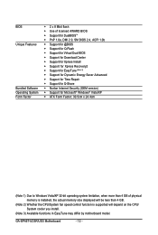
... fan speed control function is supported will depend on the CPU/ System cooler you install. (Note 3) Available functions in EasyTune may differ by motherboard model. GA-EP45T-UD3R/UD3 Motherboard - 12 -
... fan speed control function is supported will depend on the CPU/ System cooler you install. (Note 3) Available functions in EasyTune may differ by motherboard model. GA-EP45T-UD3R/UD3 Motherboard - 12 -
Manual
Page 14
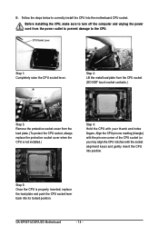
.... Step 5: Once the CPU is not installed.) Step 4: Hold the CPU with the socket alignment keys) and gently insert the CPU into its locked position. GA-EP45T-UD3R/UD3 Motherboard - 14 - CPU Socket Lever Step 1: Completely raise the CPU socket lever. Follow the steps below to the CPU. B. Align the CPU pin one...
.... Step 5: Once the CPU is not installed.) Step 4: Hold the CPU with the socket alignment keys) and gently insert the CPU into its locked position. GA-EP45T-UD3R/UD3 Motherboard - 14 - CPU Socket Lever Step 1: Completely raise the CPU socket lever. Follow the steps below to the CPU. B. Align the CPU pin one...
Manual
Page 16
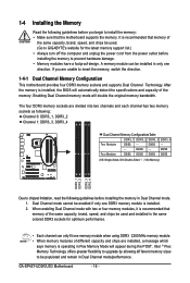
... using DDR3 2200 MHz memory module. • When memory modules of the same capacity, brand, speed, and chips be used . (Go to GIGABYTE's website for optimum performance. • Each channel can be populated and remain in Dual Channel mode. 1. Dual Channel mode cannot be used and ...before installing the memory to prevent hardware damage. • Memory modules have a foolproof design. After the memory is recommended that memory of the memory. GA-EP45T-UD3R/UD3 Motherboard - 16 - DS/SS Four Modules DS/SS DS/SS DS/SS DS/SS (SS=Single-Sided, DS=Double-Sided, "- -"=No ...
... using DDR3 2200 MHz memory module. • When memory modules of the same capacity, brand, speed, and chips be used . (Go to GIGABYTE's website for optimum performance. • Each channel can be populated and remain in Dual Channel mode. 1. Dual Channel mode cannot be used and ...before installing the memory to prevent hardware damage. • Memory modules have a foolproof design. After the memory is recommended that memory of the memory. GA-EP45T-UD3R/UD3 Motherboard - 16 - DS/SS Four Modules DS/SS DS/SS DS/SS DS/SS (SS=Single-Sided, DS=Double-Sided, "- -"=No ...
Manual
Page 18
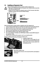
... install an expansion card: • Make sure the motherboard supports the expansion card. Install the driver provided with your expansion card in your expansion card(s). 7. GA-EP45T-UD3R/UD3 Motherboard - 18 - 1-5 Installing an Expansion Card Read the following guidelines before installing an expansion card to prevent hardware damage. If necessary, go to BIOS...
... install an expansion card: • Make sure the motherboard supports the expansion card. Install the driver provided with your expansion card in your expansion card(s). 7. GA-EP45T-UD3R/UD3 Motherboard - 18 - 1-5 Installing an Expansion Card Read the following guidelines before installing an expansion card to prevent hardware damage. If necessary, go to BIOS...
Manual
Page 19
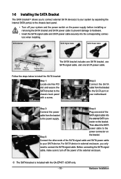
... cable from the bracket to hardware. • Insert the SATA signal cable and SATA power cable securely into to the chassis back panel with the GA-EP45T -UD3R only. - 19 - Hardware Installation Follow the steps below to install the SA TA bracket: Step 1: Locate one free PCI slot and secure the SATA bracket...
... cable from the bracket to hardware. • Insert the SATA signal cable and SATA power cable securely into to the chassis back panel with the GA-EP45T -UD3R only. - 19 - Hardware Installation Follow the steps below to install the SA TA bracket: Step 1: Locate one free PCI slot and secure the SATA bracket...
Manual
Page 20
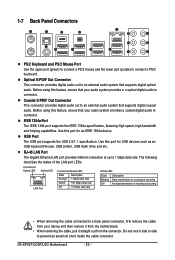
..., ensure that your audio system provides a coaxial digital audio in connector. Use this feature, ensure that your audio system provides a n optical digital audio in connector. GA-EP45T-UD3R/UD3 Motherboard - 20 - IEEE 1394a Port The IEEE 1394 port supports the IEEE 1394a specification, featuring high speed, high bandwidth and hotplug capabilities. Before using...
..., ensure that your audio system provides a coaxial digital audio in connector. Use this feature, ensure that your audio system provides a n optical digital audio in connector. GA-EP45T-UD3R/UD3 Motherboard - 20 - IEEE 1394a Port The IEEE 1394 port supports the IEEE 1394a specification, featuring high speed, high bandwidth and hotplug capabilities. Before using...
Manual
Page 22
... devices are compliant with the connectors you wish to connect. • Before installing the devices, be sure to turn off the devices and your computer. GA-EP45T-UD3R/UD3 Motherboard - 22 -
... devices are compliant with the connectors you wish to connect. • Before installing the devices, be sure to turn off the devices and your computer. GA-EP45T-UD3R/UD3 Motherboard - 22 -
Manual
Page 24
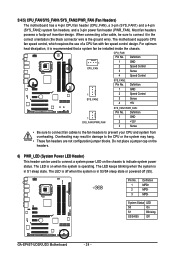
System Status LED S0 On S1 Blinking S3/S4/S5 Off GA-EP45T-UD3R/UD3 Motherboard - 24 - 3/4/5) CPU_FAN/SYS_FAN1/SYS_FAN2/PWR_FAN (Fan Headers) The motherboard has a 4-pin CPU fan header (CPU_FAN), a 3-pin (SYS_FAN1) and a 4-pin (SYS_FAN2) system fan headers, ...
System Status LED S0 On S1 Blinking S3/S4/S5 Off GA-EP45T-UD3R/UD3 Motherboard - 24 - 3/4/5) CPU_FAN/SYS_FAN1/SYS_FAN2/PWR_FAN (Fan Headers) The motherboard has a 4-pin CPU fan header (CPU_FAN), a 3-pin (SYS_FAN1) and a 4-pin (SYS_FAN2) system fan headers, ...

Manual
Page 26
... GND RXN RXP GND Only for instructions on configuring a RAID array. Refer to Chapter 5, "Configuring SA TA Hard Drive(s)," for GA-EP45T-UD3. Each SATA connector supports a single SA TA device. GA-EP45T-UD3R/UD3 Motherboard - 26 - Definition 1 GND 2 TXP SATA2_4 SATA2_2 SATA2_0 3 TXN 7 1 4 GND 5 RXN 7 1 6... RXP SATA2_5 SATA2_3 SATA2_1 7 GND Only for GA-EP45T-UD3R. Please connect the L-shaped end of hard drives must be an even number. • A RAID 5 configuration requires at least three hard ...
... GND RXN RXP GND Only for instructions on configuring a RAID array. Refer to Chapter 5, "Configuring SA TA Hard Drive(s)," for GA-EP45T-UD3. Each SATA connector supports a single SA TA device. GA-EP45T-UD3R/UD3 Motherboard - 26 - Definition 1 GND 2 TXP SATA2_4 SATA2_2 SATA2_0 3 TXN 7 1 4 GND 5 RXN 7 1 6... RXP SATA2_5 SATA2_3 SATA2_1 7 GND Only for GA-EP45T-UD3R. Please connect the L-shaped end of hard drives must be an even number. • A RAID 5 configuration requires at least three hard ...
Manual
Page 30
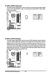
... S/PDIF digital audio cable, carefully read the manual for digital audio output from the HDMI display at the same time. Pin No. Definition 1 SPDIFO 1 2 GND GA-EP45T-UD3R/UD3 Motherboard - 30 - Pin No. Definition 1 Power 2 SPDIFI 3 GND 1 15) SPDIF_O (S/PDIF Out Header) This header supports digital S/PDIF out and connects a S/PDIF digital audio...
... S/PDIF digital audio cable, carefully read the manual for digital audio output from the HDMI display at the same time. Pin No. Definition 1 SPDIFO 1 2 GND GA-EP45T-UD3R/UD3 Motherboard - 30 - Pin No. Definition 1 Power 2 SPDIFI 3 GND 1 15) SPDIF_O (S/PDIF Out Header) This header supports digital S/PDIF out and connects a S/PDIF digital audio...

Manual
Page 32
... LPT port cable. For purchasing the optional COM port cable, please contact the local dealer. 9 1 10 2 Pin No. 1 2 3 4 5 6 7 8 9 10 Definition NDCDNSIN NSOUT NDTRGND NDSRNRTSNCTSNRINo Pin GA-EP45T-UD3R/UD3 Motherboard - 32 -
... LPT port cable. For purchasing the optional COM port cable, please contact the local dealer. 9 1 10 2 Pin No. 1 2 3 4 5 6 7 8 9 10 Definition NDCDNSIN NSOUT NDTRGND NDSRNRTSNCTSNRINo Pin GA-EP45T-UD3R/UD3 Motherboard - 32 -
Manual
Page 34
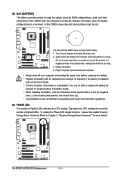
... the orientation of the positive side (+) and the negative side (-) of the battery (the positive side should face up). • Used batteries must be lost. GA-EP45T-UD3R/UD3 Motherboard - 34 - 22) BAT (BATTERY) The battery provides power to keep the values (such as BIOS configurations, date, and time information) in the power...
... the orientation of the positive side (+) and the negative side (-) of the battery (the positive side should face up). • Used batteries must be lost. GA-EP45T-UD3R/UD3 Motherboard - 34 - 22) BAT (BATTERY) The battery provides power to keep the values (such as BIOS configurations, date, and time information) in the power...

