
Manual
Page 4
... ...6 OptionalItems...6 GA-EP45-UD3LR/GA-EP45-UD3L Motherboard Layout 7 Block Diagram...8 Chapter 1 Hardware Installation 9 1-1 Installation Precautions 9 1-2 Product Specifications 10 1-3 Installing the CPU and CPU Cooler 13 1-3-1 Installing the CPU 13 1-3-2 Installing the CPU Cooler 15 1-4 Installing the Memory 16 1-4-1 Dual Channel Memory Configuration 16 1-4-2 Installing a Memory 17 1-5 Installing an Expansion Card 18 1-6 Back Panel Connectors 19...
... ...6 OptionalItems...6 GA-EP45-UD3LR/GA-EP45-UD3L Motherboard Layout 7 Block Diagram...8 Chapter 1 Hardware Installation 9 1-1 Installation Precautions 9 1-2 Product Specifications 10 1-3 Installing the CPU and CPU Cooler 13 1-3-1 Installing the CPU 13 1-3-2 Installing the CPU Cooler 15 1-4 Installing the Memory 16 1-4-1 Dual Channel Memory Configuration 16 1-4-2 Installing a Memory 17 1-5 Installing an Expansion Card 18 1-6 Back Panel Connectors 19...

Manual
Page 10
...Intel® Celeron® processor in the South Bridge Up to 12 USB 2.0/1.1 ports (8 on the back panel, 4 via the USB brackets connected to 6 SATA 3Gb/s devices - Only for GA-EP45-UD3LR. Support for SATA RAID 0, RAID 1, RAID 5 and RAID 10 JMicron 368 chip: - 1 x ... of system memory (Note 1) Dual channel memory architecture Support for DDR2 1366/1066/800/667 MHz memory modules (Go to GIGABYTE's website for the latest memory support list.) Realtek ALC888 codec High Definition Audio 2/4/5.1/7.1-channel Support for S/...
...Intel® Celeron® processor in the South Bridge Up to 12 USB 2.0/1.1 ports (8 on the back panel, 4 via the USB brackets connected to 6 SATA 3Gb/s devices - Only for GA-EP45-UD3LR. Support for SATA RAID 0, RAID 1, RAID 5 and RAID 10 JMicron 368 chip: - 1 x ... of system memory (Note 1) Dual channel memory architecture Support for DDR2 1366/1066/800/667 MHz memory modules (Go to GIGABYTE's website for the latest memory support list.) Realtek ALC888 codec High Definition Audio 2/4/5.1/7.1-channel Support for S/...
Manual
Page 11
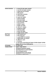
...3Gb/s connectors 1 x CPU fan header 2 x system fan headers 1 x power fan header 1 x front panel header 1 x front panel audio header 1 x CD In connector 1 x S/PDIF In header 1 x S/PDIF Out header 2 x...2.0/1.1 headers 1 x parallel port header 1 x serial port header 1 x power LED header 1 x chassis intrusion header Back Panel 1 x PS/2 keyboard port Connectors 1 x PS/2 mouse port 1 x coaxial S/PDIF Out connector 1 x optical S/PDIF...
...3Gb/s connectors 1 x CPU fan header 2 x system fan headers 1 x power fan header 1 x front panel header 1 x front panel audio header 1 x CD In connector 1 x S/PDIF In header 1 x S/PDIF Out header 2 x...2.0/1.1 headers 1 x parallel port header 1 x serial port header 1 x power LED header 1 x chassis intrusion header Back Panel 1 x PS/2 keyboard port Connectors 1 x PS/2 mouse port 1 x coaxial S/PDIF Out connector 1 x optical S/PDIF...

Manual
Page 18
...Setup to correctly install your expansion card. • Always turn off the computer and unplug the power cord from the chassis back panel. 2. Carefully read the manual that supports your operating system. PCI Express x1 Slot PCI Express x16 Slot PCI Slot Follow the steps...install an expansion card: • Make sure the motherboard supports the expansion card. After installing all expansion cards, replace the chassis cover(s). 6. GA-EP45-UD3LR/UD3L Motherboard - 18 - Make sure the card is fully inserted into the slot. 4. Align the card with your expansion card in the...
...Setup to correctly install your expansion card. • Always turn off the computer and unplug the power cord from the chassis back panel. 2. Carefully read the manual that supports your operating system. PCI Express x1 Slot PCI Express x16 Slot PCI Slot Follow the steps...install an expansion card: • Make sure the motherboard supports the expansion card. After installing all expansion cards, replace the chassis cover(s). 6. GA-EP45-UD3LR/UD3L Motherboard - 18 - Make sure the card is fully inserted into the slot. 4. Align the card with your expansion card in the...
Manual
Page 19
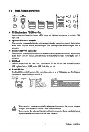
... to an external audio system that supports digital optical audio. Optical S/PDIF Out Connector This connector provides digital audio out to a back panel connector, first remove the cable from the connector. RJ-45 LAN Port The Gigabit Ethernet LAN port provides Internet connection at up to... digital coaxial audio. USB Port The USB port supports the USB 2.0/1.1 specification. The following describes the states of the LAN port LEDs. 1-6 Back Panel Connectors PS/2 Keyboard and PS/2 Mouse Port Use the upper port (green) to connect a PS/2 mouse and the lower port (purple) to...
... to an external audio system that supports digital optical audio. Optical S/PDIF Out Connector This connector provides digital audio out to a back panel connector, first remove the cable from the connector. RJ-45 LAN Port The Gigabit Ethernet LAN port provides Internet connection at up to... digital coaxial audio. USB Port The USB port supports the USB 2.0/1.1 specification. The following describes the states of the LAN port LEDs. 1-6 Back Panel Connectors PS/2 Keyboard and PS/2 Mouse Port Use the upper port (green) to connect a PS/2 mouse and the lower port (purple) to...
Manual
Page 26
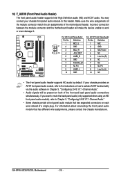
... of a single plug. For information about connecting the front panel audio module that has separated connectors on both of the motherboard header. GA-EP45-UD3LR/UD3L Motherboard - 26 - If your chassis front panel audio module to this header. 10) F_AUDIO (Front Panel Audio Header) The front panel audio header supports Intel High Definition audio (HD) and AC...
... of a single plug. For information about connecting the front panel audio module that has separated connectors on both of the motherboard header. GA-EP45-UD3LR/UD3L Motherboard - 26 - If your chassis front panel audio module to this header. 10) F_AUDIO (Front Panel Audio Header) The front panel audio header supports Intel High Definition audio (HD) and AC...

Manual
Page 27
...the problem. Refer to Chapter 5, "Troubleshooting," for more information). • SPEAK (Speaker, Orange): Connects to the speaker on the chassis front panel. A front panel module mainly consists of power switch, reset switch, power LED, hard drive activity LED, speaker and etc. Message/Power/ Power Sleep LED Switch ... information about beep codes. • HD (Hard Drive Activity LED, Blue) Connects to the hard drive activity LED on the chassis front panel. The S0 On LED is on when the system is in S1 sleep state. Note the positive and negative pins before connecting the cables...
...the problem. Refer to Chapter 5, "Troubleshooting," for more information). • SPEAK (Speaker, Orange): Connects to the speaker on the chassis front panel. A front panel module mainly consists of power switch, reset switch, power LED, hard drive activity LED, speaker and etc. Message/Power/ Power Sleep LED Switch ... information about beep codes. • HD (Hard Drive Activity LED, Blue) Connects to the hard drive activity LED on the chassis front panel. The S0 On LED is on when the system is in S1 sleep state. Note the positive and negative pins before connecting the cables...

Manual
Page 92
...jack, you want to mute the back panel audio (only supported when using an HD front panel audio module), refer to be present on both of the front and back panel audio connections simultaneously. all at the same time. GA-EP45-UD3LR/UD3L Motherboard - 92 - Side Speaker ...Out Mic In For example, in and out) to instructions on the back panel which support 2/4/5.1/7.1-channel audio. Configuring Speakers: (The...
...jack, you want to mute the back panel audio (only supported when using an HD front panel audio module), refer to be present on both of the front and back panel audio connections simultaneously. all at the same time. GA-EP45-UD3LR/UD3L Motherboard - 92 - Side Speaker ...Out Mic In For example, in and out) to instructions on the back panel which support 2/4/5.1/7.1-channel audio. Configuring Speakers: (The...

Manual
Page 93
... configure an audio environment on the Audio I /O tab. Activating an AC'97 Front Panel Audio Module: If your chassis provides an AC'97 front panel audio module, to an audio jack, the Connected device box appears. Muting the Back Panel Audio (For HD Audio Only): Click the tool icon on the Sound Effect... tab. On the Connector Settings box, select the Mute rear panel output when front headphone plugged in check box. Appendix Step 3: Everytime you connect an audio device to activate the AC'97 functionality, click the tool ...
... configure an audio environment on the Audio I /O tab. Activating an AC'97 Front Panel Audio Module: If your chassis provides an AC'97 front panel audio module, to an audio jack, the Connected device box appears. Muting the Back Panel Audio (For HD Audio Only): Click the tool icon on the Sound Effect... tab. On the Connector Settings box, select the Mute rear panel output when front headphone plugged in check box. Appendix Step 3: Everytime you connect an audio device to activate the AC'97 functionality, click the tool ...

Manual
Page 94
5-2-2 Installing the S/PDIF In Cable (Optional) The S/PDIF in cable provides S/PDIF in jacks allow you to input digital audio signals to the SPDIF_I header on your motherboard. GA-EP45-UD3LR/UD3L Motherboard - 94 - Optical S/PDIF In Coaxial S/PDIF In S/PDIF In: The S/PDIF in functionality. Installing the S/PDIF In Cable: Step 1: First, attach the connector at the end of the cable to the computer for audio processing. A. Step 2: Secure the metal bracket to the chassis back panel with a screw.
5-2-2 Installing the S/PDIF In Cable (Optional) The S/PDIF in cable provides S/PDIF in jacks allow you to input digital audio signals to the SPDIF_I header on your motherboard. GA-EP45-UD3LR/UD3L Motherboard - 94 - Optical S/PDIF In Coaxial S/PDIF In S/PDIF In: The S/PDIF in functionality. Installing the S/PDIF In Cable: Step 1: First, attach the connector at the end of the cable to the computer for audio processing. A. Step 2: Secure the metal bracket to the chassis back panel with a screw.

Manual
Page 96
Step 2: Connect your microphone to open the volume control panel. Step 3: Locate the Volume icon in jack (pink) on the front panel and back panel cannot be used at the same time. 5-2-3 Configuring Microphone Recording Step 1: After installing the audio driver, the Audio Manager icon will appear ...in your system tray and click it to the Mic in jack (pink) on the back panel or the Mic in your system tray. Then configure the jack for microphone functionality. GA-EP45-UD3LR/UD3L Motherboard - 96 - Note: The microphone functions on the front...
Step 2: Connect your microphone to open the volume control panel. Step 3: Locate the Volume icon in jack (pink) on the front panel and back panel cannot be used at the same time. 5-2-3 Configuring Microphone Recording Step 1: After installing the audio driver, the Audio Manager icon will appear ...in your system tray and click it to the Mic in jack (pink) on the back panel or the Mic in your system tray. Then configure the jack for microphone functionality. GA-EP45-UD3LR/UD3L Motherboard - 96 - Note: The microphone functions on the front...

Manual
Page 97
...the Options menu and then choose Properties. To hear the sound being recorded during the recording process when using the microphone function on the back panel, do not select the Mute check box under Rear Pink In in Master Volume. In the Mixer device list, select Realtek HD Audio Input.... and click Properties. Step 4: To hear the sound being recorded during the record- ing process when using the microphone function on or the front panel, do not select the Mute check box under Front Pink In or Front Green In in Master Volume. Step 5: Next, while in the Mixer...
...the Options menu and then choose Properties. To hear the sound being recorded during the recording process when using the microphone function on the back panel, do not select the Mute check box under Rear Pink In in Master Volume. In the Mixer device list, select Realtek HD Audio Input.... and click Properties. Step 4: To hear the sound being recorded during the record- ing process when using the microphone function on or the front panel, do not select the Mute check box under Front Pink In or Front Green In in Master Volume. Step 5: Next, while in the Mixer...


