
Manual
Page 1
GA-EP45-DS4P/ GA-EP45-DS4 LGA775 socket motherboard for Intel® CoreTM processor family/ Intel® Pentium® processor family/Intel® Celeron® processor family User's Manual Rev. 1003 12ME-EP45DS4-1003R
GA-EP45-DS4P/ GA-EP45-DS4 LGA775 socket motherboard for Intel® CoreTM processor family/ Intel® Pentium® processor family/Intel® Celeron® processor family User's Manual Rev. 1003 12ME-EP45DS4-1003R
Manual
Page 2
Motherboard GA-EP45-DS4P/GA-EP45-DS4 May 15, 2008 Motherboard GA-EP45-DS4P/ GA-EP45-DS4 May 15, 2008
Motherboard GA-EP45-DS4P/GA-EP45-DS4 May 15, 2008 Motherboard GA-EP45-DS4P/ GA-EP45-DS4 May 15, 2008

Manual
Page 3
... product information, carefully read the User's Manual. „ For instructions on our website. Check your motherboard looks like this manual are legally registered to use GIGABYTE's unique features, read or download the information on/from the Support\Motherboard\Technology Guide page on how to their respective owners. The logo is designated by any...
... product information, carefully read the User's Manual. „ For instructions on our website. Check your motherboard looks like this manual are legally registered to use GIGABYTE's unique features, read or download the information on/from the Support\Motherboard\Technology Guide page on how to their respective owners. The logo is designated by any...

Manual
Page 4
Table of Contents Box Contents ...6 OptionalItems ...6 GA-EP45-DS4P/GA-EP45-DS4 Motherboard Layout 7 Block Diagram ...8 Chapter 1 Hardware Installation 9 1-1 Installation Precautions 9 1-2 Product Specifications 10 1-3 Installing the CPU and CPU Cooler 13 1-3-1 Installing the CPU 13 1-3-2 Installing the CPU ... 59 2-12 Set Supervisor/User Password 60 2-13 Save & Exit Setup 61 2-14 Exit Without Saving 61 2-15 Security Chip Configuration* (Note 62 "*" Only for GA-EP45-DS4P. - 4 -
Table of Contents Box Contents ...6 OptionalItems ...6 GA-EP45-DS4P/GA-EP45-DS4 Motherboard Layout 7 Block Diagram ...8 Chapter 1 Hardware Installation 9 1-1 Installation Precautions 9 1-2 Product Specifications 10 1-3 Installing the CPU and CPU Cooler 13 1-3-1 Installing the CPU 13 1-3-2 Installing the CPU ... 59 2-12 Set Supervisor/User Password 60 2-13 Save & Exit Setup 61 2-14 Exit Without Saving 61 2-15 Security Chip Configuration* (Note 62 "*" Only for GA-EP45-DS4P. - 4 -

Manual
Page 6
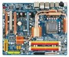
The box contents are for reference only. Box Contents GA-EP45-DS4P/GA-EP45-DS4 motherboard Motherboard driver disk User's Manual Quick Installation Guide Intel® LGA775 CPU Installation Guide One IDE cable and one floppy disk drive cable Four ...SATA 3Gb/s cables One SATA bracket I/O Shield • The box contents above are subject to change without notice. • The motherboard image is for reference ...
The box contents are for reference only. Box Contents GA-EP45-DS4P/GA-EP45-DS4 motherboard Motherboard driver disk User's Manual Quick Installation Guide Intel® LGA775 CPU Installation Guide One IDE cable and one floppy disk drive cable Four ...SATA 3Gb/s cables One SATA bracket I/O Shield • The box contents above are subject to change without notice. • The motherboard image is for reference ...

Manual
Page 7
GA-EP45-DS4P/GA-EP45-DS4 Motherboard Layout KB_MS SYS_FAN1 CPU_LED R_SPDIF USB_1394_2 ATX_12V_2X LGA775 CPU_FAN PHASE LED ACPI_LED (S0/1/3/4/5_LED) PWR_FAN USB_1394_1 GA-EP45-DS4P/DS4 DIMM_LED ATX USB_LAN2 USB_LAN1 RTL8111C F_AUDIO AUDIO PCIEX1_1 PE1_LED Intel® P45 RTL8111C PCIEX16_1 NB_FAN CODEC PCIEX1_2 M_BIOS PCIEX1_3 B_BIOS ... COMA CLR_CMOS PWR_LED SPDIF_I PW_SW CMOS_SW RST_SW F_PANEL TPM_IC*(Note) SYS_FAN2 F_1394 SATA2_5 SATA2_3 SA_LED F_USB2 F_USB1 SYS_FAN3 "*" Only for GA-EP45-DS4P. (Note) This feature is optional due to different regional policy. - 7 -
GA-EP45-DS4P/GA-EP45-DS4 Motherboard Layout KB_MS SYS_FAN1 CPU_LED R_SPDIF USB_1394_2 ATX_12V_2X LGA775 CPU_FAN PHASE LED ACPI_LED (S0/1/3/4/5_LED) PWR_FAN USB_1394_1 GA-EP45-DS4P/DS4 DIMM_LED ATX USB_LAN2 USB_LAN1 RTL8111C F_AUDIO AUDIO PCIEX1_1 PE1_LED Intel® P45 RTL8111C PCIEX16_1 NB_FAN CODEC PCIEX1_2 M_BIOS PCIEX1_3 B_BIOS ... COMA CLR_CMOS PWR_LED SPDIF_I PW_SW CMOS_SW RST_SW F_PANEL TPM_IC*(Note) SYS_FAN2 F_1394 SATA2_5 SATA2_3 SA_LED F_USB2 F_USB1 SYS_FAN3 "*" Only for GA-EP45-DS4P. (Note) This feature is optional due to different regional policy. - 7 -

Manual
Page 9
... on an uneven surface. • Do not place the computer system in a high-temperature environment. • Turning on the motherboard, make sure the power supply voltage has been set according to the local voltage standard. • Before using the product, please...these procedures: • Prior to the use of electrostatic discharge (ESD). Hardware Installation Chapter 1 Hardware Installation 1-1 Installation Precautions The motherboard contains numerous delicate electronic circuits and components which can lead to damage to system components as well as physical harm to the user....
... on an uneven surface. • Do not place the computer system in a high-temperature environment. • Turning on the motherboard, make sure the power supply voltage has been set according to the local voltage standard. • Before using the product, please...these procedures: • Prior to the use of electrostatic discharge (ESD). Hardware Installation Chapter 1 Hardware Installation 1-1 Installation Precautions The motherboard contains numerous delicate electronic circuits and components which can lead to damage to system components as well as physical harm to the user....

Manual
Page 10
... x PCI Express x1 slots Š 1 x PCI slot Š South Bridge: - 6 x SATA 3Gb/s connectors supporting up to the internal IEEE 1394a header) GA-EP45-DS4P/DS4 Motherboard - 10 - TSB43AB23 chip Š Up to 3 IEEE 1394a ports (2 on the back panel, 1 via the IEEE 1394a bracket connected to 1 floppy disk drive ...system memory (Note 1) Š Dual channel memory architecture Š Support for DDR2 1200/1066/800/667 MHz memory modules (Go to GIGABYTE's website for the latest memory support list.) Š Realtek ALC889A codec Š High Definition Audio Š 2/4/5.1/7.1-channel Š Support...
... x PCI Express x1 slots Š 1 x PCI slot Š South Bridge: - 6 x SATA 3Gb/s connectors supporting up to the internal IEEE 1394a header) GA-EP45-DS4P/DS4 Motherboard - 10 - TSB43AB23 chip Š Up to 3 IEEE 1394a ports (2 on the back panel, 1 via the IEEE 1394a bracket connected to 1 floppy disk drive ...system memory (Note 1) Š Dual channel memory architecture Š Support for DDR2 1200/1066/800/667 MHz memory modules (Go to GIGABYTE's website for the latest memory support list.) Š Realtek ALC889A codec Š High Definition Audio Š 2/4/5.1/7.1-channel Š Support...

Manual
Page 12
"*" Only for optimum performance. When it in EasyTune may differ by motherboard model. (Note 7) This feature is installed, the actual memory size displayed will depend on the CPU cooler you are installing one PCI Express graphics card, ... more than 4 GB. (Note 2) For Windows XP/Vista 32-bit operating system only. (Note 3) If you install. (Note 6) Available functions in the PCIEX16_1 slot for GA-EP45-DS4P. GA-EP45-DS4P/DS4 Motherboard - 12 -
"*" Only for optimum performance. When it in EasyTune may differ by motherboard model. (Note 7) This feature is installed, the actual memory size displayed will depend on the CPU cooler you are installing one PCI Express graphics card, ... more than 4 GB. (Note 2) For Windows XP/Vista 32-bit operating system only. (Note 3) If you install. (Note 6) Available functions in the PCIEX16_1 slot for GA-EP45-DS4P. GA-EP45-DS4P/DS4 Motherboard - 12 -

Manual
Page 13
... installed, otherwise overheating and damage of the CPU Socket Notch Notch Triangle Pin One Marking on the CPU. Hardware Installation mended that the motherboard supports the CPU. (Go to GIGABYTE's website for the peripherals. LGA775 CPU Socket Alignment Key LGA 775 CPU Alignment Key Pin One Corner of the CPU may locate...
... installed, otherwise overheating and damage of the CPU Socket Notch Notch Triangle Pin One Marking on the CPU. Hardware Installation mended that the motherboard supports the CPU. (Go to GIGABYTE's website for the peripherals. LGA775 CPU Socket Alignment Key LGA 775 CPU Alignment Key Pin One Corner of the CPU may locate...

Manual
Page 14
... the CPU with the socket alignment keys) and gently insert the CPU into position. GA-EP45-DS4P/DS4 Motherboard - 14 - Step 5: Once the CPU is properly inserted, replace the load plate and push the CPU socket lever back into the motherboard CPU socket. Step 2: Remove the protective socket cover. Align the CPU pin one marking...
... the CPU with the socket alignment keys) and gently insert the CPU into position. GA-EP45-DS4P/DS4 Motherboard - 14 - Step 5: Once the CPU is properly inserted, replace the load plate and push the CPU socket lever back into the motherboard CPU socket. Step 2: Remove the protective socket cover. Align the CPU pin one marking...

Manual
Page 15
... check the back of arrow is to the CPU. 1-3-2 Installing the CPU Cooler Follow the steps below to correctly install the CPU cooler on the motherboard. (The following procedure uses Intel® boxed cooler as the picture above, the installation is to install.) Step 3: Place the cooler atop the... CPU, aligning the four push pins through the pin holes on the motherboard. Inadequately removing the CPU cooler may adhere to remove the cooler, on the contrary, is complete. Use extreme care when removing the CPU cooler...
... check the back of arrow is to the CPU. 1-3-2 Installing the CPU Cooler Follow the steps below to correctly install the CPU cooler on the motherboard. (The following procedure uses Intel® boxed cooler as the picture above, the installation is to install.) Step 3: Place the cooler atop the... CPU, aligning the four push pins through the pin holes on the motherboard. Inadequately removing the CPU cooler may adhere to remove the cooler, on the contrary, is complete. Use extreme care when removing the CPU cooler...

Manual
Page 16
...sure that memory of the memory. If you begin to GIGABYTE's website for optimum performance. The four DDR2 memory sockets are unable to prevent hardware damage. • Memory modules have a foolproof design. GA-EP45-DS4P/DS4 Motherboard - 16 - It is operating in only one DDR2 memory... the power outlet before installing the memory to insert the memory, switch the direction. 1-4-1 Dual Channel Memory Configuration This motherboard provides four DDR2 memory sockets and supports Dual Channel Technology. A memory module can be enabled if only one direction. ...
...sure that memory of the memory. If you begin to GIGABYTE's website for optimum performance. The four DDR2 memory sockets are unable to prevent hardware damage. • Memory modules have a foolproof design. GA-EP45-DS4P/DS4 Motherboard - 16 - It is operating in only one DDR2 memory... the power outlet before installing the memory to insert the memory, switch the direction. 1-4-1 Dual Channel Memory Configuration This motherboard provides four DDR2 memory sockets and supports Dual Channel Technology. A memory module can be enabled if only one direction. ...

Manual
Page 17
Place the memory module on this motherboard. Follow the steps below to correctly install your fingers on the top edge of the socket will snap into the memory socket. Hardware Installation DDR2 ...
Place the memory module on this motherboard. Follow the steps below to correctly install your fingers on the top edge of the socket will snap into the memory socket. Hardware Installation DDR2 ...

Manual
Page 18
... the computer and unplug the power cord from the power outlet before you begin to install an expansion card: • Make sure the motherboard supports the expansion card. GA-EP45-DS4P/DS4 Motherboard - 18 - • Removing the Card from the PCIEX8_1/PCIEX4_1 Slot: Press the white latch at the end of the card until it...
... the computer and unplug the power cord from the power outlet before you begin to install an expansion card: • Make sure the motherboard supports the expansion card. GA-EP45-DS4P/DS4 Motherboard - 18 - • Removing the Card from the PCIEX8_1/PCIEX4_1 Slot: Press the white latch at the end of the card until it...

Manual
Page 19
... the power connector on the bracket. Step 3: Step 4: Connect the power Plug one end of the SATA signal cable and SATA power cable to your motherboard. Connect the other ends of the cable from the bracket to the SATA port on the power supply before installing or removing the SATA bracket...
... the power connector on the bracket. Step 3: Step 4: Connect the power Plug one end of the SATA signal cable and SATA power cable to your motherboard. Connect the other ends of the cable from the bracket to the SATA port on the power supply before installing or removing the SATA bracket...

Manual
Page 20
Before using this feature, ensure that your device and then remove it from the motherboard. • When removing the cable, pull it side to side to a back panel connector, first remove the cable from the connector. Connection/ Speed LED ... prevent an electrical short inside the cable connector. Do not rock it straight out from your audio system provides an optical digital audio in connector. GA-EP45-DS4P/DS4 Motherboard - 20 - RJ-45 LAN Port The Gigabit Ethernet LAN port provides Internet connection at up to connect a PS/2 keyboard. Use this port for ...
Before using this feature, ensure that your device and then remove it from the motherboard. • When removing the cable, pull it side to side to a back panel connector, first remove the cable from the connector. Connection/ Speed LED ... prevent an electrical short inside the cable connector. Do not rock it straight out from your audio system provides an optical digital audio in connector. GA-EP45-DS4P/DS4 Motherboard - 20 - RJ-45 LAN Port The Gigabit Ethernet LAN port provides Internet connection at up to connect a PS/2 keyboard. Use this port for ...

Manual
Page 22
... CPU and memory) or a device (including PCI and PCIe cards and IDE/SATA devices) works abnormally. Power Switch Reset Switch Clearing CMOS Switch GA-EP45-DS4P/DS4 Motherboard - 22 - Quick Switches This motherboard has 3 quick switches: power switch, reset switch and clearing CMOS switch, allowing users to improper plug/unplug actions. CPU Memory PCIe x8...
... CPU and memory) or a device (including PCI and PCIe cards and IDE/SATA devices) works abnormally. Power Switch Reset Switch Clearing CMOS Switch GA-EP45-DS4P/DS4 Motherboard - 22 - Quick Switches This motherboard has 3 quick switches: power switch, reset switch and clearing CMOS switch, allowing users to improper plug/unplug actions. CPU Memory PCIe x8...

Manual
Page 23
... 15) SPDIF_I 16) SPDIF_O 17) F_USB1/F_USB2 18) F_1394 19) COMA 20) CI 21) CLR_CMOS 22) PHASE_LED Read the following guidelines before turning on the motherboard. - 23 - Hardware Installation Unplug the power cord from the power outlet to prevent damage to the devices. • After installing the device and before connecting...
... 15) SPDIF_I 16) SPDIF_O 17) F_USB1/F_USB2 18) F_1394 19) COMA 20) CI 21) CLR_CMOS 22) PHASE_LED Read the following guidelines before turning on the motherboard. - 23 - Hardware Installation Unplug the power cord from the power outlet to prevent damage to the devices. • After installing the device and before connecting...

Manual
Page 24
... a power supply providing a 2x4 12V and a 2x12 power connector, remove the protective covers from the 12V power connector and the main power connector on the motherboard. Connect the power supply cable to the CPU. Before connecting the power connector, first make sure the power supply is used that can withstand high... 3.3V -12V GND PS_ON(soft On/Off) GND GND GND -5V +5V +5V +5V (Only for 2x12 pin ATX) GND (Only for 2x12 pin ATX) GA-EP45-DS4P/DS4 Motherboard - 24 -
... a power supply providing a 2x4 12V and a 2x12 power connector, remove the protective covers from the 12V power connector and the main power connector on the motherboard. Connect the power supply cable to the CPU. Before connecting the power connector, first make sure the power supply is used that can withstand high... 3.3V -12V GND PS_ON(soft On/Off) GND GND GND -5V +5V +5V +5V (Only for 2x12 pin ATX) GND (Only for 2x12 pin ATX) GA-EP45-DS4P/DS4 Motherboard - 24 -


