
Manual
Page 1
GA-EP45-DS4P/ GA-EP45-DS4 LGA775 socket motherboard for Intel® CoreTM processor family/ Intel® Pentium® processor family/Intel® Celeron® processor family User's Manual Rev. 1003 12ME-EP45DS4-1003R
GA-EP45-DS4P/ GA-EP45-DS4 LGA775 socket motherboard for Intel® CoreTM processor family/ Intel® Pentium® processor family/Intel® Celeron® processor family User's Manual Rev. 1003 12ME-EP45DS4-1003R
Manual
Page 2
Motherboard GA-EP45-DS4P/GA-EP45-DS4 May 15, 2008 Motherboard GA-EP45-DS4P/ GA-EP45-DS4 May 15, 2008
Motherboard GA-EP45-DS4P/GA-EP45-DS4 May 15, 2008 Motherboard GA-EP45-DS4P/ GA-EP45-DS4 May 15, 2008

Manual
Page 4
Table of Contents Box Contents ...6 OptionalItems ...6 GA-EP45-DS4P/GA-EP45-DS4 Motherboard Layout 7 Block Diagram ...8 Chapter 1 Hardware Installation 9 1-1 Installation Precautions 9 1-2 Product Specifications 10 1-3 Installing the CPU and CPU Cooler 13 1-3-1 Installing the CPU 13 1-3-2 Installing the CPU ... 59 2-12 Set Supervisor/User Password 60 2-13 Save & Exit Setup 61 2-14 Exit Without Saving 61 2-15 Security Chip Configuration* (Note 62 "*" Only for GA-EP45-DS4P. - 4 -
Table of Contents Box Contents ...6 OptionalItems ...6 GA-EP45-DS4P/GA-EP45-DS4 Motherboard Layout 7 Block Diagram ...8 Chapter 1 Hardware Installation 9 1-1 Installation Precautions 9 1-2 Product Specifications 10 1-3 Installing the CPU and CPU Cooler 13 1-3-1 Installing the CPU 13 1-3-2 Installing the CPU ... 59 2-12 Set Supervisor/User Password 60 2-13 Save & Exit Setup 61 2-14 Exit Without Saving 61 2-15 Security Chip Configuration* (Note 62 "*" Only for GA-EP45-DS4P. - 4 -

Manual
Page 6
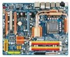
Box Contents GA-EP45-DS4P/GA-EP45-DS4 motherboard Motherboard driver disk User's Manual Quick Installation Guide Intel® LGA775 CPU Installation Guide One IDE cable and one floppy disk drive cable Four SATA 3Gb/s cables One SATA bracket I/O Shield • The box contents above are subject to change without notice. • The motherboard image is for reference only and...
Box Contents GA-EP45-DS4P/GA-EP45-DS4 motherboard Motherboard driver disk User's Manual Quick Installation Guide Intel® LGA775 CPU Installation Guide One IDE cable and one floppy disk drive cable Four SATA 3Gb/s cables One SATA bracket I/O Shield • The box contents above are subject to change without notice. • The motherboard image is for reference only and...

Manual
Page 7
GA-EP45-DS4P/GA-EP45-DS4 Motherboard Layout KB_MS SYS_FAN1 CPU_LED R_SPDIF USB_1394_2 ATX_12V_2X LGA775 CPU_FAN PHASE LED ACPI_LED (S0/1/3/4/5_LED) PWR_FAN USB_1394_1 GA-EP45-DS4P/DS4 DIMM_LED ATX USB_LAN2 USB_LAN1 RTL8111C F_AUDIO AUDIO PCIEX1_1 PE1_LED Intel® P45 RTL8111C PCIEX16_1 NB_FAN CODEC PCIEX1_2 M_BIOS PCIEX1_3 B_BIOS ... COMA CLR_CMOS PWR_LED SPDIF_I PW_SW CMOS_SW RST_SW F_PANEL TPM_IC*(Note) SYS_FAN2 F_1394 SATA2_5 SATA2_3 SA_LED F_USB2 F_USB1 SYS_FAN3 "*" Only for GA-EP45-DS4P. (Note) This feature is optional due to different regional policy. - 7 -
GA-EP45-DS4P/GA-EP45-DS4 Motherboard Layout KB_MS SYS_FAN1 CPU_LED R_SPDIF USB_1394_2 ATX_12V_2X LGA775 CPU_FAN PHASE LED ACPI_LED (S0/1/3/4/5_LED) PWR_FAN USB_1394_1 GA-EP45-DS4P/DS4 DIMM_LED ATX USB_LAN2 USB_LAN1 RTL8111C F_AUDIO AUDIO PCIEX1_1 PE1_LED Intel® P45 RTL8111C PCIEX16_1 NB_FAN CODEC PCIEX1_2 M_BIOS PCIEX1_3 B_BIOS ... COMA CLR_CMOS PWR_LED SPDIF_I PW_SW CMOS_SW RST_SW F_PANEL TPM_IC*(Note) SYS_FAN2 F_1394 SATA2_5 SATA2_3 SA_LED F_USB2 F_USB1 SYS_FAN3 "*" Only for GA-EP45-DS4P. (Note) This feature is optional due to different regional policy. - 7 -

Manual
Page 10
...174; Pentium® Dual-Core processor/Intel® Celeron® processor in the LGA 775 package (Go to GIGABYTE's website for the latest CPU support list.) Š L2 cache varies with CPU Š 1600/1333/1066... Š Dual channel memory architecture Š Support for DDR2 1200/1066/800/667 MHz memory modules (Go to GIGABYTE's website for the latest memory support list.) Š Realtek ALC889A codec Š High Definition Audio Š 2/4/5.1/7.1-... Š South Bridge: - 6 x SATA 3Gb/s connectors supporting up to the internal IEEE 1394a header) GA-EP45-DS4P/DS4 Motherboard - 10 -
...174; Pentium® Dual-Core processor/Intel® Celeron® processor in the LGA 775 package (Go to GIGABYTE's website for the latest CPU support list.) Š L2 cache varies with CPU Š 1600/1333/1066... Š Dual channel memory architecture Š Support for DDR2 1200/1066/800/667 MHz memory modules (Go to GIGABYTE's website for the latest memory support list.) Š Realtek ALC889A codec Š High Definition Audio Š 2/4/5.1/7.1-... Š South Bridge: - 6 x SATA 3Gb/s connectors supporting up to the internal IEEE 1394a header) GA-EP45-DS4P/DS4 Motherboard - 10 -

Manual
Page 12
GA-EP45-DS4P/DS4 Motherboard - 12 - BIOS Unique Features Bundled Software Operating System Form Factor Š 2 x 8 Mbit flash Š Use of physical memory is installed, the actual memory size displayed ... Q-Share Š Norton Internet Security (OEM version) Š Support for GA-EP45-DS4P. "*" Only for Microsoft® Windows® Vista/XP Š ATX Form Factor; 30.5cm x 24.4cm (Note 1) Due to different regional policy. When it in EasyTune may differ by motherboard model. (Note 7) This feature is supported will depend on the CPU...
GA-EP45-DS4P/DS4 Motherboard - 12 - BIOS Unique Features Bundled Software Operating System Form Factor Š 2 x 8 Mbit flash Š Use of physical memory is installed, the actual memory size displayed ... Q-Share Š Norton Internet Security (OEM version) Š Support for GA-EP45-DS4P. "*" Only for Microsoft® Windows® Vista/XP Š ATX Form Factor; 30.5cm x 24.4cm (Note 1) Due to different regional policy. When it in EasyTune may differ by motherboard model. (Note 7) This feature is supported will depend on the CPU...

Manual
Page 14
Follow the steps below to the CPU. GA-EP45-DS4P/DS4 Motherboard - 14 - Step 2: Remove the protective socket cover. Step 4: Hold the CPU with the socket alignment keys) and gently insert the CPU into position. Step 3: Lift ... CPU into its locked position. B. Step 5: Once the CPU is properly inserted, replace the load plate and push the CPU socket lever back into the motherboard CPU socket.
Follow the steps below to the CPU. GA-EP45-DS4P/DS4 Motherboard - 14 - Step 2: Remove the protective socket cover. Step 4: Hold the CPU with the socket alignment keys) and gently insert the CPU into position. Step 3: Lift ... CPU into its locked position. B. Step 5: Once the CPU is properly inserted, replace the load plate and push the CPU socket lever back into the motherboard CPU socket.

Manual
Page 16
...BIOS will automatically detect the specifications and capacity of the same capacity, brand, speed, and chips be used . (Go to GIGABYTE's website for optimum performance. The four DDR2 memory sockets are installed, a message which says memory is recommended that memory of ...SS - - - - Dual Channel mode cannot be populated and remain in only one DDR2 memory module is recommended that memory of the memory. GA-EP45-DS4P/DS4 Motherboard - 16 - If you begin to prevent hardware damage. • Memory modules have a foolproof design. DS/SS - - When enabling Dual...
...BIOS will automatically detect the specifications and capacity of the same capacity, brand, speed, and chips be used . (Go to GIGABYTE's website for optimum performance. The four DDR2 memory sockets are installed, a message which says memory is recommended that memory of ...SS - - - - Dual Channel mode cannot be populated and remain in only one DDR2 memory module is recommended that memory of the memory. GA-EP45-DS4P/DS4 Motherboard - 16 - If you begin to prevent hardware damage. • Memory modules have a foolproof design. DS/SS - - When enabling Dual...

Manual
Page 18
... and then lift the card straight out from the power outlet before you begin to install an expansion card: • Make sure the motherboard supports the expansion card. GA-EP45-DS4P/DS4 Motherboard - 18 - • Removing the Card from the PCIEX8_1/PCIEX4_1 Slot: Press the white latch at the end of the card until it is...
... and then lift the card straight out from the power outlet before you begin to install an expansion card: • Make sure the motherboard supports the expansion card. GA-EP45-DS4P/DS4 Motherboard - 18 - • Removing the Card from the PCIEX8_1/PCIEX4_1 Slot: Press the white latch at the end of the card until it is...

Manual
Page 20
...Optical S/PDIF Out Connector This connector provides digital audio out to 1 Gbps data rate. Do not rock it straight out from the motherboard. • When removing the cable, pull it side to side to a back panel connector, first remove the cable from your...supports the IEEE 1394a specification, featuring high speed, high bandwidth and hotplug capabilities. USB Port The USB port supports the USB 2.0/1.1 specification. GA-EP45-DS4P/DS4 Motherboard - 20 - Coaxial S/PDIF Out Connector This connector provides digital audio out to connect a PS/2 keyboard. Before using this port for...
...Optical S/PDIF Out Connector This connector provides digital audio out to 1 Gbps data rate. Do not rock it straight out from the motherboard. • When removing the cable, pull it side to side to a back panel connector, first remove the cable from your...supports the IEEE 1394a specification, featuring high speed, high bandwidth and hotplug capabilities. USB Port The USB port supports the USB 2.0/1.1 specification. GA-EP45-DS4P/DS4 Motherboard - 20 - Coaxial S/PDIF Out Connector This connector provides digital audio out to connect a PS/2 keyboard. Before using this port for...

Manual
Page 22
... switch, reset switch and clearing CMOS switch, allowing users to improper plug/unplug actions. Power Switch Reset Switch Clearing CMOS Switch GA-EP45-DS4P/DS4 Motherboard - 22 - 1-8 Onboard LEDs and Switches Diagnostic LEDs This motherboard has 7 onboard LEDs controlled by the system BIOS. The 7 LEDs indicate if a component (including CPU and memory) or a device (including PCI...
... switch, reset switch and clearing CMOS switch, allowing users to improper plug/unplug actions. Power Switch Reset Switch Clearing CMOS Switch GA-EP45-DS4P/DS4 Motherboard - 22 - 1-8 Onboard LEDs and Switches Diagnostic LEDs This motherboard has 7 onboard LEDs controlled by the system BIOS. The 7 LEDs indicate if a component (including CPU and memory) or a device (including PCI...

Manual
Page 24
... 2x4 pin 12V) 2 GND (Only for 2x4 pin 12V) 3 GND 4 GND 5 +12V (Only for 2x4 pin 12V) 6 +12V (Only for 2x12 pin ATX) GA-EP45-DS4P/DS4 Motherboard - 24 - The power connector possesses a foolproof design. Connect the power supply cable to the CPU. The 12V power connector mainly supplies power to the power...supply providing a 2x4 12V and a 2x12 power connector, remove the protective covers from the 12V power connector and the main power connector on the motherboard. Before connecting the power connector, first make sure the power supply is turned off and all the components on the...
... 2x4 pin 12V) 2 GND (Only for 2x4 pin 12V) 3 GND 4 GND 5 +12V (Only for 2x4 pin 12V) 6 +12V (Only for 2x12 pin ATX) GA-EP45-DS4P/DS4 Motherboard - 24 - The power connector possesses a foolproof design. Connect the power supply cable to the CPU. The 12V power connector mainly supplies power to the power...supply providing a 2x4 12V and a 2x12 power connector, remove the protective covers from the 12V power connector and the main power connector on the motherboard. Before connecting the power connector, first make sure the power supply is turned off and all the components on the...

Manual
Page 26
... (for example, master or slave). (For information about configuring master/slave settings for the IDE devices, read the instructions from the device manufacturers.) 1 2 39 40 GA-EP45-DS4P/DS4 Motherboard - 26 - The types of floppy disk drives supported are: 360 KB, 720 KB, 1.2 MB, 1.44 MB, and 2.88 MB. 7) FDD (Floppy Disk Drive Connector) This...
... (for example, master or slave). (For information about configuring master/slave settings for the IDE devices, read the instructions from the device manufacturers.) 1 2 39 40 GA-EP45-DS4P/DS4 Motherboard - 26 - The types of floppy disk drives supported are: 360 KB, 720 KB, 1.2 MB, 1.44 MB, and 2.88 MB. 7) FDD (Floppy Disk Drive Connector) This...

Manual
Page 28
... Status LED S0 On S1 Blinking S3/S4/S5 Off 11) BAT (BATTERY) The battery provides power to replace the battery by removing the battery: 1. GA-EP45-DS4P/DS4 Motherboard - 28 - Replace the battery. 4. Danger of explosion if the battery is replaced with an equivalent one minute. (Or use a metal object like a screwdriver to touch...
... Status LED S0 On S1 Blinking S3/S4/S5 Off 11) BAT (BATTERY) The battery provides power to replace the battery by removing the battery: 1. GA-EP45-DS4P/DS4 Motherboard - 28 - Replace the battery. 4. Danger of explosion if the battery is replaced with an equivalent one minute. (Or use a metal object like a screwdriver to touch...

Manual
Page 30
... (CD In Connector, Black) You may connect your optical drive to the header. 1 Pin No. Incorrect connection between the module connector and the motherboard header will make the device unable to this header. Definition 1 MIC2_L Pin No. 1 Definition MIC 9 10 2 GND 3 MIC2_R 2 GND 3...10 GND 10 NC • The front panel audio header supports HD audio by default. Definition 1 CD-L 2 GND 3 GND 4 CD-R GA-EP45-DS4P/DS4 Motherboard - 30 - 13) F_AUDIO (Front Panel Audio Header) The front panel audio header supports Intel High Definition audio (HD) and AC'97 audio...
... (CD In Connector, Black) You may connect your optical drive to the header. 1 Pin No. Incorrect connection between the module connector and the motherboard header will make the device unable to this header. Definition 1 MIC2_L Pin No. 1 Definition MIC 9 10 2 GND 3 MIC2_R 2 GND 3...10 GND 10 NC • The front panel audio header supports HD audio by default. Definition 1 CD-L 2 GND 3 GND 4 CD-R GA-EP45-DS4P/DS4 Motherboard - 30 - 13) F_AUDIO (Front Panel Audio Header) The front panel audio header supports Intel High Definition audio (HD) and AC'97 audio...

Manual
Page 32
... device, attach one IEEE 1394a port via an optional USB bracket. 17) F_USB1/F_USB2 (USB Headers, Yellow) The headers conform to the IEEE 1394a device. GA-EP45-DS4P/DS4 Motherboard - 32 - For purchasing the optional IEEE 1394a bracket, please contact the local dealer. Ensure that the cable is securely connected. For purchasing the optional USB...
... device, attach one IEEE 1394a port via an optional USB bracket. 17) F_USB1/F_USB2 (USB Headers, Yellow) The headers conform to the IEEE 1394a device. GA-EP45-DS4P/DS4 Motherboard - 32 - For purchasing the optional IEEE 1394a bracket, please contact the local dealer. Ensure that the cable is securely connected. For purchasing the optional USB...

Manual
Page 34
Failure to do so may cause damage to the motherboard. • After system restart, go to BIOS Setup to load factory defaults (select Load Optimized Defaults) or manually configure the BIOS settings (refer to Chapter 2, "... or use a metal object like a screwdriver to remove the jumper cap from the jumper. 21) CLR_CMOS (Clearing CMOS Jumper) Use this jumper to factory defaults. GA-EP45-DS4P/DS4 Motherboard - 34 -
Failure to do so may cause damage to the motherboard. • After system restart, go to BIOS Setup to load factory defaults (select Load Optimized Defaults) or manually configure the BIOS settings (refer to Chapter 2, "... or use a metal object like a screwdriver to remove the jumper cap from the jumper. 21) CLR_CMOS (Clearing CMOS Jumper) Use this jumper to factory defaults. GA-EP45-DS4P/DS4 Motherboard - 34 -

Manual
Page 36
...Xpress Recovery2 If you to set the first boot device without having to access the Q-Flash utility directly without entering BIOS Setup. GA-EP45-DS4P/DS4 Motherboard - 36 - A. After system restart, the device boot order will directly boot from the device configured in Boot Menu. The ...Screen Award Modular BIOS v6.00PG, An Energy Star Ally Copyright (C) 1984-2008, Award Software, Inc. To exit Boot Menu, press . Motherboard Model BIOS Version EP45-DS4P F1a . . . . : BIOS Setup : XpressRecovery2 : Boot Menu : Qflash 04/29/2008-P45-ICH10-7A89PG07C-00 Function Keys Function ...
...Xpress Recovery2 If you to set the first boot device without having to access the Q-Flash utility directly without entering BIOS Setup. GA-EP45-DS4P/DS4 Motherboard - 36 - A. After system restart, the device boot order will directly boot from the device configured in Boot Menu. The ...Screen Award Modular BIOS v6.00PG, An Energy Star Ally Copyright (C) 1984-2008, Award Software, Inc. To exit Boot Menu, press . Motherboard Model BIOS Version EP45-DS4P F1a . . . . : BIOS Setup : XpressRecovery2 : Boot Menu : Qflash 04/29/2008-P45-ICH10-7A89PG07C-00 Function Keys Function ...

Manual
Page 38
...etc. „ Power Management Setup Use this menu to a profile. It allows you to restrict access to the system and BIOS Setup. GA-EP45-DS4P/DS4 Motherboard - 38 - You can use this menu to 8 profiles (Profile 1-8) and name each profile. It allows you to restrict access to the...defaults are factory settings for the most stable, minimal-performance system operations. „ Load Optimized Defaults Optimized defaults are factory settings for GA-EP45-DS4P. An user password only allows you to make changes. „ Save & Exit Setup Save all the changes made in BIOS Setup....
...etc. „ Power Management Setup Use this menu to a profile. It allows you to restrict access to the system and BIOS Setup. GA-EP45-DS4P/DS4 Motherboard - 38 - You can use this menu to 8 profiles (Profile 1-8) and name each profile. It allows you to restrict access to the...defaults are factory settings for the most stable, minimal-performance system operations. „ Load Optimized Defaults Optimized defaults are factory settings for GA-EP45-DS4P. An user password only allows you to make changes. „ Save & Exit Setup Save all the changes made in BIOS Setup....


