
Manual
Page 1
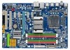
GA-EP43T-UD3L LGA775 socket motherboard for Intel® Core™ processor family/ Intel® Pentium® processor family/Intel® Celeron® processor family User's Manual Rev. 1101 12ME-43TUD3L-1101R
GA-EP43T-UD3L LGA775 socket motherboard for Intel® Core™ processor family/ Intel® Pentium® processor family/Intel® Celeron® processor family User's Manual Rev. 1101 12ME-43TUD3L-1101R
Manual
Page 2
Motherboard GA-EP43T-UD3L Apr. 30, 2009 Motherboard GA-EP43T-UD3L Apr. 30, 2009
Motherboard GA-EP43T-UD3L Apr. 30, 2009 Motherboard GA-EP43T-UD3L Apr. 30, 2009
Manual
Page 3
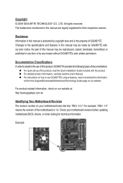
...assist in this : "REV: X.X." For product-related information, check on our website at: http://www.gigabyte.com.tw Identifying Your Motherboard Revision The revision number on our website. Example: Documentation Classifications In order to their respective owners. The trademarks...laws and is the property of the motherboard is protected by GIGABYTE without GIGABYTE's prior written permission. Disclaimer Information in this manual may be reproduced, copied, translated, transmitted, or published in this product, GIGABYTE provides the following types of documentations: For...
...assist in this : "REV: X.X." For product-related information, check on our website at: http://www.gigabyte.com.tw Identifying Your Motherboard Revision The revision number on our website. Example: Documentation Classifications In order to their respective owners. The trademarks...laws and is the property of the motherboard is protected by GIGABYTE without GIGABYTE's prior written permission. Disclaimer Information in this manual may be reproduced, copied, translated, transmitted, or published in this product, GIGABYTE provides the following types of documentations: For...
Manual
Page 4
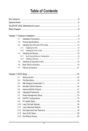
Table of Contents Box Contents...6 Optional Items...6 GA-EP43T-UD3L Motherboard Layout 7 Block Diagram...8 Chapter 1 Hardware Installation 9 1-1 Installation Precautions 9 1-2 Product Specifications 10 1-3 Installing the CPU and CPU Cooler 13 1-3-1 Installing the CPU 13 1-3-2 Installing the CPU ...
Table of Contents Box Contents...6 Optional Items...6 GA-EP43T-UD3L Motherboard Layout 7 Block Diagram...8 Chapter 1 Hardware Installation 9 1-1 Installation Precautions 9 1-2 Product Specifications 10 1-3 Installing the CPU and CPU Cooler 13 1-3-1 Installing the CPU 13 1-3-2 Installing the CPU ...
Manual
Page 6
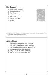
.... 12CR1-1SPDIN-0*R) COM port cable (Part No. 12CF1-1CM001-3*R) LPT port cable (Part No. 12CF1-1LP001-0*R) - 6 - The box contents are for reference only. Box Contents GA-EP43T-UD3L motherboard Motherboard driver disk User's Manual Quick Installation Guide One IDE cable Two SATA 3Gb/s cables I/O Shield • The box contents above are subject to change without...
.... 12CR1-1SPDIN-0*R) COM port cable (Part No. 12CF1-1CM001-3*R) LPT port cable (Part No. 12CF1-1LP001-0*R) - 6 - The box contents are for reference only. Box Contents GA-EP43T-UD3L motherboard Motherboard driver disk User's Manual Quick Installation Guide One IDE cable Two SATA 3Gb/s cables I/O Shield • The box contents above are subject to change without...
Manual
Page 7
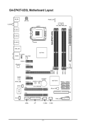
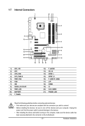
GA-EP43T-UD3L Motherboard Layout KB_MS R_SPDIF R_USB_1 ATX_12V LGA775 PHASE_LED CPU_FAN PWR_FAN ATX GA-EP43T-UD3L R_USB_2 R_USB_3 USB_LAN F_AUDIO AUDIO SYS_FAN1 PCIEX1_1 RTL8111C PCIEX1_2 PCIEX16 Intel® P43 FDD SYS_FAN2 DDR3_1 DDR3_2 DDR3_3 DDR3_4 CODEC SPDIF_O SPDIF_I CD_IN IT8718 PCIEX1_3 PCIEX1_4 BATTERY M_BIOS B_BIOS CLR_CMOS PCI1 Intel® ICH10 JMicron 368 SATA2_3 SATA2_0 SATA2_4 SATA2_1 SATA2_5 SATA2_2 PCI2 IDE F_PANEL PWR_LED CI COMA LPT F_USB2 F_USB1 - 7 -
GA-EP43T-UD3L Motherboard Layout KB_MS R_SPDIF R_USB_1 ATX_12V LGA775 PHASE_LED CPU_FAN PWR_FAN ATX GA-EP43T-UD3L R_USB_2 R_USB_3 USB_LAN F_AUDIO AUDIO SYS_FAN1 PCIEX1_1 RTL8111C PCIEX1_2 PCIEX16 Intel® P43 FDD SYS_FAN2 DDR3_1 DDR3_2 DDR3_3 DDR3_4 CODEC SPDIF_O SPDIF_I CD_IN IT8718 PCIEX1_3 PCIEX1_4 BATTERY M_BIOS B_BIOS CLR_CMOS PCI1 Intel® ICH10 JMicron 368 SATA2_3 SATA2_0 SATA2_4 SATA2_1 SATA2_5 SATA2_2 PCI2 IDE F_PANEL PWR_LED CI COMA LPT F_USB2 F_USB1 - 7 -

Manual
Page 9
...8226; Before using the product, please verify that all cables and power connectors of your dealer. Chapter 1 Hardware Installation 1-1 Installation Precautions The motherboard contains numerous delicate electronic circuits and components which can lead to damage to system components as well as physical harm to the user. •...an ESD wrist strap, keep your hands dry and first touch a metal object to eliminate static electricity. • Prior to installing the motherboard, please have it on top of an antistatic pad or within the computer casing. • Do not place the computer system on ...
...8226; Before using the product, please verify that all cables and power connectors of your dealer. Chapter 1 Hardware Installation 1-1 Installation Precautions The motherboard contains numerous delicate electronic circuits and components which can lead to damage to system components as well as physical harm to the user. •...an ESD wrist strap, keep your hands dry and first touch a metal object to eliminate static electricity. • Prior to installing the motherboard, please have it on top of an antistatic pad or within the computer casing. • Do not place the computer system on ...
Manual
Page 10
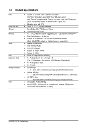
... Duo processor/ Intel® Pentium® processor/Intel® Celeron® processor in the LGA775 package (Go to GIGABYTE's website for the latest CPU support list.) L2 cache varies with CPU 1600(O.C.)/1333/1066/800 MHz FSB North Bridge:...memory (Note 1) Dual channel memory architecture Support for DDR3 1600/1333/1066/800 MHz memory modules (Go to GIGABYTE's website for the latest memory support list.) Realtek ALC888 codec High Definition Audio 2/4/5.1/7.1-channel Support for S/PDIF In...back panel, 4 via the USB brackets connected to the internal USB headers) GA-EP43T-UD3L Motherboard - 10 -
... Duo processor/ Intel® Pentium® processor/Intel® Celeron® processor in the LGA775 package (Go to GIGABYTE's website for the latest CPU support list.) L2 cache varies with CPU 1600(O.C.)/1333/1066/800 MHz FSB North Bridge:...memory (Note 1) Dual channel memory architecture Support for DDR3 1600/1333/1066/800 MHz memory modules (Go to GIGABYTE's website for the latest memory support list.) Realtek ALC888 codec High Definition Audio 2/4/5.1/7.1-channel Support for S/PDIF In...back panel, 4 via the USB brackets connected to the internal USB headers) GA-EP43T-UD3L Motherboard - 10 -
Manual
Page 12
... CPU/system fan speed control function is supported will depend on the CPU/system cooler you install. (Note 3) Available functions in EasyTune may differ by motherboard model. GA-EP43T-UD3L Motherboard - 12 -
... CPU/system fan speed control function is supported will depend on the CPU/system cooler you install. (Note 3) Available functions in EasyTune may differ by motherboard model. GA-EP43T-UD3L Motherboard - 12 -
Manual
Page 13
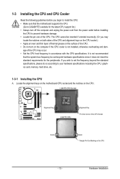
...oriented incorrectly. (Or you may occur. • Set the CPU host frequency in accordance with the CPU specifications. Locate the alignment keys on the motherboard CPU socket and the notches on the CPU - 13 - If you wish to set beyond the standard specifications, please do so according to your ... for the latest CPU support list.) • Always turn on the computer if the CPU cooler is not recommended that the motherboard supports the CPU. (Go to GIGABYTE's website for the peripherals. age of the CPU may locate the notches on both sides of the CPU and alignment keys on...
...oriented incorrectly. (Or you may occur. • Set the CPU host frequency in accordance with the CPU specifications. Locate the alignment keys on the motherboard CPU socket and the notches on the CPU - 13 - If you wish to set beyond the standard specifications, please do so according to your ... for the latest CPU support list.) • Always turn on the computer if the CPU cooler is not recommended that the motherboard supports the CPU. (Go to GIGABYTE's website for the peripherals. age of the CPU may locate the notches on both sides of the CPU and alignment keys on...
Manual
Page 14
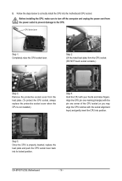
... the protective socket cover when the CPU is properly inserted, replace the load plate and push the CPU socket lever back into its locked position. GA-EP43T-UD3L Motherboard - 14 - Follow the steps below to the CPU. B. Step 5: Once the CPU is not installed.) Step 4: Hold the CPU with the socket alignment keys) and...
... the protective socket cover when the CPU is properly inserted, replace the load plate and push the CPU socket lever back into its locked position. GA-EP43T-UD3L Motherboard - 14 - Follow the steps below to the CPU. B. Step 5: Once the CPU is not installed.) Step 4: Hold the CPU with the socket alignment keys) and...
Manual
Page 15
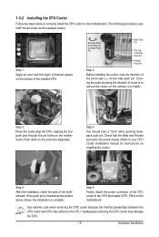
...the back of the installed CPU. Hardware Installation 1-3-2 Installing the CPU Cooler Follow the steps below to correctly install the CPU cooler on the motherboard. (The following procedure uses Intel® boxed cooler as the picture above shows, the installation is complete. Use extreme care when removing the ..., attach the power connector of arrow is to remove the cooler, on the contrary, is to the CPU fan header (CPU_FAN) on the motherboard. Direction of the Arrow Sign on the Male Push Pin Male Push Pin The Top of Female Push Pin Female Push Pin Step 2: Before ...
...the back of the installed CPU. Hardware Installation 1-3-2 Installing the CPU Cooler Follow the steps below to correctly install the CPU cooler on the motherboard. (The following procedure uses Intel® boxed cooler as the picture above shows, the installation is complete. Use extreme care when removing the ..., attach the power connector of arrow is to remove the cooler, on the contrary, is to the CPU fan header (CPU_FAN) on the motherboard. Direction of the Arrow Sign on the Male Push Pin Male Push Pin The Top of Female Push Pin Female Push Pin Step 2: Before ...
Manual
Page 16
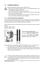
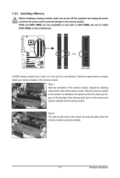
... the computer and unplug the power cord from the power outlet before installing the memory to prevent hardware damage. • Memory modules have a foolproof design. GA-EP43T-UD3L Motherboard - 16 - When enabling Dual Channel mode with two or four memory modules, it is recommended that memory of the memory. 1-4 Installing the Memory Read the... says memory is operating in Dual Channel mode/performance. DS/SS - - Enabling Dual Channel memory mode will appear during the POST. If you begin to GIGABYTE's website for optimum performance. DS/SS - - - -
... the computer and unplug the power cord from the power outlet before installing the memory to prevent hardware damage. • Memory modules have a foolproof design. GA-EP43T-UD3L Motherboard - 16 - When enabling Dual Channel mode with two or four memory modules, it is recommended that memory of the memory. 1-4 Installing the Memory Read the... says memory is operating in Dual Channel mode/performance. DS/SS - - Enabling Dual Channel memory mode will appear during the POST. If you begin to GIGABYTE's website for optimum performance. DS/SS - - - -
Manual
Page 17
... the top edge of the socket will snap into the memory socket. Step 2: The clips at both ends of the memory, push down on this motherboard. Hardware Installation DDR3 and DDR2 DIMMs are not compatible to each other or DDR DIMMs. Be sure to correctly install your fingers on the socket...
... the top edge of the socket will snap into the memory socket. Step 2: The clips at both ends of the memory, push down on this motherboard. Hardware Installation DDR3 and DDR2 DIMMs are not compatible to each other or DDR DIMMs. Be sure to correctly install your fingers on the socket...
Manual
Page 18
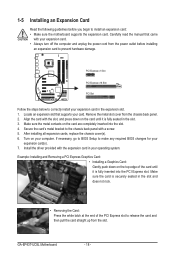
...the end of the card until it is fully inserted into the slot. 4. If necessary, go to BIOS Setup to prevent hardware damage. GA-EP43T-UD3L Motherboard - 18 - Align the card with a screw. 5. Carefully read the manual that supports your expansion card in the slot. 3. PCI ... the metal contacts on your operating system. Secure the card's metal bracket to install an expansion card: • Make sure the motherboard supports the expansion card. 1-5 Installing an Expansion Card Read the following guidelines before installing an expansion card to make any required BIOS ...
...the end of the card until it is fully inserted into the slot. 4. If necessary, go to BIOS Setup to prevent hardware damage. GA-EP43T-UD3L Motherboard - 18 - Align the card with a screw. 5. Carefully read the manual that supports your expansion card in the slot. 3. PCI ... the metal contacts on your operating system. Secure the card's metal bracket to install an expansion card: • Make sure the motherboard supports the expansion card. 1-5 Installing an Expansion Card Read the following guidelines before installing an expansion card to make any required BIOS ...
Manual
Page 19
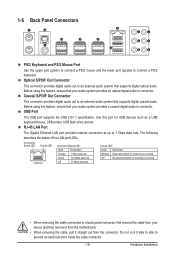
... Port The Gigabit Ethernet LAN port provides Internet connection at up to an external audio system that your device and then remove it from the motherboard. • When removing the cable, pull it straight out from your audio system provides an optical digital audio in connector. The following describes the states...
... Port The Gigabit Ethernet LAN port provides Internet connection at up to an external audio system that your device and then remove it from the motherboard. • When removing the cable, pull it straight out from your audio system provides an optical digital audio in connector. The following describes the states...
Manual
Page 20
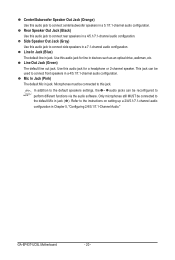
... in jack. Only microphones still MUST be connected to this audio jack to connect rear speakers in devices such as an optical drive, walkman, etc. GA-EP43T-UD3L Motherboard - 20 - Use this audio jack to connect side speakers in a 5.1/7.1-channel audio configuration. Rear Speaker Out Jack (Black) Use this audio jack for a headphone or...
... in jack. Only microphones still MUST be connected to this audio jack to connect rear speakers in devices such as an optical drive, walkman, etc. GA-EP43T-UD3L Motherboard - 20 - Use this audio jack to connect side speakers in a 5.1/7.1-channel audio configuration. Rear Speaker Out Jack (Black) Use this audio jack for a headphone or...
Manual
Page 21
... 14) SPDIF_I 15) SPDIF_O 16) F_USB1/F_USB2 17) LPT 18) COMA 19) CI 20) CLR_CMOS 21) PHASE_LED Read the following guidelines before turning on the motherboard. - 21 -
... 14) SPDIF_I 15) SPDIF_O 16) F_USB1/F_USB2 17) LPT 18) COMA 19) CI 20) CLR_CMOS 21) PHASE_LED Read the following guidelines before turning on the motherboard. - 21 -
Manual
Page 22
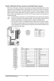
... power supply cable into pins under the protective cover when using a 2x12 power supply, remove the protective cover from the main power connector on the motherboard. The power connector possesses a foolproof design. If a power supply is used that does not provide the required power, the result can lead to an unstable... 3.3V -12V GND PS_ON (soft On/Off) GND GND GND -5V +5V +5V +5V (Only for 2x12-pin ATX) GND (Only for 2x12-pin ATX) GA-EP43T-UD3L Motherboard - 22 - Before connecting the power connector, first make sure the power supply is turned off and all the components on the...
... power supply cable into pins under the protective cover when using a 2x12 power supply, remove the protective cover from the main power connector on the motherboard. The power connector possesses a foolproof design. If a power supply is used that does not provide the required power, the result can lead to an unstable... 3.3V -12V GND PS_ON (soft On/Off) GND GND GND -5V +5V +5V +5V (Only for 2x12-pin ATX) GND (Only for 2x12-pin ATX) GA-EP43T-UD3L Motherboard - 22 - Before connecting the power connector, first make sure the power supply is turned off and all the components on the...
Manual
Page 23
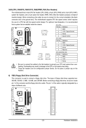
... is typically designated by a stripe of the connector and the floppy disk drive cable. 3/4/5) CPU_FAN/SYS_FAN1/SYS_FAN2/PWR_FAN (Fan Headers) The motherboard has a 4-pin CPU fan header (CPU_FAN), a 4-pin (SYS_FAN2) and a 3-pin (SYS_FAN1) system fan headers, and a 3-pin power fan header (PWR_FAN). The... motherboard supports CPU fan speed control, which requires the use of the cable is used to prevent your CPU and system from overheating. Most fan headers ...
... is typically designated by a stripe of the connector and the floppy disk drive cable. 3/4/5) CPU_FAN/SYS_FAN1/SYS_FAN2/PWR_FAN (Fan Headers) The motherboard has a 4-pin CPU fan header (CPU_FAN), a 4-pin (SYS_FAN2) and a 3-pin (SYS_FAN1) system fan headers, and a 3-pin power fan header (PWR_FAN). The... motherboard supports CPU fan speed control, which requires the use of the cable is used to prevent your CPU and system from overheating. Most fan headers ...


