Manual
Page 1
GA-EP43-DS3R/ GA-EP43-DS3 LGA775 socket motherboard for Intel® CoreTM processor family/ Intel® Pentium® processor family/Intel® Celeron® processor family User's Manual Rev. 1004 12ME-EP43DS3R-1004R
GA-EP43-DS3R/ GA-EP43-DS3 LGA775 socket motherboard for Intel® CoreTM processor family/ Intel® Pentium® processor family/Intel® Celeron® processor family User's Manual Rev. 1004 12ME-EP43DS3R-1004R
Manual
Page 2
Motherboard GA-EP43-DS3R/GA-EP43-DS3 May 15, 2008 Motherboard GA-EP43-DS3R/ GA-EP43-DS3 May 15, 2008
Motherboard GA-EP43-DS3R/GA-EP43-DS3 May 15, 2008 Motherboard GA-EP43-DS3R/ GA-EP43-DS3 May 15, 2008
Manual
Page 3
...the User's Manual. „ For instructions on how to GIGABYTE UNITED INC. Documentation Classifications In order to assist in this manual is protected by GIGABYTE without GIGABYTE's prior written permission. Check your motherboard looks like this manual may be reproduced, copied, translated,... registered to the specifications and features in the use GIGABYTE's unique features, read or download the information on/from the Support\Motherboard\Technology Guide page on your motherboard revision before updating motherboard BIOS, drivers, or when looking for technical information....
...the User's Manual. „ For instructions on how to GIGABYTE UNITED INC. Documentation Classifications In order to assist in this manual is protected by GIGABYTE without GIGABYTE's prior written permission. Check your motherboard looks like this manual may be reproduced, copied, translated,... registered to the specifications and features in the use GIGABYTE's unique features, read or download the information on/from the Support\Motherboard\Technology Guide page on your motherboard revision before updating motherboard BIOS, drivers, or when looking for technical information....
Manual
Page 4
Table of Contents Box Contents ...6 OptionalItems ...6 GA-EP43-DS3R/DS3 Motherboard Layout 7 Block Diagram ...8 Chapter 1 Hardware Installation 9 1-1 Installation Precautions 9 1-2 Product Specifications 10 1-3 Installing the CPU and CPU Cooler 13 1-3-1 Installing the CPU 13 1-3-2 Installing the CPU ... 60 2-12 Set Supervisor/User Password 61 2-13 Save & Exit Setup 62 2-14 Exit Without Saving 62 2-15 Security Chip Configuration (Note 63 Only for GA-EP43-DS3R. - 4 -
Table of Contents Box Contents ...6 OptionalItems ...6 GA-EP43-DS3R/DS3 Motherboard Layout 7 Block Diagram ...8 Chapter 1 Hardware Installation 9 1-1 Installation Precautions 9 1-2 Product Specifications 10 1-3 Installing the CPU and CPU Cooler 13 1-3-1 Installing the CPU 13 1-3-2 Installing the CPU ... 60 2-12 Set Supervisor/User Password 61 2-13 Save & Exit Setup 62 2-14 Exit Without Saving 62 2-15 Security Chip Configuration (Note 63 Only for GA-EP43-DS3R. - 4 -
Manual
Page 6
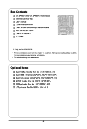
... cable (Part No. 12CR1-1SPDIN-01R) COM port cable (Part No. 12CF1-1CM001-32R) LPT port cable (Part No. 12CF1-1LP001-01R) - 6 - Box Contents GA-EP43-DS3R or GA-EP43-DS3 motherboard Motherboard driver disk User's Manual Quick Installation Guide One IDE cable and one floppy disk drive cable Four SATA 3Gb/s cables One SATA bracket I/O Shield...
... cable (Part No. 12CR1-1SPDIN-01R) COM port cable (Part No. 12CF1-1CM001-32R) LPT port cable (Part No. 12CF1-1LP001-01R) - 6 - Box Contents GA-EP43-DS3R or GA-EP43-DS3 motherboard Motherboard driver disk User's Manual Quick Installation Guide One IDE cable and one floppy disk drive cable Four SATA 3Gb/s cables One SATA bracket I/O Shield...
Manual
Page 7
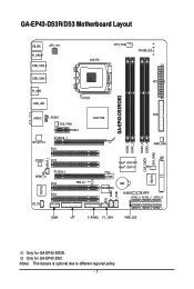
Only for GA-EP43-DS3R. GA-EP43-DS3R/DS3 Motherboard Layout KB_MS ATX_12V R_SPDIF USB_1394_2 LGA775 CPU_FAN PHASE LED USB_1394_1 ATX R_USB GA-EP43-DS3R/DS3 USB_LAN AUDIO F_AUDIO SYS_FAN1 PCIEX1 RTL8111C PCIEX16_1 PCI1 Intel® P43 FDD PWR_FAN DDR2_3 CLR_CMOS DDR2_4 SYS_FAN2 DDR2_1 DDR2_2 SPDIF_I CODEC PCI2 SPDIF_O ...IT8213 TPM IC (Note) TSB43AB23 CI F_USB2 F_USB1 BAT M_BIOS B_BIOS SATA2_4 SATA2_2 SATA2_0 SATA2_5 SATA2_3 SATA2_1 COMA LPT F_PANEL F1_1394 PWR_LED Only for GA-EP43-DS3. (Note) This feature is optional due to different regional policy. - 7 -
Only for GA-EP43-DS3R. GA-EP43-DS3R/DS3 Motherboard Layout KB_MS ATX_12V R_SPDIF USB_1394_2 LGA775 CPU_FAN PHASE LED USB_1394_1 ATX R_USB GA-EP43-DS3R/DS3 USB_LAN AUDIO F_AUDIO SYS_FAN1 PCIEX1 RTL8111C PCIEX16_1 PCI1 Intel® P43 FDD PWR_FAN DDR2_3 CLR_CMOS DDR2_4 SYS_FAN2 DDR2_1 DDR2_2 SPDIF_I CODEC PCI2 SPDIF_O ...IT8213 TPM IC (Note) TSB43AB23 CI F_USB2 F_USB1 BAT M_BIOS B_BIOS SATA2_4 SATA2_2 SATA2_0 SATA2_5 SATA2_3 SATA2_1 COMA LPT F_PANEL F1_1394 PWR_LED Only for GA-EP43-DS3. (Note) This feature is optional due to different regional policy. - 7 -

Manual
Page 9
... product, please consult a certified computer technician. - 9 - If you are connected tightly and securely. • When handling the motherboard, avoid touching any installation steps or have it on top of an antistatic pad or within an electrostatic shielding container. • Before... system in a high-temperature environment. • Turning on the computer power during the installation process can become damaged as a motherboard, CPU or memory. Hardware Installation These stickers are required for warranty validation. • Always remove the AC power by your hardware...
... product, please consult a certified computer technician. - 9 - If you are connected tightly and securely. • When handling the motherboard, avoid touching any installation steps or have it on top of an antistatic pad or within an electrostatic shielding container. • Before... system in a high-temperature environment. • Turning on the computer power during the installation process can become damaged as a motherboard, CPU or memory. Hardware Installation These stickers are required for warranty validation. • Always remove the AC power by your hardware...
Manual
Page 10
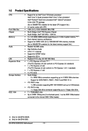
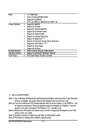
GA-EP43-DS3R/DS3 Motherboard - 10 - TSB43AB23 chip Š Up to 3 IEEE 1394a ports (2 on the back panel...Intel® Pentium® Dual-Core processor/Intel® Celeron® processor in the LGA 775 package (Go to GIGABYTE's website for the latest CPU support list.) Š L2 cache varies with CPU Š 1600 (O.C.)/1333/1066/800... 1) Š Dual channel memory architecture Š Support for DDR2 1200 (O.C.)/1066/800/667 MHz memory modules (Go to GIGABYTE's website for the latest memory support list.) Š Realtek ALC888 codec Š High Definition Audio Š 2/4/5.1/7.1-channel &#...
GA-EP43-DS3R/DS3 Motherboard - 10 - TSB43AB23 chip Š Up to 3 IEEE 1394a ports (2 on the back panel...Intel® Pentium® Dual-Core processor/Intel® Celeron® processor in the LGA 775 package (Go to GIGABYTE's website for the latest CPU support list.) Š L2 cache varies with CPU Š 1600 (O.C.)/1333/1066/800... 1) Š Dual channel memory architecture Š Support for DDR2 1200 (O.C.)/1066/800/667 MHz memory modules (Go to GIGABYTE's website for the latest memory support list.) Š Realtek ALC888 codec Š High Definition Audio Š 2/4/5.1/7.1-channel &#...
Manual
Page 12
... Security (OEM version) Š Support for Microsoft® Windows® Vista/XP Š ATX Form Factor; 30.5cm x 24.4cm Only for GA-EP43-DS3R. (Note 1) Due to Windows XP/Vista 32-bit operating system limitation, when more than 4 GB. (Note 2) If you are installing one ... you install. (Note 4) Available functions in EasyTune may differ by motherboard model. (Note 5) This feature is installed, the actual memory size displayed will be less than 4 GB of physical memory is optional due to install it in the PCIEX16_1 slot for optimum performance. GA-EP43-DS3R/DS3 Motherboard - 12 -
... Security (OEM version) Š Support for Microsoft® Windows® Vista/XP Š ATX Form Factor; 30.5cm x 24.4cm Only for GA-EP43-DS3R. (Note 1) Due to Windows XP/Vista 32-bit operating system limitation, when more than 4 GB. (Note 2) If you are installing one ... you install. (Note 4) Available functions in EasyTune may differ by motherboard model. (Note 5) This feature is installed, the actual memory size displayed will be less than 4 GB of physical memory is optional due to install it in the PCIEX16_1 slot for optimum performance. GA-EP43-DS3R/DS3 Motherboard - 12 -

Manual
Page 13
... do so according to your hardware specifications including the CPU, graphics card, memory, hard drive, etc. 1-3-1 Installing the CPU A. Locate the alignment keys on the motherboard CPU socket and the notches on the CPU - 13 - 1-3 Installing the CPU and CPU Cooler Read the following guidelines before installing the CPU to prevent... the standard requirements for the latest CPU support list.) • Always turn on the computer if the CPU cooler is not recom- mended that the motherboard supports the CPU. (Go to GIGABYTE's website for the peripherals.
... do so according to your hardware specifications including the CPU, graphics card, memory, hard drive, etc. 1-3-1 Installing the CPU A. Locate the alignment keys on the motherboard CPU socket and the notches on the CPU - 13 - 1-3 Installing the CPU and CPU Cooler Read the following guidelines before installing the CPU to prevent... the standard requirements for the latest CPU support list.) • Always turn on the computer if the CPU cooler is not recom- mended that the motherboard supports the CPU. (Go to GIGABYTE's website for the peripherals.
Manual
Page 14
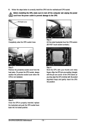
CPU Socket Lever Step 1: Completely raise the CPU socket lever. GA-EP43-DS3R/DS3 Motherboard - 14 - Step 2: Lift the metal load plate from the CPU socket. (DO NOT touch socket contacts.) Step 3: Remove the protective socket cover from the power ... you may align the CPU notches with your thumb and index fingers. Before installing the CPU, make sure to correctly install the CPU into the motherboard CPU socket. Step 5: Once the CPU is not installed.) Step 4: Hold the CPU with the socket alignment keys) and gently insert the CPU into its...
CPU Socket Lever Step 1: Completely raise the CPU socket lever. GA-EP43-DS3R/DS3 Motherboard - 14 - Step 2: Lift the metal load plate from the CPU socket. (DO NOT touch socket contacts.) Step 3: Remove the protective socket cover from the power ... you may align the CPU notches with your thumb and index fingers. Before installing the CPU, make sure to correctly install the CPU into the motherboard CPU socket. Step 5: Once the CPU is not installed.) Step 4: Hold the CPU with the socket alignment keys) and gently insert the CPU into its...
Manual
Page 15
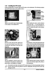
... 15 - Step 4: You should hear a "click" when pushing down on installing the cooler.) Step 5: After the installation, check the back of the motherboard. Step 6: Finally, attach the power connector of the CPU cooler to the CPU fan header (CPU_FAN) on the surface of the installed CPU. 1-3-2 Installing... the CPU Cooler Follow the steps below to correctly install the CPU cooler on the motherboard. (The following procedure uses Intel® boxed cooler as the picture above, the installation is to remove the cooler, on the contrary,...
... 15 - Step 4: You should hear a "click" when pushing down on installing the cooler.) Step 5: After the installation, check the back of the motherboard. Step 6: Finally, attach the power connector of the CPU cooler to the CPU fan header (CPU_FAN) on the surface of the installed CPU. 1-3-2 Installing... the CPU Cooler Follow the steps below to correctly install the CPU cooler on the motherboard. (The following procedure uses Intel® boxed cooler as the picture above, the installation is to remove the cooler, on the contrary,...
Manual
Page 16
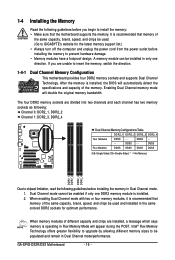
... (SS=Single-Sided, DS=Double-Sided, "- -"=No Memory) DDR2_1 DDR2_2 DDR2_3 DDR2_4 Due to GIGABYTE's website for optimum performance. Dual Channel mode cannot be enabled if only one direction. It is operating in Dual Channel mode. 1. GA-EP43-DS3R/DS3 Motherboard - 16 - A memory module can be used . (Go to chipset limitation, read the following guidelines...
... (SS=Single-Sided, DS=Double-Sided, "- -"=No Memory) DDR2_1 DDR2_2 DDR2_3 DDR2_4 Due to GIGABYTE's website for optimum performance. Dual Channel mode cannot be enabled if only one direction. It is operating in Dual Channel mode. 1. GA-EP43-DS3R/DS3 Motherboard - 16 - A memory module can be used . (Go to chipset limitation, read the following guidelines...

Manual
Page 17
... off the computer and unplug the power cord from the power outlet to prevent damage to the memory module. Place the memory module on this motherboard.
... off the computer and unplug the power cord from the power outlet to prevent damage to the memory module. Place the memory module on this motherboard.
Manual
Page 18
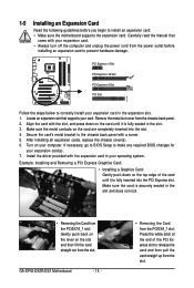
...Slot PCI Express x16 Slot PCI Express x4 Slot PCI Slot Follow the steps below to install an expansion card: • Make sure the motherboard supports the expansion card. Make sure the metal contacts on your computer. Turn on the card are completely inserted into the PCI Express slot... and then lift the card straight out from the power outlet before you begin to correctly install your expansion card in the expansion slot. 1. GA-EP43-DS3R/DS3 Motherboard - 18 - • Removing the Card from the PCIEX4_1 slot: Press the white latch at the end of the card until it is ...
...Slot PCI Express x16 Slot PCI Express x4 Slot PCI Slot Follow the steps below to install an expansion card: • Make sure the motherboard supports the expansion card. Make sure the metal contacts on your computer. Turn on the card are completely inserted into the PCI Express slot... and then lift the card straight out from the power outlet before you begin to correctly install your expansion card in the expansion slot. 1. GA-EP43-DS3R/DS3 Motherboard - 18 - • Removing the Card from the PCIEX4_1 slot: Press the white latch at the end of the card until it is ...

Manual
Page 19
... SATA bracket includes one SATA bracket, one SATA signal cable, and one end of the cable from the bracket to the power connector on your motherboard. Follow the steps below to install the SATA bracket: Step 1: Locate one free PCI slot and secure the SATA bracket to turn off your SATA...; Insert the SATA signal cable and SATA power cable securely into to the power supply. Connect the other ends of the external enclosure. Only for GA-EP43-DS3R. - 19 - Hardware Installation 1-6 Installing the SATA Bracket The SATA bracket allows you only need to connect the SATA signal cable.
... SATA bracket includes one SATA bracket, one SATA signal cable, and one end of the cable from the bracket to the power connector on your motherboard. Follow the steps below to install the SATA bracket: Step 1: Locate one free PCI slot and secure the SATA bracket to turn off your SATA...; Insert the SATA signal cable and SATA power cable securely into to the power supply. Connect the other ends of the external enclosure. Only for GA-EP43-DS3R. - 19 - Hardware Installation 1-6 Installing the SATA Bracket The SATA bracket allows you only need to connect the SATA signal cable.
Manual
Page 20
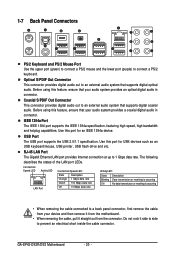
...printer, USB flash drive and etc. Do not rock it straight out from your audio system provides a coaxial digital audio in connector. GA-EP43-DS3R/DS3 Motherboard - 20 - The following describes the states of the LAN port LEDs. Before using this feature, ensure that your device and then ...remove it from the motherboard. • When removing the cable, pull it side to side to a back panel connector, first remove the cable from...
...printer, USB flash drive and etc. Do not rock it straight out from your audio system provides a coaxial digital audio in connector. GA-EP43-DS3R/DS3 Motherboard - 20 - The following describes the states of the LAN port LEDs. Before using this feature, ensure that your device and then ...remove it from the motherboard. • When removing the cable, pull it side to side to a back panel connector, first remove the cable from...
Manual
Page 22
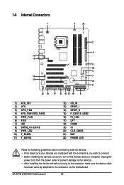
GA-EP43-DS3R/DS3 Motherboard - 22 - 1-8 Internal Connectors 1 3 22 2 6 11 4 5 20 4 14 7 13 21 9 12 18 17 10 16 15 19 8 1) ATX_12V 2) ATX 3) CPU_FAN 4) SYS_FAN1/SYS_FAN2 5) PWR_FAN 6) FDD 7) IDE 8) SATA2_0/1/2/3/4/5 9) ..., make sure your devices are compliant with the connectors you wish to connect. • Before installing the devices, be sure to the connector on the motherboard. Unplug the power cord from the power outlet to prevent damage to the devices. • After installing the device and before connecting external devices: •...
GA-EP43-DS3R/DS3 Motherboard - 22 - 1-8 Internal Connectors 1 3 22 2 6 11 4 5 20 4 14 7 13 21 9 12 18 17 10 16 15 19 8 1) ATX_12V 2) ATX 3) CPU_FAN 4) SYS_FAN1/SYS_FAN2 5) PWR_FAN 6) FDD 7) IDE 8) SATA2_0/1/2/3/4/5 9) ..., make sure your devices are compliant with the connectors you wish to connect. • Before installing the devices, be sure to the connector on the motherboard. Unplug the power cord from the power outlet to prevent damage to the devices. • After installing the device and before connecting external devices: •...

Manual
Page 23
Before connecting the power connector, first make sure the power supply is turned off and all the components on the motherboard. Connect the power supply cable to the CPU. When using a 2x10 power supply. 3 4 1 2 ATX_12V ATX_12V : Pin No. 1 2 3 4 Definition GND GND +12V +12V ...power supply cable into pins under the protective cover when using a 2x12 power supply, remove the protective cover from the main power connector on the motherboard. If the 12V power connector is not connected, the computer will not start. • To meet expansion requirements, it is recommended that a...
Before connecting the power connector, first make sure the power supply is turned off and all the components on the motherboard. Connect the power supply cable to the CPU. When using a 2x10 power supply. 3 4 1 2 ATX_12V ATX_12V : Pin No. 1 2 3 4 Definition GND GND +12V +12V ...power supply cable into pins under the protective cover when using a 2x12 power supply, remove the protective cover from the main power connector on the motherboard. If the 12V power connector is not connected, the computer will not start. • To meet expansion requirements, it is recommended that a...
Manual
Page 24
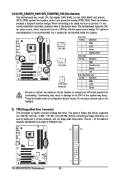
... 1 GND 2 +12V 3 Sense 4 Speed Control SYS_FAN2: Pin No. Definition 1 GND 2 Speed Control 3 Sense 4 +5V SYS_FAN1/PWR_FAN: Pin No. The motherboard supports CPU fan speed control, which requires the use of the connector and the floppy disk drive cable. Definition 1 GND 2 +12V 3 Sense • Be sure...black connector wire is used to prevent your CPU and system from overheating. The types of different color. 34 33 GA-EP43-DS3R/DS3 Motherboard 2 1 - 24 - Do not place a jumper cap on the headers. 6) FDD (Floppy Disk Drive Connector) This connector is the...
... 1 GND 2 +12V 3 Sense 4 Speed Control SYS_FAN2: Pin No. Definition 1 GND 2 Speed Control 3 Sense 4 +5V SYS_FAN1/PWR_FAN: Pin No. The motherboard supports CPU fan speed control, which requires the use of the connector and the floppy disk drive cable. Definition 1 GND 2 +12V 3 Sense • Be sure...black connector wire is used to prevent your CPU and system from overheating. The types of different color. 34 33 GA-EP43-DS3R/DS3 Motherboard 2 1 - 24 - Do not place a jumper cap on the headers. 6) FDD (Floppy Disk Drive Connector) This connector is the...


