
Manual
Page 7
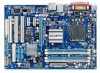
GA-EP41T-USB3 Motherboard Layout LPT KB_MS Coaxial Optical ATX_12V LGA775 PHASE LED CPU_FAN PWR_FAN COMA R_USB30 LAN USB NEC F_AUDIO D720200F1 AUDIO RTL8111D SYS_FAN1 PCIEX16 PCIEX1_1 CODEC PCIEX1_2 SPDIF_O CD_IN PCI1 SPDIF_I PCI2 IT8718 PCI3 FDD DDR3_1 DDR3_2 DDR3_3 DDR3_4 Intel® G41 ATX GA-EP41T-USB3 CLR_CMOS BAT Intel® ICH7 SATA2_0 SATA2_2 SYS_FAN2 SATA2_1 SATA2_3 IDE B_BIOS M_BIOS F_PANEL F_USB1 F_USB2 - 7 -
GA-EP41T-USB3 Motherboard Layout LPT KB_MS Coaxial Optical ATX_12V LGA775 PHASE LED CPU_FAN PWR_FAN COMA R_USB30 LAN USB NEC F_AUDIO D720200F1 AUDIO RTL8111D SYS_FAN1 PCIEX16 PCIEX1_1 CODEC PCIEX1_2 SPDIF_O CD_IN PCI1 SPDIF_I PCI2 IT8718 PCI3 FDD DDR3_1 DDR3_2 DDR3_3 DDR3_4 Intel® G41 ATX GA-EP41T-USB3 CLR_CMOS BAT Intel® ICH7 SATA2_0 SATA2_2 SYS_FAN2 SATA2_1 SATA2_3 IDE B_BIOS M_BIOS F_PANEL F_USB1 F_USB2 - 7 -

Manual
Page 11
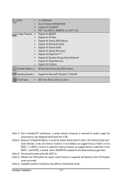
Hardware Installation Internal w Connectors w w w w w w w w w w w w w w Back Panel w Connectors w w w w w w w I/O w Hardware Monitor w w w w w w 1 x 24-pin ATX main power connector 1 x 4-pin ATX 12V power connector 1 x floppy disk drive connector 1 x IDE connector 4 x SATA 3Gb/s connectors 1 x CPU fan header 2 x system fan headers 1 x power fan header 1 x front panel header 1 x front ...
Hardware Installation Internal w Connectors w w w w w w w w w w w w w w Back Panel w Connectors w w w w w w w I/O w Hardware Monitor w w w w w w 1 x 24-pin ATX main power connector 1 x 4-pin ATX 12V power connector 1 x floppy disk drive connector 1 x IDE connector 4 x SATA 3Gb/s connectors 1 x CPU fan header 2 x system fan headers 1 x power fan header 1 x front panel header 1 x front ...
Manual
Page 12
to install two memory modules, we suggest that you install them on the DDR3_1 and DDR3_3 sockets. (Go to GIGABYTE's website for system usage, the actual memory size displayed will be less than 4 GB. (Note 2) Because of chipset limitations, to avoid the ...Advanced Support for Smart Recovery Support for Q-Share Norton Internet Security (OEM version) Operating System w Support for Microsoft® Windows® 7/Vista/XP Form Factor w ATX Form Factor; 30.5cm x 21cm (Note 1) Due to standard PC architecture, a certain amount of memory is reserved for the latest memory support list.) (Note...
to install two memory modules, we suggest that you install them on the DDR3_1 and DDR3_3 sockets. (Go to GIGABYTE's website for system usage, the actual memory size displayed will be less than 4 GB. (Note 2) Because of chipset limitations, to avoid the ...Advanced Support for Smart Recovery Support for Q-Share Norton Internet Security (OEM version) Operating System w Support for Microsoft® Windows® 7/Vista/XP Form Factor w ATX Form Factor; 30.5cm x 21cm (Note 1) Due to standard PC architecture, a certain amount of memory is reserved for the latest memory support list.) (Note...

Manual
Page 21
1-7 Internal Connectors 1 3 17 5 2 10 4 16 13 15 11 8 12 4 1) ATX_12V 2) ATX 3) CPU_FAN 4) SYS_FAN1/2 5) PWR_FAN 6) FDD 7) IDE 8) SATA2_0/1/2/3 9) F_PANEL 6 14 7 9 10) F_AUDIO 11) CD_IN 12) SPDIF_I 13) SPDIF_O 14) F_USB1/F_USB2 15) CLR_CMOS 16) BAT 17) PHASE ...
1-7 Internal Connectors 1 3 17 5 2 10 4 16 13 15 11 8 12 4 1) ATX_12V 2) ATX 3) CPU_FAN 4) SYS_FAN1/2 5) PWR_FAN 6) FDD 7) IDE 8) SATA2_0/1/2/3 9) F_PANEL 6 14 7 9 10) F_AUDIO 11) CD_IN 12) SPDIF_I 13) SPDIF_O 14) F_USB1/F_USB2 15) CLR_CMOS 16) BAT 17) PHASE ...

Manual
Page 22
..., it is used that can lead to an unstable or unbootable system. 3 4 1 2 ATX_12V ATX_12V: Pin No. 1 2 3 4 Definition GND GND +12V +12V 12 24 1 13 ATX ATX: Pin No. 1 2 3 4 5 6 7 8 9 10 11 12 Definition Pin No. 3.3V 13 3.3V 14 GND 15 +5V 16 GND 17 +5V 18 GND 19 Power Good... - 22 - Before connecting the power connector, first make sure the power supply is not connected, the computer will not start. 1/2) ATX_12V/ATX (2x2 12V Power Connector and 2x12 Main Power Connector) With the use of the power connector, the power supply can supply enough stable power ...
..., it is used that can lead to an unstable or unbootable system. 3 4 1 2 ATX_12V ATX_12V: Pin No. 1 2 3 4 Definition GND GND +12V +12V 12 24 1 13 ATX ATX: Pin No. 1 2 3 4 5 6 7 8 9 10 11 12 Definition Pin No. 3.3V 13 3.3V 14 GND 15 +5V 16 GND 17 +5V 18 GND 19 Power Good... - 22 - Before connecting the power connector, first make sure the power supply is not connected, the computer will not start. 1/2) ATX_12V/ATX (2x2 12V Power Connector and 2x12 Main Power Connector) With the use of the power connector, the power supply can supply enough stable power ...

Manual
Page 50
... Suspend) sleep state. Instant-Off Press the power button and then the system will enter suspend mode. Note: To use this function, you need an ATX power supply providing at any time. Press and hold the power button for less than in a low power mode. In S1 sleep state, the system...
... Suspend) sleep state. Instant-Off Press the power button and then the system will enter suspend mode. Note: To use this function, you need an ATX power supply providing at any time. Press and hold the power button for less than in a low power mode. In S1 sleep state, the system...

Manual
Page 51
Select 32-bit mode when you install 64-bit Windows 7/Vista. Password Set a password with up event. Press on this function, you need an ATX power supply providing at least 1A on the +5VSB lead. EuP Support Determines whether to let the system consume less than 1W power in a month. ... of the AC power. Memory The system returns to its last known awake state upon the return of the AC power. Note: you need an ATX power supply providing at least 1A on the +5VSB lead. When prompted for your Windows 7/Vista operating system. Note: When using this item is set...
Select 32-bit mode when you install 64-bit Windows 7/Vista. Password Set a password with up event. Press on this function, you need an ATX power supply providing at least 1A on the +5VSB lead. EuP Support Determines whether to let the system consume less than 1W power in a month. ... of the AC power. Memory The system returns to its last known awake state upon the return of the AC power. Note: you need an ATX power supply providing at least 1A on the +5VSB lead. When prompted for your Windows 7/Vista operating system. Note: When using this item is set...

Manual
Page 81
... procedure below to the motherboard. Yes Isolate the short circuit. Is the power connector of the CPU cooler connected to the CPU securely. Connect the ATX main power cable and the 12V power cable. Make sure the graphics card is verified and solved. No Check if the CPU cooler is installed...
... procedure below to the motherboard. Yes Isolate the short circuit. Is the power connector of the CPU cooler connected to the CPU securely. Connect the ATX main power cable and the 12V power cable. Make sure the graphics card is verified and solved. No Check if the CPU cooler is installed...
