Manual
Page 3
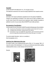
...is 1.0. For detailed product information, carefully read the Quick Installation Guide included with the product. Disclaimer Information in the use GIGABYTE's unique features, read or download the information on/from the Support&Downloads\Motherboard\Technology Guide page on our website. Documentation ... Your Motherboard Revision The revision number on how to their respective owners. For instructions on your motherboard revision before updating motherboard BIOS, drivers, or when looking for technical information. Copyright © 2009 GIGA-BYTE TECHNOLOGY CO., LTD. No part of ...
...is 1.0. For detailed product information, carefully read the Quick Installation Guide included with the product. Disclaimer Information in the use GIGABYTE's unique features, read or download the information on/from the Support&Downloads\Motherboard\Technology Guide page on our website. Documentation ... Your Motherboard Revision The revision number on how to their respective owners. For instructions on your motherboard revision before updating motherboard BIOS, drivers, or when looking for technical information. Copyright © 2009 GIGA-BYTE TECHNOLOGY CO., LTD. No part of ...
Manual
Page 4
Table of Contents Box Contents...6 Optional Items...6 GA-EP41T-UD3L Motherboard Layout 7 Block Diagram...8 Chapter 1 Hardware Installation 9 1-1 Installation Precautions 9 1-2 Product Specifications 10 1-3 Installing the CPU and CPU Cooler ... Installing an Expansion Card 18 1-6 Back Panel Connectors 19 1-7 Internal Connectors 21 Chapter 2 BIOS Setup 31 2-1 Startup Screen 32 2-2 The Main Menu 33 2-3 MB Intelligent Tweaker(M.I.T 35 2-4 Standard CMOS Features 41 2-5 Advanced BIOS Features 43 2-6 Integrated Peripherals 46 2-7 Power Management Setup 49 2-8 PnP/PCI Configurations 51 ...
Table of Contents Box Contents...6 Optional Items...6 GA-EP41T-UD3L Motherboard Layout 7 Block Diagram...8 Chapter 1 Hardware Installation 9 1-1 Installation Precautions 9 1-2 Product Specifications 10 1-3 Installing the CPU and CPU Cooler ... Installing an Expansion Card 18 1-6 Back Panel Connectors 19 1-7 Internal Connectors 21 Chapter 2 BIOS Setup 31 2-1 Startup Screen 32 2-2 The Main Menu 33 2-3 MB Intelligent Tweaker(M.I.T 35 2-4 Standard CMOS Features 41 2-5 Advanced BIOS Features 43 2-6 Integrated Peripherals 46 2-7 Power Management Setup 49 2-8 PnP/PCI Configurations 51 ...

Manual
Page 5
... 58 3-3 Technical Manuals 58 3-4 Contact...59 3-5 System...59 3-6 Download Center 60 Chapter 4 Unique Features 61 4-1 Xpress Recovery2 61 4-2 BIOS Update Utilities 64 4-2-1 Updating the BIOS with the Q-Flash Utility 64 4-2-2 Updating the BIOS with the @BIOS Utility 67 4-3 EasyTune 6...68 4-4 Dynamic Energy Saver Advanced 69 4-5 Q-Share...71 4-6 Time Repair...72 Chapter 5 Appendix...73 5-1 Configuring...
... 58 3-3 Technical Manuals 58 3-4 Contact...59 3-5 System...59 3-6 Download Center 60 Chapter 4 Unique Features 61 4-1 Xpress Recovery2 61 4-2 BIOS Update Utilities 64 4-2-1 Updating the BIOS with the Q-Flash Utility 64 4-2-2 Updating the BIOS with the @BIOS Utility 67 4-3 EasyTune 6...68 4-4 Dynamic Energy Saver Advanced 69 4-5 Q-Share...71 4-6 Time Repair...72 Chapter 5 Appendix...73 5-1 Configuring...

Manual
Page 8
Block Diagram PCIe CLK (100 MHz) 1 PCI Express x16 PCI Express x16 PCI Express Bus 3 PCI Express x1 x1 LAN RJ45 RTL8111D x1 x1 x1 PCIe CLK (100 MHz) PCI Bus LGA775 CPU CPU CLK+/(333/266/200 MHz) Host Interface Intel® G41 DDR3 1333 (O.C.)/1066/800 MHz Dual Channel Memory GMCH CLK (333/266/200 MHz) Intel® ICH7 CODEC Dual BIOS ATA-100/66/33 IDE Channel 4 SATA 3Gb/s 8 USB Ports IT8718 Floppy LPT Port COM Port PS/2 KB/Mouse Surround Speaker Out Center/Subwoofer Speaker Out Side Speaker Out MIC Line Out Line In S/PDIF In S/PDIF Out 3 PCI PCI CLK (33 MHz) - 8 -
Block Diagram PCIe CLK (100 MHz) 1 PCI Express x16 PCI Express x16 PCI Express Bus 3 PCI Express x1 x1 LAN RJ45 RTL8111D x1 x1 x1 PCIe CLK (100 MHz) PCI Bus LGA775 CPU CPU CLK+/(333/266/200 MHz) Host Interface Intel® G41 DDR3 1333 (O.C.)/1066/800 MHz Dual Channel Memory GMCH CLK (333/266/200 MHz) Intel® ICH7 CODEC Dual BIOS ATA-100/66/33 IDE Channel 4 SATA 3Gb/s 8 USB Ports IT8718 Floppy LPT Port COM Port PS/2 KB/Mouse Surround Speaker Out Center/Subwoofer Speaker Out Side Speaker Out MIC Line Out Line In S/PDIF In S/PDIF Out 3 PCI PCI CLK (33 MHz) - 8 -

Manual
Page 12
... Installation - 12 - BIOS w w w w Unique Features w w w w w w w w w w Bundled Software w 2 x 8 Mbit flash Use of licensed AWARD BIOS Support for DualBIOS™ PnP 1.0a, DMI 2.0, SM BIOS 2.4, ACPI 1.0b Support for @BIOS Support for Q-Flash Support for Xpress BIOS Rescue Support for Download ...the system being unable to start or the memory being incorrectly detected, if only one memory module is to GIGABYTE's website for the latest memory support list.) (Note 3) Whether the CPU/system fan speed control function is...
... Installation - 12 - BIOS w w w w Unique Features w w w w w w w w w w Bundled Software w 2 x 8 Mbit flash Use of licensed AWARD BIOS Support for DualBIOS™ PnP 1.0a, DMI 2.0, SM BIOS 2.4, ACPI 1.0b Support for @BIOS Support for Q-Flash Support for Xpress BIOS Rescue Support for Download ...the system being unable to start or the memory being incorrectly detected, if only one memory module is to GIGABYTE's website for the latest memory support list.) (Note 3) Whether the CPU/system fan speed control function is...
Manual
Page 16
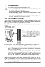
... before installing the memory to prevent hardware damage. • Memory modules have a foolproof design. After the memory is installed, the BIOS will automatically detect the specifications and capacity of the same capacity, brand, speed, and chips be used and installed in Dual Channel mode...SS Four Modules SS SS SS SS (SS=Single-Sided, DS=Double-Sided, "- -"=No Memory) DDR3_1 DDR3_2 DDR3_3 DDR3_4 Due to GIGABYTE's website for optimum performance. 3. If you install them on the DDR3_1 or DDR3_3 socket; Intel Flex Memory Technology offers greater flexibility to...
... before installing the memory to prevent hardware damage. • Memory modules have a foolproof design. After the memory is installed, the BIOS will automatically detect the specifications and capacity of the same capacity, brand, speed, and chips be used and installed in Dual Channel mode...SS Four Modules SS SS SS SS (SS=Single-Sided, DS=Double-Sided, "- -"=No Memory) DDR3_1 DDR3_2 DDR3_3 DDR3_4 Due to GIGABYTE's website for optimum performance. 3. If you install them on the DDR3_1 or DDR3_3 socket; Intel Flex Memory Technology offers greater flexibility to...
Manual
Page 18
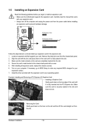
...that came with the expansion card in the expansion slot. 1. Align the card with a screw. 5. Secure the card's metal bracket to make any required BIOS changes for your expansion card in your expansion card. • Always turn off the computer and unplug the power cord from the power outlet before... you begin to correctly install your expansion card(s). 7. If necessary, go to BIOS Setup to the chassis back panel with the slot, and press down on your card. PCI Express x1 Slot PCI Express x16 Slot PCI ...
...that came with the expansion card in the expansion slot. 1. Align the card with a screw. 5. Secure the card's metal bracket to make any required BIOS changes for your expansion card in your expansion card. • Always turn off the computer and unplug the power cord from the power outlet before... you begin to correctly install your expansion card(s). 7. If necessary, go to BIOS Setup to the chassis back panel with the slot, and press down on your card. PCI Express x1 Slot PCI Express x16 Slot PCI ...
Manual
Page 25
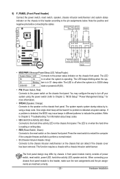
... chassis. The LED is on when the hard drive is detected at system startup. When connecting your system using the power switch (refer to Chapter 2, "BIOS Setup," "Power Management Setup," for information about beep codes. • HD (Hard Drive Activity LED, Blue) Connects to the hard drive activity LED on... the chassis front panel. The LED is off when the system is detected, the BIOS may differ by issuing a beep code. Note the positive and negative pins before connecting the cables. One single short beep will be heard if ...
... chassis. The LED is on when the hard drive is detected at system startup. When connecting your system using the power switch (refer to Chapter 2, "BIOS Setup," "Power Management Setup," for information about beep codes. • HD (Hard Drive Activity LED, Blue) Connects to the hard drive activity LED on... the chassis front panel. The LED is off when the system is detected, the BIOS may differ by issuing a beep code. Note the positive and negative pins before connecting the cables. One single short beep will be heard if ...
Manual
Page 28
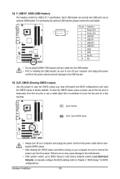
...Failure to do so may cause damage to the motherboard. • After system restart, go to BIOS Setup to load factory defaults (select Load Optimized Defaults) or manually configure the BIOS settings (refer to USB 2.0/1.1 specification. 14) F_USB1/F_USB2 (USB Headers) The headers conform to ...short the two pins or use a metal object like a screwdriver to factory defaults. date information and BIOS configurations) and reset the CMOS values to touch the two pins for BIOS configurations). Hardware Installation - 28 - Each USB header can provide two USB ports via an optional USB...
...Failure to do so may cause damage to the motherboard. • After system restart, go to BIOS Setup to load factory defaults (select Load Optimized Defaults) or manually configure the BIOS settings (refer to USB 2.0/1.1 specification. 14) F_USB1/F_USB2 (USB Headers) The headers conform to ...short the two pins or use a metal object like a screwdriver to factory defaults. date information and BIOS configurations) and reset the CMOS values to touch the two pins for BIOS configurations). Hardware Installation - 28 - Each USB header can provide two USB ports via an optional USB...
Manual
Page 29
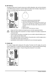
... able to replace the battery by removing the battery: 1. Replace the battery. 4. 16) BAT (Battery) The battery provides power to keep the values (such as BIOS configurations, date, and time information) in accordance with local environmental regulations. 17) PHASE LED The number of lighted LEDs indicates the CPU loading. You may...
... able to replace the battery by removing the battery: 1. Replace the battery. 4. 16) BAT (Battery) The battery provides power to keep the values (such as BIOS configurations, date, and time information) in accordance with local environmental regulations. 17) PHASE LED The number of lighted LEDs indicates the CPU loading. You may...

Manual
Page 31
...recommended that you not alter the default settings (unless you need to) to prevent system instability or other unexpected results. To access the BIOS Setup program, press the key during the POST. Refer to Chapter 5, "Troubleshooting," for how to clear the CMOS values.) - 31... To see more advanced BIOS Setup menu options, you do it is turned on the motherboard. BIOS includes a BIOS Setup program that searches and downloads the latest version of BIOS from the Internet and updates the BIOS. To upgrade the BIOS, use either the GIGABYTE Q-Flash or @BIOS utility. • Q-...
...recommended that you not alter the default settings (unless you need to) to prevent system instability or other unexpected results. To access the BIOS Setup program, press the key during the POST. Refer to Chapter 5, "Troubleshooting," for how to clear the CMOS values.) - 31... To see more advanced BIOS Setup menu options, you do it is turned on the motherboard. BIOS includes a BIOS Setup program that searches and downloads the latest version of BIOS from the Internet and updates the BIOS. To upgrade the BIOS, use either the GIGABYTE Q-Flash or @BIOS utility. • Q-...
Manual
Page 32
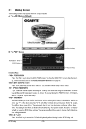
... restart, the device boot order will directly boot from the device configured in Boot Menu is effective for subsequent access to accept. Motherboard Model BIOS Version EP41T-UD3L E4 . . . . : BIOS Setup : XpressRecovery2 : Boot Menu : Qflash 09/21/2009-G41-ICH7-6A79PG05C-00 Function Keys Function Keys Function Keys: : POST SCREEN Press the key to...
... restart, the device boot order will directly boot from the device configured in Boot Menu is effective for subsequent access to accept. Motherboard Model BIOS Version EP41T-UD3L E4 . . . . : BIOS Setup : XpressRecovery2 : Boot Menu : Qflash 09/21/2009-G41-ICH7-6A79PG05C-00 Function Keys Function Keys Function Keys: : POST SCREEN Press the key to...

Manual
Page 33
... options. • When the system is displayed on the right side of the submenu. • If you do not find the settings you enter the BIOS Setup program, the Main Menu (as usual, select the Load Optimized Defaults item to set your system to display a help screen. 2-2 The Main Menu... Once you want in this chapter are for the menu. Press to BIOS Load CMOS from BIOS BIOS Setup Program Function Keys Move the selection bar to select an item Execute command or enter the submenu Main Menu: Exit the...
... options. • When the system is displayed on the right side of the submenu. • If you do not find the settings you enter the BIOS Setup program, the Main Menu (as usual, select the Load Optimized Defaults item to set your system to display a help screen. 2-2 The Main Menu... Once you want in this chapter are for the menu. Press to BIOS Load CMOS from BIOS BIOS Setup Program Function Keys Move the selection bar to select an item Execute command or enter the submenu Main Menu: Exit the...

Manual
Page 34
...61550; MB Intelligent Tweaker(M.I.T.) Use this menu to configure the clock, frequency and voltages of your system becomes unstable and you have loaded the BIOS default settings, you can also carry out this menu to complete. F12: Load CMOS from a profile created before, without the ...USB, integrated audio, and integrated LAN, etc. Power Management Setup Use this menu to configure all changes and the previous settings remain in BIOS Setup. Set User Password Change, set , or disable password. You can also carry out this task.) Exit Without Saving ...
...61550; MB Intelligent Tweaker(M.I.T.) Use this menu to configure the clock, frequency and voltages of your system becomes unstable and you have loaded the BIOS default settings, you can also carry out this menu to complete. F12: Load CMOS from a profile created before, without the ...USB, integrated audio, and integrated LAN, etc. Power Management Setup Use this menu to configure all changes and the previous settings remain in BIOS Setup. Set User Password Change, set , or disable password. You can also carry out this task.) Exit Without Saving ...

Manual
Page 35
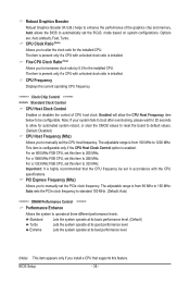
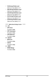
... result in damage to CPU, chipset, or memory and reduce the useful life of these components. This page is dependent on your overall system configurations. BIOS Setup 2-3 MB Intelligent Tweaker(M.I.T.) CMOS Setup Utility-Copyright (C) 1984-2009 Award Software MB Intelligent Tweaker(M.I.T.) Robust Graphics Booster CPU Clock Ratio (Note) Fine CPU Clock...
... result in damage to CPU, chipset, or memory and reduce the useful life of these components. This page is dependent on your overall system configurations. BIOS Setup 2-3 MB Intelligent Tweaker(M.I.T.) CMOS Setup Utility-Copyright (C) 1984-2009 Award Software MB Intelligent Tweaker(M.I.T.) Robust Graphics Booster CPU Clock Ratio (Note) Fine CPU Clock...
Manual
Page 36
...Allows you to alter the clock ratio for the installed CPU. For a 1066 MHz FSB CPU, set this item to 150 MHz. Auto allows the BIOS to enhance the performance of CPU host clock. This item is configurable only if the CPU Host Clock Control option is from 100 MHz to... manually set the PCIe clock frequency. BIOS Setup - 36 - Important: It is installed. Enabled will allow for the installed CPU. Auto sets the PCIe clock frequency to standard 100 MHz. (Default:...
...Allows you to alter the clock ratio for the installed CPU. For a 1066 MHz FSB CPU, set this item to 150 MHz. Auto allows the BIOS to enhance the performance of CPU host clock. This item is configurable only if the CPU Host Clock Control option is from 100 MHz to... manually set the PCIe clock frequency. BIOS Setup - 36 - Important: It is installed. Enabled will allow for the installed CPU. Auto sets the PCIe clock frequency to standard 100 MHz. (Default:...
Manual
Page 37
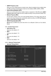
... sets memory multiplier according to fix the chipset frequency at system bootup. tRP Options are dependent on CPU FSB and the (G)MCH Frequency Latch settings. BIOS Setup (G)MCH Frequency Latch Allows you to the fixed frequency. Options are: Auto (default), Manual. >>>>> Standard Timing Control CAS Latency Time Options are : Auto (default...
... sets memory multiplier according to fix the chipset frequency at system bootup. tRP Options are dependent on CPU FSB and the (G)MCH Frequency Latch settings. BIOS Setup (G)MCH Frequency Latch Allows you to the fixed frequency. Options are: Auto (default), Manual. >>>>> Standard Timing Control CAS Latency Time Options are : Auto (default...
Manual
Page 38
... Static tRead Value Options are : Auto (default), 0-Normal, 1-Advanced. tRD Phase2 Adjustment Options are : Auto (default), 1~15. ESC: Exit F1: General Help F7: Optimized Defaults BIOS Setup - 38 - tRD Phase1 Adjustment Options are : Auto (default), 1~31. tWTR Options are : Auto (default), 0-Normal, 1-Advanced. tRD Phase3 Adjustment Options are : Auto (default), 1~255...
... Static tRead Value Options are : Auto (default), 0-Normal, 1-Advanced. tRD Phase2 Adjustment Options are : Auto (default), 1~15. ESC: Exit F1: General Help F7: Optimized Defaults BIOS Setup - 38 - tRD Phase1 Adjustment Options are : Auto (default), 1~31. tWTR Options are : Auto (default), 0-Normal, 1-Advanced. tRD Phase3 Adjustment Options are : Auto (default), 1~255...
Manual
Page 39
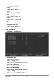
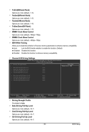
... are : Auto (default), +8~-7. - 39 - Ctrl Driving Pull-Up Level Options are : Auto (default), 1~15. Twr2wr(Different Rank) Options are : Auto (default), 1~15. Auto Lets the BIOS decide whether to enable this function. (Default) Disabled Disables this function to enhance memory compatibility. Channel A/B Driving Settings CMOS Setup Utility-Copyright (C) 1984-2009 Award...(Different Rank) Options are : Auto (default), 1~15. DIMM2 Clock Skew Control Options are: Auto (default), +800ps~-700ps. ESC: Exit F1: General Help F7: Optimized Defaults BIOS Setup
... are : Auto (default), +8~-7. - 39 - Ctrl Driving Pull-Up Level Options are : Auto (default), 1~15. Twr2wr(Different Rank) Options are : Auto (default), 1~15. Auto Lets the BIOS decide whether to enable this function. (Default) Disabled Disables this function to enhance memory compatibility. Channel A/B Driving Settings CMOS Setup Utility-Copyright (C) 1984-2009 Award...(Different Rank) Options are : Auto (default), 1~15. DIMM2 Clock Skew Control Options are: Auto (default), +800ps~-700ps. ESC: Exit F1: General Help F7: Optimized Defaults BIOS Setup
Manual
Page 40
... Options are : Auto (default), +8~-7. ICH I/O The default is Auto. >>> DRAM DRAM Voltage The default is Auto. Ctrl Driving Pull-Down Level Options are : Auto (default), +8~-7. BIOS Setup - 40 - Clk Driving Pull-Up Level Options are : Auto (default), +8~-7.
... Options are : Auto (default), +8~-7. ICH I/O The default is Auto. >>> DRAM DRAM Voltage The default is Auto. Ctrl Driving Pull-Down Level Options are : Auto (default), +8~-7. BIOS Setup - 40 - Clk Driving Pull-Up Level Options are : Auto (default), +8~-7.


