Manual
Page 1
GA-EP41T-UD3L LGA775 socket motherboard for Intel® Core™ processor family/ Intel® Pentium® processor family/Intel® Celeron® processor family User's Manual Rev. 1101 12ME-41TUD3L-1101R
GA-EP41T-UD3L LGA775 socket motherboard for Intel® Core™ processor family/ Intel® Pentium® processor family/Intel® Celeron® processor family User's Manual Rev. 1101 12ME-41TUD3L-1101R
Manual
Page 2
Motherboard GA-EP41T-UD3L Nov. 12, 2009 Motherboard GA-EP41T-UD3L Nov. 12, 2009
Motherboard GA-EP41T-UD3L Nov. 12, 2009 Motherboard GA-EP41T-UD3L Nov. 12, 2009
Manual
Page 3
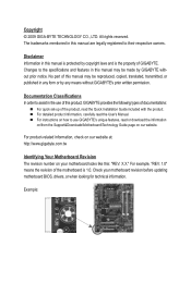
... reproduced, copied, translated, transmitted, or published in this product, GIGABYTE provides the following types of documentations: For quick set-up of the motherboard is 1.0. For instructions on your motherboard revision before updating motherboard BIOS, drivers, or when looking for technical information. For example,... Guide included with the product. For product-related information, check on our website at: http://www.gigabyte.com.tw Identifying Your Motherboard Revision The revision number on how to the specifications and features in any form or by any means...
... reproduced, copied, translated, transmitted, or published in this product, GIGABYTE provides the following types of documentations: For quick set-up of the motherboard is 1.0. For instructions on your motherboard revision before updating motherboard BIOS, drivers, or when looking for technical information. For example,... Guide included with the product. For product-related information, check on our website at: http://www.gigabyte.com.tw Identifying Your Motherboard Revision The revision number on how to the specifications and features in any form or by any means...
Manual
Page 4
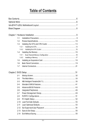
Table of Contents Box Contents...6 Optional Items...6 GA-EP41T-UD3L Motherboard Layout 7 Block Diagram...8 Chapter 1 Hardware Installation 9 1-1 Installation Precautions 9 1-2 Product Specifications 10 1-3 Installing the CPU and CPU Cooler 13 1-3-1 Installing the CPU 13 1-3-2 Installing the CPU ...
Table of Contents Box Contents...6 Optional Items...6 GA-EP41T-UD3L Motherboard Layout 7 Block Diagram...8 Chapter 1 Hardware Installation 9 1-1 Installation Precautions 9 1-2 Product Specifications 10 1-3 Installing the CPU and CPU Cooler 13 1-3-1 Installing the CPU 13 1-3-2 Installing the CPU ...
Manual
Page 6
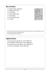
...-1FD001-7*R) 2-port USB 2.0 bracket (Part No. 12CR1-1UB030-5*R) 2-port SATA power cable (Part No. 12CF1-2SERPW-0*R) S/PDIF In cable (Part No. 12CR1-1SPDIN-0*R) - 6 - Box Contents GA-EP41T-UD3L motherboard Motherboard driver disk User's Manual Quick Installation Guide One IDE cable Two SATA 3Gb/s cables I/O Shield • The box contents above are subject to change without...
...-1FD001-7*R) 2-port USB 2.0 bracket (Part No. 12CR1-1UB030-5*R) 2-port SATA power cable (Part No. 12CF1-2SERPW-0*R) S/PDIF In cable (Part No. 12CR1-1SPDIN-0*R) - 6 - Box Contents GA-EP41T-UD3L motherboard Motherboard driver disk User's Manual Quick Installation Guide One IDE cable Two SATA 3Gb/s cables I/O Shield • The box contents above are subject to change without...
Manual
Page 7
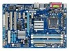
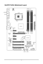
GA-EP41T-UD3L Motherboard Layout LPT KB_MS Coaxial Optical ATX_12V LGA775 PHASE_LED CPU_FAN PWR_FAN COM R_USB LAN USB F_AUDIO AUDIO SYS_FAN1 PCIEX1_1 RTL8111D PCIEX16 PCIEX1_2 CODEC PCIEX1_3 SPDIF_O CD_IN PCI1 SPDIF_I PCI2 IT8718 PCI3 FDD DDR3_1 DDR3_2 DDR3_3 DDR3_4 Intel® G41 ATX GA-EP41T-UD3L CLR_CMOS BAT Intel® ICH7 SATA2_0 SATA2_2 SYS_FAN2 SATA2_1 SATA2_3 IDE B_BIOS M_BIOS F_PANEL F_USB1 F_USB2 - 7 -
GA-EP41T-UD3L Motherboard Layout LPT KB_MS Coaxial Optical ATX_12V LGA775 PHASE_LED CPU_FAN PWR_FAN COM R_USB LAN USB F_AUDIO AUDIO SYS_FAN1 PCIEX1_1 RTL8111D PCIEX16 PCIEX1_2 CODEC PCIEX1_3 SPDIF_O CD_IN PCI1 SPDIF_I PCI2 IT8718 PCI3 FDD DDR3_1 DDR3_2 DDR3_3 DDR3_4 Intel® G41 ATX GA-EP41T-UD3L CLR_CMOS BAT Intel® ICH7 SATA2_0 SATA2_2 SYS_FAN2 SATA2_1 SATA2_3 IDE B_BIOS M_BIOS F_PANEL F_USB1 F_USB2 - 7 -

Manual
Page 9
...'s manual and follow these procedures: • Prior to the use of electrostatic discharge (ESD). Chapter 1 Hardware Installation 1-1 Installation Precautions The motherboard contains numerous delicate electronic circuits and components which can lead to damage to system components as well as physical harm to the user. •... ESD wrist strap, keep your hands dry and first touch a metal object to eliminate static electricity. • Prior to installing the motherboard, please have it on top of an antistatic pad or within the computer casing. • Do not place the computer system on ...
...'s manual and follow these procedures: • Prior to the use of electrostatic discharge (ESD). Chapter 1 Hardware Installation 1-1 Installation Precautions The motherboard contains numerous delicate electronic circuits and components which can lead to damage to system components as well as physical harm to the user. •... ESD wrist strap, keep your hands dry and first touch a metal object to eliminate static electricity. • Prior to installing the motherboard, please have it on top of an antistatic pad or within the computer casing. • Do not place the computer system on ...

Manual
Page 12
... on the DDR3_1 and DDR3_3 sockets. (Go to install two memory modules, we suggest that you install. (Note 4) Available functions in EasyTune may differ by motherboard model. to GIGABYTE's website for system usage, the actual memory size displayed will depend on the DDR3_1 or DDR3_3 socket;
... on the DDR3_1 and DDR3_3 sockets. (Go to install two memory modules, we suggest that you install. (Note 4) Available functions in EasyTune may differ by motherboard model. to GIGABYTE's website for system usage, the actual memory size displayed will depend on the DDR3_1 or DDR3_3 socket;
Manual
Page 13
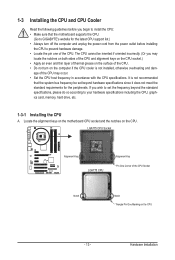
...• Apply an even and thin layer of thermal grease on the computer if the CPU cooler is not recommended that the motherboard supports the CPU. (Go to GIGABYTE's website for the peripherals. Hardware Installation 1-3 Installing the CPU and CPU Cooler Read the following guidelines before installing the CPU to...Alignment Key Pin One Corner of the CPU Socket Notch Notch Triangle Pin One Marking on the CPU. Locate the alignment keys on the motherboard CPU socket and the notches on the CPU - 13 - The CPU cannot be set the frequency beyond hardware specifications since it does not...
...• Apply an even and thin layer of thermal grease on the computer if the CPU cooler is not recommended that the motherboard supports the CPU. (Go to GIGABYTE's website for the peripherals. Hardware Installation 1-3 Installing the CPU and CPU Cooler Read the following guidelines before installing the CPU to...Alignment Key Pin One Corner of the CPU Socket Notch Notch Triangle Pin One Marking on the CPU. Locate the alignment keys on the motherboard CPU socket and the notches on the CPU - 13 - The CPU cannot be set the frequency beyond hardware specifications since it does not...
Manual
Page 14
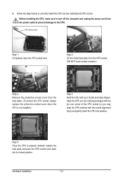
... the load plate and push the CPU socket lever back into position. Before installing the CPU, make sure to correctly install the CPU into the motherboard CPU socket.
... the load plate and push the CPU socket lever back into position. Before installing the CPU, make sure to correctly install the CPU into the motherboard CPU socket.

Manual
Page 15
...shows, the installation is to install.) Step 3: Place the cooler atop the CPU, aligning the four push pins through the pin holes on the motherboard. Direction of the Arrow Sign on the Male Push Pin Male Push Pin The Top of Female Push Pin Female Push Pin Step 2: Before installing... the example cooler.) Step 1: Apply an even and thin layer of thermal grease on the surface of arrow is to remove the cooler, on the motherboard. Inadequately removing the CPU cooler may adhere to the CPU fan header (CPU_FAN) on the contrary, is complete. Step 6: Finally, attach the power ...
...shows, the installation is to install.) Step 3: Place the cooler atop the CPU, aligning the four push pins through the pin holes on the motherboard. Direction of the Arrow Sign on the Male Push Pin Male Push Pin The Top of Female Push Pin Female Push Pin Step 2: Before installing... the example cooler.) Step 1: Apply an even and thin layer of thermal grease on the surface of arrow is to remove the cooler, on the motherboard. Inadequately removing the CPU cooler may adhere to the CPU fan header (CPU_FAN) on the contrary, is complete. Step 6: Finally, attach the power ...
Manual
Page 16
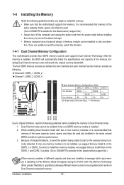
...is operating in Dual Channel mode. 1. to start or the memory being unable to install two memory modules, we suggest that the motherboard supports the memory. After the memory is installed, the BIOS will automatically detect the specifications and capacity of chipset limitations, to avoid... incorrectly detected, if only one direction. Hardware Installation - 16 - Because of the memory. A memory module can be used. (Go to GIGABYTE's website for the latest memory support list.) When memory modules of the same capacity, brand, speed, and chips be enabled if only one ...
...is operating in Dual Channel mode. 1. to start or the memory being unable to install two memory modules, we suggest that the motherboard supports the memory. After the memory is installed, the BIOS will automatically detect the specifications and capacity of chipset limitations, to avoid... incorrectly detected, if only one direction. Hardware Installation - 16 - Because of the memory. A memory module can be used. (Go to GIGABYTE's website for the latest memory support list.) When memory modules of the same capacity, brand, speed, and chips be enabled if only one ...

Manual
Page 17
... is securely inserted. - 17 - Step 2: The clips at both ends of the memory module. As indicated in one direction. Place the memory module on this motherboard. Follow the steps below to correctly install your fingers on the top edge of the memory socket. Hardware Installation Spread the retaining clips at both...
... is securely inserted. - 17 - Step 2: The clips at both ends of the memory module. As indicated in one direction. Place the memory module on this motherboard. Follow the steps below to correctly install your fingers on the top edge of the memory socket. Hardware Installation Spread the retaining clips at both...
Manual
Page 18
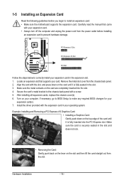
... turn off the computer and unplug the power cord from the power outlet before you begin to install an expansion card: • Make sure the motherboard supports the expansion card. Locate an expansion slot that came with a screw. 5. Make sure the metal contacts on the slot and then lift the card...
... turn off the computer and unplug the power cord from the power outlet before you begin to install an expansion card: • Make sure the motherboard supports the expansion card. Locate an expansion slot that came with a screw. 5. Make sure the metal contacts on the slot and then lift the card...
Manual
Page 19
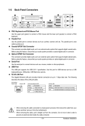
... (purple) to 1 Gbps data rate. Parallel Port Use the parallel port to an external audio system that your device and then remove it from the motherboard. • When removing the cable, pull it side to side to connect devices such as a USB keyboard/mouse, USB printer, USB flash drive and etc...
... (purple) to 1 Gbps data rate. Parallel Port Use the parallel port to an external audio system that your device and then remove it from the motherboard. • When removing the cable, pull it side to side to connect devices such as a USB keyboard/mouse, USB printer, USB flash drive and etc...
Manual
Page 21
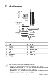
..., make sure your devices are compliant with the connectors you wish to connect. • Before installing the devices, be sure to the connector on the motherboard. - 21 - Hardware Installation
..., make sure your devices are compliant with the connectors you wish to connect. • Before installing the devices, be sure to the connector on the motherboard. - 21 - Hardware Installation

Manual
Page 22
...can lead to an unstable or unbootable system. • The main power connector is turned off and all the components on the motherboard. 1/2) ATX_12V/ATX (2x2 12V Power Connector and 2x12 Main Power Connector) With the use of the power connector, the power supply... power supply cable into pins under the protective cover when using a 2x12 power supply, remove the protective cover from the main power connector on the motherboard. When using a 2x10 power supply. 3 4 1 2 ATX_12V ATX_12V: Pin No. 1 2 3 4 Definition GND GND +12V +12V 12 24 1 13 ATX ATX: Pin No. 1 2 3 4 5 6...
...can lead to an unstable or unbootable system. • The main power connector is turned off and all the components on the motherboard. 1/2) ATX_12V/ATX (2x2 12V Power Connector and 2x12 Main Power Connector) With the use of the power connector, the power supply... power supply cable into pins under the protective cover when using a 2x12 power supply, remove the protective cover from the main power connector on the motherboard. When using a 2x10 power supply. 3 4 1 2 ATX_12V ATX_12V: Pin No. 1 2 3 4 Definition GND GND +12V +12V 12 24 1 13 ATX ATX: Pin No. 1 2 3 4 5 6...

Manual
Page 23
...the correct orientation (the black connector wire is typically designated by a stripe of the connector and the floppy disk drive cable. The motherboard supports CPU fan speed control, which requires the use of floppy disk drives supported are not configuration jumper blocks. Definition 1 GND 2 ... a CPU fan with fan speed control design. The pin 1 of the cable is the ground wire). 3/4/5) CPU_FAN/SYS_FAN1/SYS_FAN2/PWR_FAN (Fan Headers) The motherboard has a 4-pin CPU fan header (CPU_FAN), a 4-pin (SYS_FAN2) and a 3-pin (SYS_FAN1) system fan headers, and a 3-pin power fan header...
...the correct orientation (the black connector wire is typically designated by a stripe of the connector and the floppy disk drive cable. The motherboard supports CPU fan speed control, which requires the use of floppy disk drives supported are not configuration jumper blocks. Definition 1 GND 2 ... a CPU fan with fan speed control design. The pin 1 of the cable is the ground wire). 3/4/5) CPU_FAN/SYS_FAN1/SYS_FAN2/PWR_FAN (Fan Headers) The motherboard has a 4-pin CPU fan header (CPU_FAN), a 4-pin (SYS_FAN2) and a 3-pin (SYS_FAN1) system fan headers, and a 3-pin power fan header...
Manual
Page 26
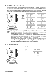
... with your chassis provides an AC'97 front panel audio module, refer to the instructions on each wire instead of the motherboard header. Incorrect connection between the module connector and the motherboard header will be present on both of the front and back panel audio connections simultaneously. You may connect the audio...
... with your chassis provides an AC'97 front panel audio module, refer to the instructions on each wire instead of the motherboard header. Incorrect connection between the module connector and the motherboard header will be present on both of the front and back panel audio connections simultaneously. You may connect the audio...
Manual
Page 27
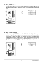
... example, some graphics cards may require you wish to connect an HDMI display to the graphics card and have digital audio output from your motherboard to your motherboard to an audio device that supports digital audio out via an optional S/PDIF In cable. Hardware Installation 12) SPDIF_I (S/PDIF In Header) This header...
... example, some graphics cards may require you wish to connect an HDMI display to the graphics card and have digital audio output from your motherboard to your motherboard to an audio device that supports digital audio out via an optional S/PDIF In cable. Hardware Installation 12) SPDIF_I (S/PDIF In Header) This header...


