Manual
Page 3
... the use GIGABYTE's unique features, read or download the information on/from the Support&Downloads\Motherboard\Technology Guide page on your motherboard revision before updating motherboard BIOS, drivers, or when looking for technical information. For detailed product information, carefully read the Quick Installation Guide included with the product. For example, "REV: 1.0" means the revision of the motherboard is the property of GIGABYTE. Check your motherboard looks like this manual...
... the use GIGABYTE's unique features, read or download the information on/from the Support&Downloads\Motherboard\Technology Guide page on your motherboard revision before updating motherboard BIOS, drivers, or when looking for technical information. For detailed product information, carefully read the Quick Installation Guide included with the product. For example, "REV: 1.0" means the revision of the motherboard is the property of GIGABYTE. Check your motherboard looks like this manual...
Manual
Page 4
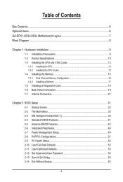
... of Contents Box Contents...6 Optional Items...6 GA-EP41-UD3L/US3L Motherboard Layout 7 Block Diagram...8 Chapter 1 Hardware Installation 9 1-1 Installation Precautions 9 1-2 Product Specifications 10 1-3 Installing the CPU and CPU Cooler 13 1-3-1 Installing the CPU 13 1-3-2 Installing the CPU Cooler 15 1-4 Installing the Memory 16 1-4-1 Dual Channel Memory Configuration 16 1-4-2 Installing a Memory 17 1-5 Installing an Expansion Card 18 1-6 Back Panel Connectors 19 1-7 Internal Connectors 21 Chapter 2 BIOS Setup 31 2-1 Startup Screen 32 2-2 The Main Menu 33 2-3 MB Intelligent...
... of Contents Box Contents...6 Optional Items...6 GA-EP41-UD3L/US3L Motherboard Layout 7 Block Diagram...8 Chapter 1 Hardware Installation 9 1-1 Installation Precautions 9 1-2 Product Specifications 10 1-3 Installing the CPU and CPU Cooler 13 1-3-1 Installing the CPU 13 1-3-2 Installing the CPU Cooler 15 1-4 Installing the Memory 16 1-4-1 Dual Channel Memory Configuration 16 1-4-2 Installing a Memory 17 1-5 Installing an Expansion Card 18 1-6 Back Panel Connectors 19 1-7 Internal Connectors 21 Chapter 2 BIOS Setup 31 2-1 Startup Screen 32 2-2 The Main Menu 33 2-3 MB Intelligent...
Manual
Page 11
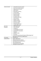
...x 24-pin ATX main power connector 1 x 4-pin ATX 12V power connector 1 x floppy disk drive connector 1 x IDE connector 4 x SATA 3Gb/s connectors 1 x CPU fan header 2 x system fan headers 1 x power fan header 1 x front panel header 1 x front panel audio header 1 x CD In connector 1 x S/PDIF In header 1 x S/PDIF Out header 2 x USB 2.0/1.1 headers 1 x power LED header 1 x chassis intrusion header 1 x clearing CMOS jumper 1 x PS/2 keyboard port 1 x PS/2 mouse port 1 x parallel port 1 x coaxial S/PDIF Out connector 1 x optical S/PDIF Out connector 1 x serial port 4 x USB 2.0/1.1 ports 1 x RJ-45 port...
...x 24-pin ATX main power connector 1 x 4-pin ATX 12V power connector 1 x floppy disk drive connector 1 x IDE connector 4 x SATA 3Gb/s connectors 1 x CPU fan header 2 x system fan headers 1 x power fan header 1 x front panel header 1 x front panel audio header 1 x CD In connector 1 x S/PDIF In header 1 x S/PDIF Out header 2 x USB 2.0/1.1 headers 1 x power LED header 1 x chassis intrusion header 1 x clearing CMOS jumper 1 x PS/2 keyboard port 1 x PS/2 mouse port 1 x parallel port 1 x coaxial S/PDIF Out connector 1 x optical S/PDIF Out connector 1 x serial port 4 x USB 2.0/1.1 ports 1 x RJ-45 port...
Manual
Page 16
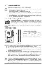
..., speed, and chips be populated and remain in Dual Channel mode/performance. Hardware Installation - 16 - When enabling Dual Channel mode with two or four memory modules, it on the DDR2_1 and DDR2_3 sockets. (Go to GIGABYTE's website for optimum performance. 3. to start or the memory being incorrectly detected, if only one DDR2 memory module is operating in the same colored DDR2 sockets for the latest memory support list.) When memory modules...
..., speed, and chips be populated and remain in Dual Channel mode/performance. Hardware Installation - 16 - When enabling Dual Channel mode with two or four memory modules, it on the DDR2_1 and DDR2_3 sockets. (Go to GIGABYTE's website for optimum performance. 3. to start or the memory being incorrectly detected, if only one DDR2 memory module is operating in the same colored DDR2 sockets for the latest memory support list.) When memory modules...
Manual
Page 18
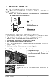
... installing all expansion cards, replace the chassis cover(s). 6. Make sure the card is fully seated in the expansion slot. 1. Turn on the slot and then lift the card straight out from the slot. Install the driver provided with a screw. 5. PCI Express x1 Slot PCI Express x16 Slot PCI Slot Follow the steps below to correctly install your expansion card(s). 7. If necessary, go to BIOS Setup to make any required BIOS changes for your expansion card in the slot. 3. Remove...
... installing all expansion cards, replace the chassis cover(s). 6. Make sure the card is fully seated in the expansion slot. 1. Turn on the slot and then lift the card straight out from the slot. Install the driver provided with a screw. 5. PCI Express x1 Slot PCI Express x16 Slot PCI Slot Follow the steps below to correctly install your expansion card(s). 7. If necessary, go to BIOS Setup to make any required BIOS changes for your expansion card in the slot. 3. Remove...
Manual
Page 30
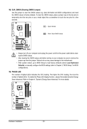
... the power outlet before clearing the CMOS values. • After clearing the CMOS values and before turning on the two pins to temporarily short the two pins or use a metal object like a screwdriver to remove the jumper cap from the jumper. Hardware Installation - 30 - Failure to do so may cause damage to the motherboard. • After system restart, go to BIOS Setup to load factory defaults (select Load Optimized Defaults) or manually configure the BIOS settings...
... the power outlet before clearing the CMOS values. • After clearing the CMOS values and before turning on the two pins to temporarily short the two pins or use a metal object like a screwdriver to remove the jumper cap from the jumper. Hardware Installation - 30 - Failure to do so may cause damage to the motherboard. • After system restart, go to BIOS Setup to load factory defaults (select Load Optimized Defaults) or manually configure the BIOS settings...
Manual
Page 31
... POST when the power is a Windows-based utility that allows the user to modify basic system configuration settings or to quickly and easily upgrade or back up BIOS without entering the operating system. • @BIOS is turned on the motherboard. If this occurs, try to clear the CMOS values and reset the board to default values. (Refer to the "Load Optimized Defaults" section in this chapter or introductions of the battery/ clearing CMOS jumper...
... POST when the power is a Windows-based utility that allows the user to modify basic system configuration settings or to quickly and easily upgrade or back up BIOS without entering the operating system. • @BIOS is turned on the motherboard. If this occurs, try to clear the CMOS values and reset the board to default values. (Refer to the "Load Optimized Defaults" section in this chapter or introductions of the battery/ clearing CMOS jumper...

Manual
Page 32
Motherboard Model BIOS Version EP41-UD3L F2e . . . . : BIOS Setup : XpressRecovery2 : Boot Menu : Qflash 03/11/2009-G41-ICH7-7A69PG0OC-00 Function Keys Function Keys Function Keys: : POST SCREEN Press the key to show the BIOS POST screen at system startup, refer to the instructions on the Full Screen LOGO Show item on page 45. : BIOS SETUP\Q-FLASH Press the key to enter BIOS Setup or to access the Q-Flash utility in BIOS Setup. : XPRESS RECOVERY2 If you to set the first boot device without having to...
Motherboard Model BIOS Version EP41-UD3L F2e . . . . : BIOS Setup : XpressRecovery2 : Boot Menu : Qflash 03/11/2009-G41-ICH7-7A69PG0OC-00 Function Keys Function Keys Function Keys: : POST SCREEN Press the key to show the BIOS POST screen at system startup, refer to the instructions on the Full Screen LOGO Show item on page 45. : BIOS SETUP\Q-FLASH Press the key to enter BIOS Setup or to access the Q-Flash utility in BIOS Setup. : XPRESS RECOVERY2 If you to set the first boot device without having to...
Manual
Page 34
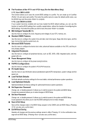
... CPU, memory, etc. Standard CMOS Features Use this menu to configure the system time and date, hard drive types, floppy disk drive types, and the type of errors that stop the system boot, etc. Advanced BIOS Features Use this menu to configure the device boot order, advanced features available on the CPU, and the primary display adapter. Integrated Peripherals Use this menu to configure all peripheral devices, such as IDE, SATA, USB, integrated audio, and integrated LAN, etc. Power Management Setup Use...
... CPU, memory, etc. Standard CMOS Features Use this menu to configure the system time and date, hard drive types, floppy disk drive types, and the type of errors that stop the system boot, etc. Advanced BIOS Features Use this menu to configure the device boot order, advanced features available on the CPU, and the primary display adapter. Integrated Peripherals Use this menu to configure all peripheral devices, such as IDE, SATA, USB, integrated audio, and integrated LAN, etc. Power Management Setup Use...
Manual
Page 35
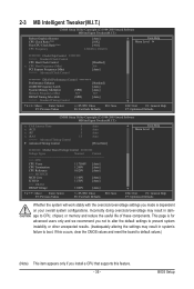
... Host Clock Control x CPU Host Frequency (Mhz) PCI Express Frequency (Mhz) >>>>> Advanced Clock Control [Disabled] 266 [Auto] ******** DRAM Performance Control ******** Performance Enhance [Standard] (G)MCH Frequency Latch [Auto] System Memory Multiplier (SPD) [Auto] Memory Frequency (Mhz) 667 667 DRAM Timing Selectable (SPD) [Auto] >>>>> Standard Timing Control Move Enter: Select F5: Previous Values +/-/PU/PD: Value F10: Save F6: Fail-Safe Defaults ESC: Exit F1: General Help F7: Optimized Defaults CMOS Setup Utility-Copyright (C) 1984-2009 Award Software...
... Host Clock Control x CPU Host Frequency (Mhz) PCI Express Frequency (Mhz) >>>>> Advanced Clock Control [Disabled] 266 [Auto] ******** DRAM Performance Control ******** Performance Enhance [Standard] (G)MCH Frequency Latch [Auto] System Memory Multiplier (SPD) [Auto] Memory Frequency (Mhz) 667 667 DRAM Timing Selectable (SPD) [Auto] >>>>> Standard Timing Control Move Enter: Select F5: Previous Values +/-/PU/PD: Value F10: Save F6: Fail-Safe Defaults ESC: Exit F1: General Help F7: Optimized Defaults CMOS Setup Utility-Copyright (C) 1984-2009 Award Software...

Manual
Page 36
... Clock Control CPU Host Clock Control Enables or disables the control of the graphics chip and memory. The adjustable range is installed. The item is present only if a CPU with the CPU specifications. For a 1066 MHz FSB CPU, set the PCIe clock frequency. For a 1333 MHz FSB CPU, set the CPU host frequency. Robust Graphics Booster Robust Graphics Booster (R.G.B.) helps to enhance the performance of CPU host clock. mode based on system configurations. Note: If your system fails to boot after overclocking...
... Clock Control CPU Host Clock Control Enables or disables the control of the graphics chip and memory. The adjustable range is installed. The item is present only if a CPU with the CPU specifications. For a 1066 MHz FSB CPU, set the PCIe clock frequency. For a 1333 MHz FSB CPU, set the CPU host frequency. Robust Graphics Booster Robust Graphics Booster (R.G.B.) helps to enhance the performance of CPU host clock. mode based on system configurations. Note: If your system fails to boot after overclocking...
Manual
Page 41
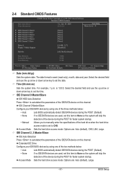
... field and use the up arrow or down arrow key to autodetect the parameters of the IDE/SATA device on this channel. Options are : Auto (default), Large. - 41 - IDE Channel 2, 3 Master/Slave IDE Auto-Detection Press to set the date. Sets the hard drive access mode. Options are : Auto (default), CHS, LBA, Large. The date format is 13:0:0. Time (hh:mm:ss) Sets the system time. BIOS Setup 2-4 Standard CMOS Features CMOS Setup Utility-Copyright (C) 1984-2009 Award Software Standard CMOS Features...
... field and use the up arrow or down arrow key to autodetect the parameters of the IDE/SATA device on this channel. Options are : Auto (default), Large. - 41 - IDE Channel 2, 3 Master/Slave IDE Auto-Detection Press to set the date. Sets the hard drive access mode. Options are : Auto (default), CHS, LBA, Large. The date format is 13:0:0. Time (hh:mm:ss) Sets the system time. BIOS Setup 2-4 Standard CMOS Features CMOS Setup Utility-Copyright (C) 1984-2009 Award Software Standard CMOS Features...
Manual
Page 43
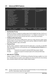
... utility is installed. (Default: Enabled) (Note) This item is present only if you enter BIOS Setup. This feature allows your hard drive. BIOS Setup Press to 3 (Note) No-Execute Memory Protect (Note) CPU Enhanced Halt (C1E) (Note) C2/C2E State Support (Note) CPU Thermal Monitor 2(TM2) (Note) CPU EIST Function (Note) Virtualization Technology (Note) Delay For HDD (Secs) Full Screen LOGO Show Init Display First [Press Enter] [Floppy] [Hard Disk] [CDROM] [Setup] [Enabled] [Enabled] [Disabled] [Enabled] [Enabled] [Disabled] [Enabled] [Enabled] [Enabled] [0] [Enabled...
... utility is installed. (Default: Enabled) (Note) This item is present only if you enter BIOS Setup. This feature allows your hard drive. BIOS Setup Press to 3 (Note) No-Execute Memory Protect (Note) CPU Enhanced Halt (C1E) (Note) C2/C2E State Support (Note) CPU Thermal Monitor 2(TM2) (Note) CPU EIST Function (Note) Virtualization Technology (Note) Delay For HDD (Secs) Full Screen LOGO Show Init Display First [Press Enter] [Floppy] [Hard Disk] [CDROM] [Setup] [Enabled] [Enabled] [Disabled] [Enabled] [Enabled] [Disabled] [Enabled] [Enabled] [Enabled] [0] [Enabled...
Manual
Page 46
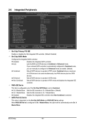
... BIOS set to be automatically set to settings. Disabled Disables the integrated IDE controller when Non-Combined is set SATA devices to operate in SATA mode. Enhanced Sets all SATA devices to Azalia Codec Onboard H/W LAN Green LAN } SMART LAN Onboard LAN Boot ROM Onboard Serial Port 1 Onboard Parallel Port Parallel Port Mode USB 1.0 Controller USB 2.0 Controller USB Keyboard Function USB Mouse Function USB Storage Function [Enabled] [Auto] Ch.0 Master/Slave Ch.2 Master/Slave Ch.3 Master/Slave [Auto] [Enabled] [Disabled] [Press Enter...
... BIOS set to be automatically set to settings. Disabled Disables the integrated IDE controller when Non-Combined is set SATA devices to operate in SATA mode. Enhanced Sets all SATA devices to Azalia Codec Onboard H/W LAN Green LAN } SMART LAN Onboard LAN Boot ROM Onboard Serial Port 1 Onboard Parallel Port Parallel Port Mode USB 1.0 Controller USB 2.0 Controller USB Keyboard Function USB Mouse Function USB Storage Function [Enabled] [Auto] Ch.0 Master/Slave Ch.2 Master/Slave Ch.3 Master/Slave [Auto] [Enabled] [Disabled] [Press Enter...
Manual
Page 47
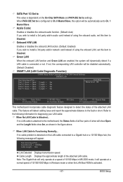
... install a 3rd party add-in network card instead of 10/100/1000 Mbps in the figure above. If no cable problem is detected on the On-Chip SATA Mode and PATA IDE Set to settings. Cable Length Displays the approximate length of the attached LAN cable. When PATA IDE Set to is configured to Ch. 0 Master/Slave, this option will be disabled automatically. (Default: Disabled) SMART LAN (LAN Cable Diagnostic Function) CMOS Setup Utility-Copyright (C) 1984-2009 Award Software SMART LAN Start detecting at a speed...
... install a 3rd party add-in network card instead of 10/100/1000 Mbps in the figure above. If no cable problem is detected on the On-Chip SATA Mode and PATA IDE Set to settings. Cable Length Displays the approximate length of the attached LAN cable. When PATA IDE Set to is configured to Ch. 0 Master/Slave, this option will be disabled automatically. (Default: Disabled) SMART LAN (LAN Cable Diagnostic Function) CMOS Setup Utility-Copyright (C) 1984-2009 Award Software SMART LAN Start detecting at a speed...
Manual
Page 48
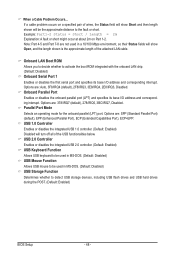
... boot ROM integrated with the onboard LAN chip. (Default: Disabled) Onboard Serial Port 1 Enables or disables the first serial port and specifies its base I /O address and corresponding interrupt. When a Cable Problem Occurs... Note: Part 4-5 and Part 7-8 are : 378/IRQ7 (default), 278/IRQ5, 3BC/IRQ7, Disabled. USB 2.0 Controller Enables or disables the integrated USB 2.0 controller. (Default: Enabled) USB Keyboard Function Allows USB keyboard to detect USB storage devices, including USB flash drives and USB hard drives during the POST. (Default: Enabled) BIOS Setup - 48 - If a cable...
... boot ROM integrated with the onboard LAN chip. (Default: Disabled) Onboard Serial Port 1 Enables or disables the first serial port and specifies its base I /O address and corresponding interrupt. When a Cable Problem Occurs... Note: Part 4-5 and Part 7-8 are : 378/IRQ7 (default), 278/IRQ5, 3BC/IRQ7, Disabled. USB 2.0 Controller Enables or disables the integrated USB 2.0 controller. (Default: Enabled) USB Keyboard Function Allows USB keyboard to detect USB storage devices, including USB flash drives and USB hard drives during the POST. (Default: Enabled) BIOS Setup - 48 - If a cable...
Manual
Page 52
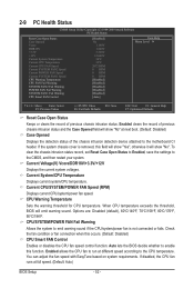
If the system chassis cover is not connected or fails. Current CPU/SYSTEM/POWER FAN Speed (RPM) Displays current CPU/system/power fan speed. Auto lets the BIOS decide whether to enable this occurs. (Default: Disabled) CPU Smart FAN Control Enables or disables the CPU fan speed control function. Options are: Disabled (default), 60oC/140oF, 70oC/158oF, 80oC/176oF, 90oC/194oF. 2-9 PC Health Status CMOS Setup Utility-Copyright (C) 1984-2009 Award Software PC Health Status Reset Case Open Status Case Opened Vcore DDR18V +3.3V +12V Current System ...
If the system chassis cover is not connected or fails. Current CPU/SYSTEM/POWER FAN Speed (RPM) Displays current CPU/system/power fan speed. Auto lets the BIOS decide whether to enable this occurs. (Default: Disabled) CPU Smart FAN Control Enables or disables the CPU fan speed control function. Options are: Disabled (default), 60oC/140oF, 70oC/158oF, 80oC/176oF, 90oC/194oF. 2-9 PC Health Status CMOS Setup Utility-Copyright (C) 1984-2009 Award Software PC Health Status Reset Case Open Status Case Opened Vcore DDR18V +3.3V +12V Current System ...
Manual
Page 57
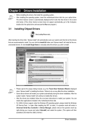
... system restart, "Xpress Install" will continue to install other applications included in the motherboard driver disk. • For USB 2.0 driver support under the Windows XP operating system, please install the Windows XP Service Pack 1 or later. The driver Autorun screen is installing the drivers. After installing the SP1 (or later), if a question mark still exists in Universal Serial Bus Controller in the screen shot below. (If the driver Autorun screen does not appear...
... system restart, "Xpress Install" will continue to install other applications included in the motherboard driver disk. • For USB 2.0 driver support under the Windows XP operating system, please install the Windows XP Service Pack 1 or later. The driver Autorun screen is installing the drivers. After installing the SP1 (or later), if a question mark still exists in Universal Serial Bus Controller in the screen shot below. (If the driver Autorun screen does not appear...
Manual
Page 65
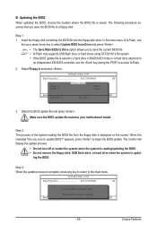
... supports USB flash drive or hard drives using FAT32/16/12 file system. • If the BIOS update file is saved to a hard drive in RAID/AHCI mode or a hard drive attached to an independent IDE/SATA controller, use the up or down arrow key to select Update BIOS from Drive Save BIOS to a floppy disk. Q-Flash Utility v2.09 Flash Type/Size SST 25VF080B 1M Keep0 DfilMe(Is)DfaotuandEnable Floppy A Loa d CMO S Default Enable HDD 1-0 Upda te BIOS from Drive and press . • The Save Main BIOS to Drive option allows you sure to access Q-Flash...
... supports USB flash drive or hard drives using FAT32/16/12 file system. • If the BIOS update file is saved to a hard drive in RAID/AHCI mode or a hard drive attached to an independent IDE/SATA controller, use the up or down arrow key to select Update BIOS from Drive Save BIOS to a floppy disk. Q-Flash Utility v2.09 Flash Type/Size SST 25VF080B 1M Keep0 DfilMe(Is)DfaotuandEnable Floppy A Loa d CMO S Default Enable HDD 1-0 Upda te BIOS from Drive and press . • The Save Main BIOS to Drive option allows you sure to access Q-Flash...
Manual
Page 80
...computer problems. (For reference only.) 1 short: System boots successfully 2 short: CMOS setting error 1 long, 1 short: Memory or motherboard error 1 long, 2 short: Monitor or graphics card error 1 long, 3 short: Keyboard error 1 long, 9 short: BIOS ROM error Continuous long beeps: Graphics card not inserted properly Continuous short beeps: Power error Appendix - 80 - In the Main Menu, press + to load BIOS default settings. 6. Refer to the CMOS, which will clear the CMOS values after the computer shuts down and that's why the light is equipped with power/amplifier. Replace the battery...
...computer problems. (For reference only.) 1 short: System boots successfully 2 short: CMOS setting error 1 long, 1 short: Memory or motherboard error 1 long, 2 short: Monitor or graphics card error 1 long, 3 short: Keyboard error 1 long, 9 short: BIOS ROM error Continuous long beeps: Graphics card not inserted properly Continuous short beeps: Power error Appendix - 80 - In the Main Menu, press + to load BIOS default settings. 6. Refer to the CMOS, which will clear the CMOS values after the computer shuts down and that's why the light is equipped with power/amplifier. Replace the battery...


