Manual
Page 1
GA-EP35-DS3P LGA775 socket motherboard for Intel® CoreTM processor family/ Intel® Pentium® processor family/Intel® Celeron® processor family User's Manual Rev. 2101 12ME-EP35DS3P-2101R
GA-EP35-DS3P LGA775 socket motherboard for Intel® CoreTM processor family/ Intel® Pentium® processor family/Intel® Celeron® processor family User's Manual Rev. 2101 12ME-EP35DS3P-2101R
Manual
Page 2
Motherboard GA-EP35-DS3P Dec. 14, 2007 Motherboard GA-EP35-DS3P Dec. 14, 2007
Motherboard GA-EP35-DS3P Dec. 14, 2007 Motherboard GA-EP35-DS3P Dec. 14, 2007
Manual
Page 3
... manual may be reproduced, copied, translated, transmitted, or published in the use GIGABYTE's unique features, read the User's Manual. „ For instructions on your motherboard revision before updating motherboard BIOS, drivers, or when looking for technical information. Changes to use of GIGABYTE. Copyright © 2007 GIGA-BYTE TECHNOLOGY CO., LTD. For example, "REV: 1.0" means...
... manual may be reproduced, copied, translated, transmitted, or published in the use GIGABYTE's unique features, read the User's Manual. „ For instructions on your motherboard revision before updating motherboard BIOS, drivers, or when looking for technical information. Changes to use of GIGABYTE. Copyright © 2007 GIGA-BYTE TECHNOLOGY CO., LTD. For example, "REV: 1.0" means...
Manual
Page 4
Table of Contents Box Contents ...6 OptionalItems...6 GA-EP35-DS3P Motherboard Layout 7 Block Diagram...8 Chapter 1 Hardware Installation 9 1-1 Installation Precautions 9 1-2 Product Specifications 10 1-3 Installing the CPU and CPU Cooler 13 1-3-1 Installing the CPU 13 1-3-2 Installing the CPU ...
Table of Contents Box Contents ...6 OptionalItems...6 GA-EP35-DS3P Motherboard Layout 7 Block Diagram...8 Chapter 1 Hardware Installation 9 1-1 Installation Precautions 9 1-2 Product Specifications 10 1-3 Installing the CPU and CPU Cooler 13 1-3-1 Installing the CPU 13 1-3-2 Installing the CPU ...
Manual
Page 6
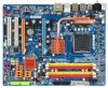
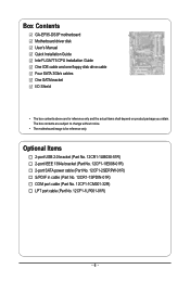
Box Contents GA-EP35-DS3P motherboard Motherboard driver disk User's Manual Quick Installation Guide Intel® LGA775 CPU Installation Guide One IDE cable and one floppy disk drive cable Four SATA 3Gb/s cables One SATA bracket I/O Shield • The box contents above are subject to change without notice. • The motherboard image is for reference only and...
Box Contents GA-EP35-DS3P motherboard Motherboard driver disk User's Manual Quick Installation Guide Intel® LGA775 CPU Installation Guide One IDE cable and one floppy disk drive cable Four SATA 3Gb/s cables One SATA bracket I/O Shield • The box contents above are subject to change without notice. • The motherboard image is for reference only and...
Manual
Page 7
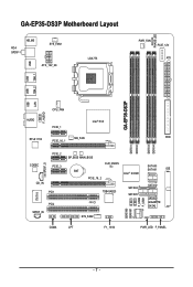
GA-EP35-DS3P Motherboard Layout RCA SPDIF-1 KB_MS SYS_FAN1 USB ATX_12V_2X LGA775 PHASE LED PWR_FAN PCIE_12V ATX 1394_2 1394_1 USB USB GA-EP35-DS3P LAN USB CPU_FAN F_AUDIO AUDIO PCIE_1 Intel® P35 RTL8111B PCIE_16_1 NB_FAN FDD DDRII1 DDRII2 DDRII3 DDRII4 CODEC PCIE_2 PCIE_3 SPDIF_O IT8718 CD_IN PCI1 PCI2 SPDIF_IN BP_BIOS MAIN_BIOS CLR_CMOS BAT PCIE_16_2 Intel® ICH9R TSB43AB23 CI SATAII4 SATAII5 SYS_FAN2 SATAII0 SATAII1 IDE SATAII2 SATAII3 GIGABYTE SATA2 GSATAII0 GSATAII1 F_USB2 F_USB1 COMA LPT F1_1394 PWR_LED F_PANEL - 7 -
GA-EP35-DS3P Motherboard Layout RCA SPDIF-1 KB_MS SYS_FAN1 USB ATX_12V_2X LGA775 PHASE LED PWR_FAN PCIE_12V ATX 1394_2 1394_1 USB USB GA-EP35-DS3P LAN USB CPU_FAN F_AUDIO AUDIO PCIE_1 Intel® P35 RTL8111B PCIE_16_1 NB_FAN FDD DDRII1 DDRII2 DDRII3 DDRII4 CODEC PCIE_2 PCIE_3 SPDIF_O IT8718 CD_IN PCI1 PCI2 SPDIF_IN BP_BIOS MAIN_BIOS CLR_CMOS BAT PCIE_16_2 Intel® ICH9R TSB43AB23 CI SATAII4 SATAII5 SYS_FAN2 SATAII0 SATAII1 IDE SATAII2 SATAII3 GIGABYTE SATA2 GSATAII0 GSATAII1 F_USB2 F_USB1 COMA LPT F1_1394 PWR_LED F_PANEL - 7 -
Manual
Page 9
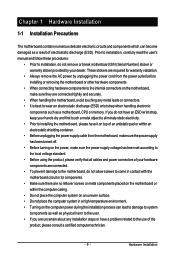
...8226; Before using the product, please verify that all cables and power connectors of your dealer. Chapter 1 Hardware Installation 1-1 Installation Precautions The motherboard contains numerous delicate electronic circuits and components which can lead to damage to system components as well as physical harm to the user. •.... • Do not place the computer system on an uneven surface. • Do not place the computer system in contact with the motherboard circuit or its components. • Make sure there are uncertain about any metal leads or connectors. • It is best to the...
...8226; Before using the product, please verify that all cables and power connectors of your dealer. Chapter 1 Hardware Installation 1-1 Installation Precautions The motherboard contains numerous delicate electronic circuits and components which can lead to damage to system components as well as physical harm to the user. •.... • Do not place the computer system on an uneven surface. • Do not place the computer system in contact with the motherboard circuit or its components. • Make sure there are uncertain about any metal leads or connectors. • It is best to the...
Manual
Page 10
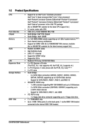
... (Note 1) Š Dual channel memory architecture Š Support for DDR2 1200 (O.C.)/1066/800/667 MHz memory modules (Go to GIGABYTE's website for the latest memory support list.) Š Realtek ALC889A codec Š High Definition Audio Š 2/4/5.1/7.1-channel Š Support...to GIGABYTE's website for the latest CPU support list.) Š L2 cache varies with the PCIE_16_2 slot) (Note 2) Š 2 x PCI slots Š South Bridge: - 6 x SATA 3Gb/s connectors (SATAII0, SATAII1, SATAII2, SATAII3, SATAII4, SATAII5) supporting up to the internal IEEE 1394 header) GA-EP35-DS3P Motherboard ...
... (Note 1) Š Dual channel memory architecture Š Support for DDR2 1200 (O.C.)/1066/800/667 MHz memory modules (Go to GIGABYTE's website for the latest memory support list.) Š Realtek ALC889A codec Š High Definition Audio Š 2/4/5.1/7.1-channel Š Support...to GIGABYTE's website for the latest CPU support list.) Š L2 cache varies with the PCIE_16_2 slot) (Note 2) Š 2 x PCI slots Š South Bridge: - 6 x SATA 3Gb/s connectors (SATAII0, SATAII1, SATAII2, SATAII3, SATAII4, SATAII5) supporting up to the internal IEEE 1394 header) GA-EP35-DS3P Motherboard ...
Manual
Page 12
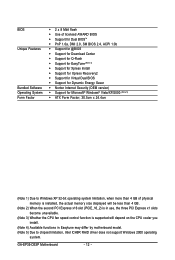
... 3) Whether the CPU fan speed control function is supported will depend on the CPU cooler you install. (Note 4) Available functions in Easytune may differ by motherboard model. (Note 5) Due to chipset limitation, Intel ICH9R RAID driver does not support Windows 2000 operating system. GA-EP35-DS3P Motherboard - 12 -
... 3) Whether the CPU fan speed control function is supported will depend on the CPU cooler you install. (Note 4) Available functions in Easytune may differ by motherboard model. (Note 5) Due to chipset limitation, Intel ICH9R RAID driver does not support Windows 2000 operating system. GA-EP35-DS3P Motherboard - 12 -
Manual
Page 13
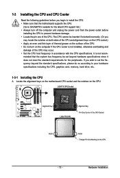
... 775 CPU Alignment Key Pin One Corner of the CPU Socket Notch Notch Triangle Pin One Marking on the CPU. mended that the motherboard supports the CPU. (Go to GIGABYTE's website for the peripherals. If you wish to set beyond the standard specifications, please do so according to your hardware specifications including...
... 775 CPU Alignment Key Pin One Corner of the CPU Socket Notch Notch Triangle Pin One Marking on the CPU. mended that the motherboard supports the CPU. (Go to GIGABYTE's website for the peripherals. If you wish to set beyond the standard specifications, please do so according to your hardware specifications including...
Manual
Page 14
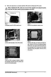
...turn off the computer and unplug the power cord from the power outlet to prevent damage to correctly install the CPU into its locked position. GA-EP35-DS3P Motherboard - 14 - Step 2: Remove the protective socket cover. Step 5: Once the CPU is properly inserted, replace the load plate and push the... CPU socket lever back into the motherboard CPU socket. CPU Socket Lever Step 1: Completely raise the CPU socket lever. Align the CPU pin one marking (triangle) with the pin one...
...turn off the computer and unplug the power cord from the power outlet to prevent damage to correctly install the CPU into its locked position. GA-EP35-DS3P Motherboard - 14 - Step 2: Remove the protective socket cover. Step 5: Once the CPU is properly inserted, replace the load plate and push the... CPU socket lever back into the motherboard CPU socket. CPU Socket Lever Step 1: Completely raise the CPU socket lever. Align the CPU pin one marking (triangle) with the pin one...
Manual
Page 15
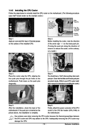
... push pin. (Turning the push pin along the direction of the CPU cooler to your CPU cooler installation manual for instructions on the motherboard. Inadequately removing the CPU cooler may adhere to install.) Step 3: Place the cooler atop the CPU, aligning the four push pins through... the push pins diagonally. If the push pin is to the CPU. Step 4: You should hear a "click" when pushing down on the motherboard. Hardware Installation Step 6: Finally, attach the power connector of arrow is to remove the cooler, on the contrary, is inserted as the example cooler...
... push pin. (Turning the push pin along the direction of the CPU cooler to your CPU cooler installation manual for instructions on the motherboard. Inadequately removing the CPU cooler may adhere to install.) Step 3: Place the cooler atop the CPU, aligning the four push pins through... the push pins diagonally. If the push pin is to the CPU. Step 4: You should hear a "click" when pushing down on the motherboard. Hardware Installation Step 6: Finally, attach the power connector of arrow is to remove the cooler, on the contrary, is inserted as the example cooler...
Manual
Page 16
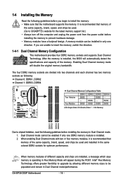
...are installed, a message which says memory is installed, the BIOS will automatically detect the specifications and capacity of the memory. GA-EP35-DS3P Motherboard - 16 - After the memory is operating in Flex Memory Mode will double the original memory bandwidth. Dual Channel mode cannot...DDRII3, DDRII4 Dual Channel Memory Configurations Table DDRII1 DDRII2 DDRII3 Two Modules DS/SS - - The four DDR2 memory sockets are unable to GIGABYTE's website for optimum performance. It is recommended that memory of the same capacity, brand, speed, and chips be used . (Go ...
...are installed, a message which says memory is installed, the BIOS will automatically detect the specifications and capacity of the memory. GA-EP35-DS3P Motherboard - 16 - After the memory is operating in Flex Memory Mode will double the original memory bandwidth. Dual Channel mode cannot...DDRII3, DDRII4 Dual Channel Memory Configurations Table DDRII1 DDRII2 DDRII3 Two Modules DS/SS - - The four DDR2 memory sockets are unable to GIGABYTE's website for optimum performance. It is recommended that memory of the same capacity, brand, speed, and chips be used . (Go ...
Manual
Page 17
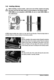
... memory sockets. Follow the steps below to correctly install your fingers on the top edge of the memory socket. Place the memory module on this motherboard. Notch DDR2 DIMM A DDR2 memory module has a notch, so it vertically into place when the memory module is securely inserted. - 17 - Hardware Installation 1-4-2 Installing a Memory...
... memory sockets. Follow the steps below to correctly install your fingers on the top edge of the memory socket. Place the memory module on this motherboard. Notch DDR2 DIMM A DDR2 memory module has a notch, so it vertically into place when the memory module is securely inserted. - 17 - Hardware Installation 1-4-2 Installing a Memory...
Manual
Page 18
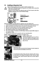
... PCI Express x16 Slot PCI Express x1 Slot PCI Slot Follow the steps below to install an expansion card: • Make sure the motherboard supports the expansion card. After installing all expansion cards, replace the chassis cover(s). 6. Align the card with the expansion card in the slot... x16 slot to release the card and then pull the card straight up from the slot. • The motherboard provides a PCIE_12V power connector, which can supply extra power to prevent hardware damage. Locate an expansion slot that came with a screw. 5. GA-EP35-DS3P Motherboard - 18 -
... PCI Express x16 Slot PCI Express x1 Slot PCI Slot Follow the steps below to install an expansion card: • Make sure the motherboard supports the expansion card. After installing all expansion cards, replace the chassis cover(s). 6. Align the card with the expansion card in the slot... x16 slot to release the card and then pull the card straight up from the slot. • The motherboard provides a PCIE_12V power connector, which can supply extra power to prevent hardware damage. Locate an expansion slot that came with a screw. 5. GA-EP35-DS3P Motherboard - 18 -
Manual
Page 19
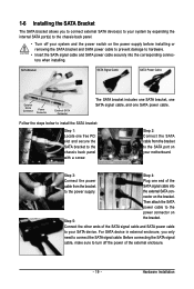
... SATA Connector The SATA bracket includes one SATA bracket, one SATA signal cable, and one free PCI slot and secure the SATA bracket to your motherboard. Connect the other ends of the SATA signal cable and SATA power cable to the chassis back panel with a screw. Follow the steps below to...
... SATA Connector The SATA bracket includes one SATA bracket, one SATA signal cable, and one free PCI slot and secure the SATA bracket to your motherboard. Connect the other ends of the SATA signal cable and SATA power cable to the chassis back panel with a screw. Follow the steps below to...
Manual
Page 20
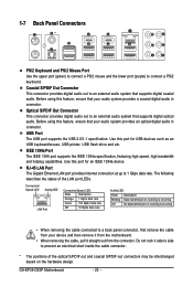
...; When removing the cable, pull it side to side to a back panel connector, first remove the cable from the connector. GA-EP35-DS3P Motherboard - 20 - Coaxial S/PDIF Out Connector This connector provides digital audio out to an external audio system that supports digital coaxial audio. IEEE 1394a Port The ...
...; When removing the cable, pull it side to side to a back panel connector, first remove the cable from the connector. GA-EP35-DS3P Motherboard - 20 - Coaxial S/PDIF Out Connector This connector provides digital audio out to an external audio system that supports digital coaxial audio. IEEE 1394a Port The ...
Manual
Page 22
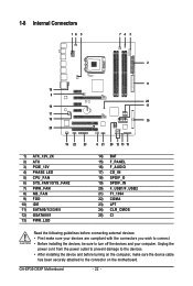
... 18) SPDIF_O 19) SPDIF_IN 20) F_USB1/F_USB2 21) F1_1394 22) COMA 23) LPT 24) CLR_CMOS 25) CI Read the following guidelines before turning on the motherboard. Unplug the power cord from the power outlet to prevent damage to the devices. • After installing the device and before connecting external devices: •... compliant with the connectors you wish to connect. • Before installing the devices, be sure to the connector on the computer, make sure your computer. GA-EP35-DS3P Motherboard - 22 -
... 18) SPDIF_O 19) SPDIF_IN 20) F_USB1/F_USB2 21) F1_1394 22) COMA 23) LPT 24) CLR_CMOS 25) CI Read the following guidelines before turning on the motherboard. Unplug the power cord from the power outlet to prevent damage to the devices. • After installing the device and before connecting external devices: •... compliant with the connectors you wish to connect. • Before installing the devices, be sure to the connector on the computer, make sure your computer. GA-EP35-DS3P Motherboard - 22 -
Manual
Page 23
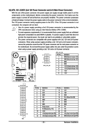
.... • The power connectors are properly installed. The power connector possesses a foolproof design. If a power supply is turned off and all the components on the motherboard. Definition 1 GND(Only for 2x4 pin 12V) 2 GND (Only for 2x4 pin 12V) 3 GND 4 GND 5 +12V (Only for 2x4 pin 12V) 6 +12V (Only for 2x12... a power supply providing a 2x4 12V and a 2x12 power connector, remove the protective covers from the 12V power connector and the main power connector on the motherboard.
.... • The power connectors are properly installed. The power connector possesses a foolproof design. If a power supply is turned off and all the components on the motherboard. Definition 1 GND(Only for 2x4 pin 12V) 2 GND (Only for 2x4 pin 12V) 3 GND 4 GND 5 +12V (Only for 2x4 pin 12V) 6 +12V (Only for 2x12... a power supply providing a 2x4 12V and a 2x12 power connector, remove the protective covers from the 12V power connector and the main power connector on the motherboard.
Manual
Page 24
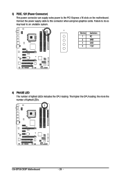
Definition 1 NC 2 GND 3 GND 4 +12V 4) PHASE LED The number of lighted LEDs. 3) PCIE_12V (Power Connector) This power connector can supply extra power to an unstable system. 1 PIin No. Failure to do so may lead to the PCI Express x16 slots on the motherboard. Connect the power supply cable to this connector when using two graphics cards. GA-EP35-DS3P Motherboard - 24 - The higher the CPU loading, the more the number of lighted LEDs indicates the CPU loading.
Definition 1 NC 2 GND 3 GND 4 +12V 4) PHASE LED The number of lighted LEDs. 3) PCIE_12V (Power Connector) This power connector can supply extra power to an unstable system. 1 PIin No. Failure to do so may lead to the PCI Express x16 slots on the motherboard. Connect the power supply cable to this connector when using two graphics cards. GA-EP35-DS3P Motherboard - 24 - The higher the CPU loading, the more the number of lighted LEDs indicates the CPU loading.


