
Manual
Page 5
... Q-Flash Utility 62 4-2-2 Updating the BIOS with the @BIOS Utility 65 4-3 EasyTune 6 ...66 4-4 Dynamic Energy Saver Advanced 67 Chapter 5 Appendix ...69 5-1 Configuring Audio Input and Output 69 5-1-1 Configuring 2/4/5.1/7.1-Channel Audio 69 5-1-2 Installing the S/PDIF In Cable (Optional 71 5-1-3 Configuring Microphone Recording 73 5-1-4 Using the Sound Recorder 75 5-2 Troubleshooting 76 5-2-1 Frequently Asked Questions...
... Q-Flash Utility 62 4-2-2 Updating the BIOS with the @BIOS Utility 65 4-3 EasyTune 6 ...66 4-4 Dynamic Energy Saver Advanced 67 Chapter 5 Appendix ...69 5-1 Configuring Audio Input and Output 69 5-1-1 Configuring 2/4/5.1/7.1-Channel Audio 69 5-1-2 Installing the S/PDIF In Cable (Optional 71 5-1-3 Configuring Microphone Recording 73 5-1-4 Using the Sound Recorder 75 5-2 Troubleshooting 76 5-2-1 Frequently Asked Questions...
Manual
Page 7
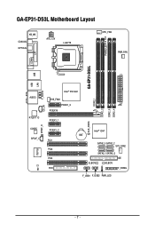
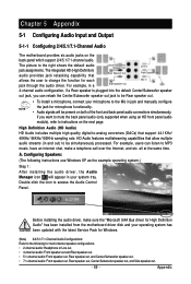
GA-EP31-DS3L Motherboard Layout KB_MS COAXIAL OPTICAL ATX_12V LGA775 CPU_FAN PWR_FAN PHASE LED COMA LPT GA-EP31-DS3L USB USB LAN AUDIO RTL8111C CODEC SPDIF_I CI IT8718 SPDIF_O CD_IN F_AUDIO Intel® P31/G31 DDR2_1 SYS_FAN1 PCIEX1_3 ATX PCIEX16 DDR2_2 DDR2_3 DDR2_4 PCIEX1_1 CLR_CMOS PCIEX1_2 PCI1 PCI2 PCI3 FDD Intel® ICH7 BAT SATA2_0 SATA2_2 SYS_FAN2 SATA2_1 SATA2_3 IDE B_BIOS M_BIOS F_PANEL F_USB1 F_USB2 PWR_LED - 7 -
GA-EP31-DS3L Motherboard Layout KB_MS COAXIAL OPTICAL ATX_12V LGA775 CPU_FAN PWR_FAN PHASE LED COMA LPT GA-EP31-DS3L USB USB LAN AUDIO RTL8111C CODEC SPDIF_I CI IT8718 SPDIF_O CD_IN F_AUDIO Intel® P31/G31 DDR2_1 SYS_FAN1 PCIEX1_3 ATX PCIEX16 DDR2_2 DDR2_3 DDR2_4 PCIEX1_1 CLR_CMOS PCIEX1_2 PCI1 PCI2 PCI3 FDD Intel® ICH7 BAT SATA2_0 SATA2_2 SYS_FAN2 SATA2_1 SATA2_3 IDE B_BIOS M_BIOS F_PANEL F_USB1 F_USB2 PWR_LED - 7 -

Manual
Page 10
...Extreme Edition/Intel® Pentium® 4 processor/ Intel® Celeron® processor in the LGA 775 package (Go to GIGABYTE's website for the latest CPU support list.) Š L2 cache varies with CPU Š 1333/1066/800 MHz FSB ... Š Support for DDR2 1066/800/667 MHz memory modules (Go to GIGABYTE's website for the latest memory support list.) Š Realtek ALC888 codec Š High Definition Audio Š 2/4/5.1/7.1-channel Š Support for S/PDIF In/Out Š Support...the back panel, 4 via the USB brackets connected to the internal USB headers) GA-EP31-DS3L Motherboard - 10 -
...Extreme Edition/Intel® Pentium® 4 processor/ Intel® Celeron® processor in the LGA 775 package (Go to GIGABYTE's website for the latest CPU support list.) Š L2 cache varies with CPU Š 1333/1066/800 MHz FSB ... Š Support for DDR2 1066/800/667 MHz memory modules (Go to GIGABYTE's website for the latest memory support list.) Š Realtek ALC888 codec Š High Definition Audio Š 2/4/5.1/7.1-channel Š Support for S/PDIF In/Out Š Support...the back panel, 4 via the USB brackets connected to the internal USB headers) GA-EP31-DS3L Motherboard - 10 -

Manual
Page 11
... connectors Š 1 x CPU fan header Š 2 x system fan headers Š 1 x power fan header Š 1 x front panel header Š 1 x front panel audio header Š 1 x CD In connector Š 1 x S/PDIF In header Š 1 x S/PDIF Out header Š 2 x USB 2.0/1.1 headers Š 1 x chassis ...Out connector Š 1 x optical S/PDIF Out connector Š 4 x USB 2.0/1.1 ports Š 1 x RJ-45 port Š 6 x audio jacks (Center/Subwoofer Speaker Out/Rear Speaker Out/ Side Speaker Out/Line In/Line Out/Microphone) I/O Controller Š iTE IT8718 chip Hardware Monitor Š ...
... connectors Š 1 x CPU fan header Š 2 x system fan headers Š 1 x power fan header Š 1 x front panel header Š 1 x front panel audio header Š 1 x CD In connector Š 1 x S/PDIF In header Š 1 x S/PDIF Out header Š 2 x USB 2.0/1.1 headers Š 1 x chassis ...Out connector Š 1 x optical S/PDIF Out connector Š 4 x USB 2.0/1.1 ports Š 1 x RJ-45 port Š 6 x audio jacks (Center/Subwoofer Speaker Out/Rear Speaker Out/ Side Speaker Out/Line In/Line Out/Microphone) I/O Controller Š iTE IT8718 chip Hardware Monitor Š ...

Manual
Page 19
...other peripherals. RJ-45 LAN Port The Gigabit Ethernet LAN port provides Internet connection at up to an external audio system that your audio system provides an optical digital audio in connector. The parallel port is occurring • When removing the cable connected to connect devices such as...device and then remove it from the motherboard. • When removing the cable, pull it side to side to an external audio system that supports digital coaxial audio. Parallel Port Use the parallel port to connect a PS/2 keyboard. 1-6 Back Panel Connectors PS/2 Keyboard and PS/2 Mouse ...
...other peripherals. RJ-45 LAN Port The Gigabit Ethernet LAN port provides Internet connection at up to an external audio system that your audio system provides an optical digital audio in connector. The parallel port is occurring • When removing the cable connected to connect devices such as...device and then remove it from the motherboard. • When removing the cable, pull it side to side to an external audio system that supports digital coaxial audio. Parallel Port Use the parallel port to connect a PS/2 keyboard. 1-6 Back Panel Connectors PS/2 Keyboard and PS/2 Mouse ...

Manual
Page 20
... devices such as an optical drive, walkman, etc. This jack can be connected to the default Mic in a 5.1/7.1-channel audio configuration. GA-EP31-DS3L Motherboard - 20 - Center/Subwoofer Speaker Out Jack (Orange) Use this audio jack to connect center/subwoofer speakers in jack ( ). Only microphones still MUST be reconfigured to connect side speakers in Chapter...
... devices such as an optical drive, walkman, etc. This jack can be connected to the default Mic in a 5.1/7.1-channel audio configuration. GA-EP31-DS3L Motherboard - 20 - Center/Subwoofer Speaker Out Jack (Orange) Use this audio jack to connect center/subwoofer speakers in jack ( ). Only microphones still MUST be reconfigured to connect side speakers in Chapter...
Manual
Page 25
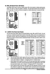
... match the pin assignments of the motherboard header. If your chassis front panel audio module to Chapter 5, "Configuring 2/4/5.1/7.1-Channel Audio." • Some chassis provide a front panel audio module that has different wire assignments, please contact the chassis manufacturer. - 25...) This header can be present on both of the front and back panel audio connections simultaneously. The LED keeps blinking when the system is in Chapter 5, "Configuring 2/4/5.1/7.1-Channel Audio." • Audio signals will make the device unable to indicate system power status. Definition 1 ...
... match the pin assignments of the motherboard header. If your chassis front panel audio module to Chapter 5, "Configuring 2/4/5.1/7.1-Channel Audio." • Some chassis provide a front panel audio module that has different wire assignments, please contact the chassis manufacturer. - 25...) This header can be present on both of the front and back panel audio connections simultaneously. The LED keeps blinking when the system is in Chapter 5, "Configuring 2/4/5.1/7.1-Channel Audio." • Audio signals will make the device unable to indicate system power status. Definition 1 ...

Manual
Page 27
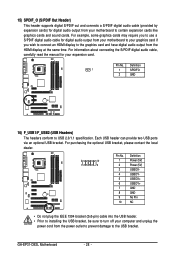
Definition 1 1 CD-L 2 GND 3 GND 4 CD-R 14) SPDIF_I (S/PDIF In Header, Red) This header supports digital S/PDIF in and can connect to the header. Hardware Installation Pin No. Definition 1 Power 2 SPDIFI 3 GND - 27 - 13) CD_IN (CD In Connector, Black) You may connect the audio cable that came with your optical drive to an audio device that supports digital audio out via an optional S/PDIF in cable, please contact the local dealer. 1 Pin No. For purchasing the optional S/PDIF in cable.
Definition 1 1 CD-L 2 GND 3 GND 4 CD-R 14) SPDIF_I (S/PDIF In Header, Red) This header supports digital S/PDIF in and can connect to the header. Hardware Installation Pin No. Definition 1 Power 2 SPDIFI 3 GND - 27 - 13) CD_IN (CD In Connector, Black) You may connect the audio cable that came with your optical drive to an audio device that supports digital audio out via an optional S/PDIF in cable, please contact the local dealer. 1 Pin No. For purchasing the optional S/PDIF in cable.
Manual
Page 28
GA-EP31-DS3L Motherboard - 28 - Each USB header can provide two USB ports via an ...prevent damage to certain expansion cards like graphics cards and sound cards. For information about connecting the S/PDIF digital audio cable, carefully read the manual for your graphics card if you wish to connect an HDMI display to USB ...15) SPDIF_O (S/PDIF Out Header) This header supports digital S/PDIF out and connects a S/PDIF digital audio cable (provided by expansion cards) for digital audio output from your motherboard to the USB bracket. For example, some graphics cards may require you to...
GA-EP31-DS3L Motherboard - 28 - Each USB header can provide two USB ports via an ...prevent damage to certain expansion cards like graphics cards and sound cards. For information about connecting the S/PDIF digital audio cable, carefully read the manual for your graphics card if you wish to connect an HDMI display to USB ...15) SPDIF_O (S/PDIF Out Header) This header supports digital S/PDIF out and connects a S/PDIF digital audio cable (provided by expansion cards) for digital audio output from your motherboard to the USB bracket. For example, some graphics cards may require you to...
Manual
Page 34
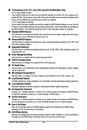
... primary display adapter. „ Integrated Peripherals Use this menu to configure all peripheral devices, such as IDE, SATA, USB, integrated audio, and integrated LAN, etc. „ Power Management Setup Use this task.) GA-EP31-DS3L Motherboard - 34 - It allows you to restrict access to the system and BIOS Setup. „ The Functions of the...
... primary display adapter. „ Integrated Peripherals Use this menu to configure all peripheral devices, such as IDE, SATA, USB, integrated audio, and integrated LAN, etc. „ Power Management Setup Use this task.) GA-EP31-DS3L Motherboard - 34 - It allows you to restrict access to the system and BIOS Setup. „ The Functions of the...
Manual
Page 40
... will turn off all four pairs of wires will detect cabling issue and report the approximate distance to detect the status of using the onboard audio, set this item to Disabled. Part1-2 Status = Open Part3-6 Status = Open Part4-5 Status = Open Part7-8 Status = Open / Length = 0m / Length = 0m /...SMART LAN (LAN Cable Diagnostic Function) CMOS Setup Utility-Copyright (C) 1984-2008 Award Software SMART LAN Start detecting at Port..... Refer to settings. GA-EP31-DS3L Motherboard - 40 - SATA Port 1/3 Set to This value is dependent on the On-Chip SATA Mode and PATA IDE Set to the ...
... will turn off all four pairs of wires will detect cabling issue and report the approximate distance to detect the status of using the onboard audio, set this item to Disabled. Part1-2 Status = Open Part3-6 Status = Open Part4-5 Status = Open Part7-8 Status = Open / Length = 0m / Length = 0m /...SMART LAN (LAN Cable Diagnostic Function) CMOS Setup Utility-Copyright (C) 1984-2008 Award Software SMART LAN Start detecting at Port..... Refer to settings. GA-EP31-DS3L Motherboard - 40 - SATA Port 1/3 Set to This value is dependent on the On-Chip SATA Mode and PATA IDE Set to the ...
Manual
Page 69
...install a microphone, connect your system tray. The integrated HD (High Definition) audio provides jack retasking capability that allow multiple audio streams (in a Side Speaker Out 4-channel audio configuration, if a Rear speaker is plugged into the default Center/Subwoofer speaker ...example operating system.) Step 1: After installing the audio driver, the Audio Manager icon will be simultaneously processed. Chapter 5 Appendix 5-1 Configuring Audio Input and Output 5-1-1 Configuring 2/4/5.1/7.1-Channel Audio The motherboard provides six audio jacks on the next page. If you can...
...install a microphone, connect your system tray. The integrated HD (High Definition) audio provides jack retasking capability that allow multiple audio streams (in a Side Speaker Out 4-channel audio configuration, if a Rear speaker is plugged into the default Center/Subwoofer speaker ...example operating system.) Step 1: After installing the audio driver, the Audio Manager icon will be simultaneously processed. Chapter 5 Appendix 5-1 Configuring Audio Input and Output 5-1-1 Configuring 2/4/5.1/7.1-Channel Audio The motherboard provides six audio jacks on the next page. If you can...

Manual
Page 70
...Mute rear panel output when front headphone plugged in check box. Select the device according to the type of device you connect an audio device to activate the AC'97 functionality, click the tool icon on the left, select 2CH Speaker, 4CH Speaker, 6CH Speaker, ...select the Disable front panel jack detection check box. Configuring Sound Effect: You may configure an audio environment on the Audio I/O tab. D. Muting the Back Panel Audio (For HD Audio Only): Click the tool icon on the Sound Effect tab. B. In the speaker list on the Audio I /O tab. GA-EP31-DS3L Motherboard - 70 -
...Mute rear panel output when front headphone plugged in check box. Select the device according to the type of device you connect an audio device to activate the AC'97 functionality, click the tool icon on the left, select 2CH Speaker, 4CH Speaker, 6CH Speaker, ...select the Disable front panel jack detection check box. Configuring Sound Effect: You may configure an audio environment on the Audio I/O tab. D. Muting the Back Panel Audio (For HD Audio Only): Click the tool icon on the Sound Effect tab. B. In the speaker list on the Audio I /O tab. GA-EP31-DS3L Motherboard - 70 -

Manual
Page 71
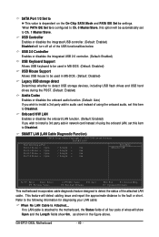
Appendix Optical S/PDIF In Coaxial S/PDIF In S/PDIF In: The S/PDIF in functionality. Installing the S/PDIF In Cable: Step 1: First, attach the connector at the end of the cable to the computer for audio processing. Step 2: Secure the metal bracket to the chassis back panel with a screw. - 71 - A. 5-1-2 Installing the S/PDIF In Cable (Optional) The S/PDIF in cable provides S/PDIF in jacks allow you to input digital audio signals to the SPDIF_I header on your motherboard.
Appendix Optical S/PDIF In Coaxial S/PDIF In S/PDIF In: The S/PDIF in functionality. Installing the S/PDIF In Cable: Step 1: First, attach the connector at the end of the cable to the computer for audio processing. Step 2: Secure the metal bracket to the chassis back panel with a screw. - 71 - A. 5-1-2 Installing the S/PDIF In Cable (Optional) The S/PDIF in cable provides S/PDIF in jacks allow you to input digital audio signals to the SPDIF_I header on your motherboard.

Manual
Page 72
...decoding to get the best audio quality. S/PDIF Coaxial Cable S/PDIF Optical Cable C. In the S/PDIF In/Out Settings dialog box, select an output sampling rate and select (or disable) the output source. B. Configuring S/PDIF out: Click the tool icon in the DIGITAL section. GA-EP31-DS3L Motherboard - 72 - S/PDIF... Out: The S/PDIF out jacks can transmit audio signals to an external decoder for transmitting the S/PDIF digital...
...decoding to get the best audio quality. S/PDIF Coaxial Cable S/PDIF Optical Cable C. In the S/PDIF In/Out Settings dialog box, select an output sampling rate and select (or disable) the output source. B. Configuring S/PDIF out: Click the tool icon in the DIGITAL section. GA-EP31-DS3L Motherboard - 72 - S/PDIF... Out: The S/PDIF out jacks can transmit audio signals to an external decoder for transmitting the S/PDIF digital...

Manual
Page 73
... panel. Step 3: Locate the Volume icon in your system tray. Then configure the jack for microphone functionality. 5-1-3 Configuring Microphone Recording Step 1: After installing the audio driver, the Audio Manager icon will appear in your system tray and click it to open the volume control panel. - 73 - Appendix Double-click the icon to...
... panel. Step 3: Locate the Volume icon in your system tray. Then configure the jack for microphone functionality. 5-1-3 Configuring Microphone Recording Step 1: After installing the audio driver, the Audio Manager icon will appear in your system tray and click it to open the volume control panel. - 73 - Appendix Double-click the icon to...

Manual
Page 74
... sound for your recording device(s) altogether. Select the volume control options you need in the Mixer device list Recording Control GA-EP31-DS3L Motherboard - 74 - Select Realtek HD Audio Input in Master Volume, go to set the volume at a middle level. Step 5: Next, while in Master Volume...recording you set the recording sound level properly. In the Mixer device list, select Realtek HD Audio Input. It is recommended that you just made. (Note) Based on the audio specifications, to adjust the recording sound, use the Recording option to Options and click Properties....
... sound for your recording device(s) altogether. Select the volume control options you need in the Mixer device list Recording Control GA-EP31-DS3L Motherboard - 74 - Select Realtek HD Audio Input in Master Volume, go to set the volume at a middle level. Step 5: Next, while in Master Volume...recording you set the recording sound level properly. In the Mixer device list, select Realtek HD Audio Input. It is recommended that you just made. (Note) Based on the audio specifications, to adjust the recording sound, use the Recording option to Options and click Properties....

Manual
Page 75
... begin the sound recording. 5-1-4 Using the Sound Recorder Recording the Sound: 1. In the Open dialog box, select the sound (.wav) file you have connected the audio input device (e.g. Appendix Front Green In, Front Pink In). Click the Advanced button under a volume control option (e.g. Step 7: After completion, click Start, point to All...
... begin the sound recording. 5-1-4 Using the Sound Recorder Recording the Sound: 1. In the Open dialog box, select the sound (.wav) file you have connected the audio input device (e.g. Appendix Front Green In, Front Pink In). Click the Advanced button under a volume control option (e.g. Step 7: After completion, click Start, point to All...


