Manual
Page 3
.../from the Support&Downloads\Motherboard\Technology Guide page on your motherboard revision before updating motherboard BIOS, drivers, or when looking for technical information. The trademarks mentioned in the use GIGABYTE's unique features, read the User's Manual. For instructions on how to ...their respective owners. For product-related information, check on our website at: http://www.gigabyte.com Identifying Your Motherboard Revision The revision number on our website. Example: Disclaimer Information in any form or by any means without...
.../from the Support&Downloads\Motherboard\Technology Guide page on your motherboard revision before updating motherboard BIOS, drivers, or when looking for technical information. The trademarks mentioned in the use GIGABYTE's unique features, read the User's Manual. For instructions on how to ...their respective owners. For product-related information, check on our website at: http://www.gigabyte.com Identifying Your Motherboard Revision The revision number on our website. Example: Disclaimer Information in any form or by any means without...

Manual
Page 4
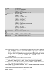
Table of Contents Box Contents...6 Optional Items...6 GA-EG41MFT-US2H Motherboard Layout 7 GA-EG41MFT-US2H Motherboard Block Diagram 8 Chapter 1 Hardware Installation 9 1-1 Installation Precautions 9 1-2 Product Specifications 10 1-3 Installing the CPU and...an Expansion Card 18 1-6 Back Panel Connectors 19 1-7 Internal Connectors 21 Chapter 2 BIOS Setup 31 2-1 Startup Screen 32 2-2 The Main Menu 33 2-3 MB Intelligent Tweaker(M.I.T 35 2-4 Standard CMOS Features 42 2-5 Advanced BIOS Features 44 2-6 Advanced Chipset Features 46 2-7 Integrated Peripherals 48 2-8 Power Management ...
Table of Contents Box Contents...6 Optional Items...6 GA-EG41MFT-US2H Motherboard Layout 7 GA-EG41MFT-US2H Motherboard Block Diagram 8 Chapter 1 Hardware Installation 9 1-1 Installation Precautions 9 1-2 Product Specifications 10 1-3 Installing the CPU and...an Expansion Card 18 1-6 Back Panel Connectors 19 1-7 Internal Connectors 21 Chapter 2 BIOS Setup 31 2-1 Startup Screen 32 2-2 The Main Menu 33 2-3 MB Intelligent Tweaker(M.I.T 35 2-4 Standard CMOS Features 42 2-5 Advanced BIOS Features 44 2-6 Advanced Chipset Features 46 2-7 Integrated Peripherals 48 2-8 Power Management ...
Manual
Page 5
... 60 3-4 Contact...61 3-5 System...61 3-6 Download Center 62 3-7 New Utilities...62 Chapter 4 Unique Features 63 4-1 Xpress Recovery2 63 4-2 BIOS Update Utilities 66 4-2-1 Updating the BIOS with the Q-Flash Utility 66 4-2-2 Updating the BIOS with the @BIOS Utility 69 4-3 EasyTune 6...70 4-4 Dynamic Energy Saver Advanced 71 4-5 Q-Share...73 4-6 SMART Recovery 74 4-7 Auto Green...75 Chapter...
... 60 3-4 Contact...61 3-5 System...61 3-6 Download Center 62 3-7 New Utilities...62 Chapter 4 Unique Features 63 4-1 Xpress Recovery2 63 4-2 BIOS Update Utilities 66 4-2-1 Updating the BIOS with the Q-Flash Utility 66 4-2-2 Updating the BIOS with the @BIOS Utility 69 4-3 EasyTune 6...70 4-4 Dynamic Energy Saver Advanced 71 4-5 Q-Share...73 4-6 SMART Recovery 74 4-7 Auto Green...75 Chapter...
Manual
Page 8
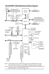
... unavailable. (Note 2) You can use only one of the onboard digital graphics ports (HDMI and DVI-D) for output when in the BIOS Setup program or when during the POST screens. - 8 - GA-EG41MFT-US2H Motherboard Block Diagram PCIe CLK (100 MHz) 1 PCI Express x16 (Note 1) x8 LGA775 Processor CPU CLK+/(333/266/200 MHz) ... CLK (333/266/200 MHz) LAN 1 PCI Express x1 RJ45 PCIe CLK (100 MHz) Realtek RTL8111D x1 x1 PCI Express Bus Intel® ICH7 Dual BIOS ATA-100/66/33 IDE Channel 4 SATA 3Gb/s 8 USB Ports PCI Bus T.I. TSB43AB23 LPC Bus iTE IT8718 Floppy COM Port 2 IEEE 1394a CODEC PS/2...
... unavailable. (Note 2) You can use only one of the onboard digital graphics ports (HDMI and DVI-D) for output when in the BIOS Setup program or when during the POST screens. - 8 - GA-EG41MFT-US2H Motherboard Block Diagram PCIe CLK (100 MHz) 1 PCI Express x16 (Note 1) x8 LGA775 Processor CPU CLK+/(333/266/200 MHz) ... CLK (333/266/200 MHz) LAN 1 PCI Express x1 RJ45 PCIe CLK (100 MHz) Realtek RTL8111D x1 x1 PCI Express Bus Intel® ICH7 Dual BIOS ATA-100/66/33 IDE Channel 4 SATA 3Gb/s 8 USB Ports PCI Bus T.I. TSB43AB23 LPC Bus iTE IT8718 Floppy COM Port 2 IEEE 1394a CODEC PS/2...
Manual
Page 12
... DVI-D ports become unavailable. (Note 4) You can use only one memory module is supported will drop down to 800 MHz. (Go to GIGABYTE's website for output when in the BIOS Setup program or when during the POST screens. (Note 5) Whether the CPU/System fan speed control function is to be installed, we...
... DVI-D ports become unavailable. (Note 4) You can use only one memory module is supported will drop down to 800 MHz. (Go to GIGABYTE's website for output when in the BIOS Setup program or when during the POST screens. (Note 5) Whether the CPU/System fan speed control function is to be installed, we...

Manual
Page 16
... This motherboard provides four DDR3 memory sockets and supports Dual Channel Technology. After the memory is installed, the BIOS will drop down to 800 MHz. (Go to GIGABYTE's website for the latest memory support list.) When memory modules of the same capacity, brand, speed, and...one DDR3 memory module is operating in Flex Memory Mode will double the original memory bandwidth. Dual Channel mode cannot be used . (Go to GIGABYTE's website for optimum performance. 3. when all four memory slots are installed, a message which says memory is installed. 2. 1-4 Installing the ...
... This motherboard provides four DDR3 memory sockets and supports Dual Channel Technology. After the memory is installed, the BIOS will drop down to 800 MHz. (Go to GIGABYTE's website for the latest memory support list.) When memory modules of the same capacity, brand, speed, and...one DDR3 memory module is operating in Flex Memory Mode will double the original memory bandwidth. Dual Channel mode cannot be used . (Go to GIGABYTE's website for optimum performance. 3. when all four memory slots are installed, a message which says memory is installed. 2. 1-4 Installing the ...

Manual
Page 18
.... PCI Express x1 Slot PCI Express x16 Slot PCI Slot Follow the steps below to correctly install your card. If necessary, go to BIOS Setup to make any required BIOS changes for your computer. Hardware Installation - 18 - 1-5 Installing an Expansion Card Read the following guidelines before installing an expansion card to prevent...
.... PCI Express x1 Slot PCI Express x16 Slot PCI Slot Follow the steps below to correctly install your card. If necessary, go to BIOS Setup to make any required BIOS changes for your computer. Hardware Installation - 18 - 1-5 Installing an Expansion Card Read the following guidelines before installing an expansion card to prevent...
Manual
Page 19
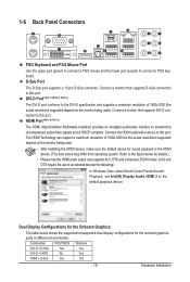
D-Sub Port The D-Sub port supports a 15-pin D-Sub connector. Connect a monitor that supports D-Sub connection to this port. Combination POST/BIOS Windows DVI-D + D-Sub Yes Yes DVI-D + HDMI No Yes HDMI + D-Sub Yes Yes - 19 - 1-6 Back Panel Connectors PS/2 Keyboard and PS/2 Mouse Port Use the ...
D-Sub Port The D-Sub port supports a 15-pin D-Sub connector. Connect a monitor that supports D-Sub connection to this port. Combination POST/BIOS Windows DVI-D + D-Sub Yes Yes DVI-D + HDMI No Yes HDMI + D-Sub Yes Yes - 19 - 1-6 Back Panel Connectors PS/2 Keyboard and PS/2 Mouse Port Use the ...

Manual
Page 20
... the LAN port LEDs. Only microphones still MUST be used to the default Mic in jack ( ). Before using this port for output when in the BIOS Setup program or when during the POST screens. • When removing the cable connected to an external audio system that your device and then remove...
... the LAN port LEDs. Only microphones still MUST be used to the default Mic in jack ( ). Before using this port for output when in the BIOS Setup program or when during the POST screens. • When removing the cable connected to an external audio system that your device and then remove...
Manual
Page 25
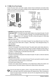
.... Message/Power/ Power Sleep LED Switch Speaker MSG+ MSG- One single short beep will be heard if no problem is detected, the BIOS may issue beeps in S1 sleep state. Refer to Chapter 5, "Troubleshooting," for more information). • SPEAK (Speaker, Orange): Connects ...S1 Blinking tem is operating. If a problem is detected at system startup. When connecting your system using the power switch (refer to Chapter 2, "BIOS Setup," "Power Management Setup," for information about beep codes. • HD (Hard Drive Activity LED, Blue) Connects to indicate the problem. PW...
.... Message/Power/ Power Sleep LED Switch Speaker MSG+ MSG- One single short beep will be heard if no problem is detected, the BIOS may issue beeps in S1 sleep state. Refer to Chapter 5, "Troubleshooting," for more information). • SPEAK (Speaker, Orange): Connects ...S1 Blinking tem is operating. If a problem is detected at system startup. When connecting your system using the power switch (refer to Chapter 2, "BIOS Setup," "Power Management Setup," for information about beep codes. • HD (Hard Drive Activity LED, Blue) Connects to indicate the problem. PW...

Manual
Page 29
... For purchasing the optional COM port cable, please contact the local dealer. Hardware Installation date information and BIOS configurations) and reset the CMOS values to touch the two pins for BIOS configurations). - 29 - Failure to do so may cause damage to the motherboard. • After ...system restart, go to BIOS Setup to load factory defaults (select Load Optimized Defaults) or manually configure the BIOS settings (refer to remove the jumper cap from the power outlet before clearing the CMOS values. •...
... For purchasing the optional COM port cable, please contact the local dealer. Hardware Installation date information and BIOS configurations) and reset the CMOS values to touch the two pins for BIOS configurations). - 29 - Failure to do so may cause damage to the motherboard. • After ...system restart, go to BIOS Setup to load factory defaults (select Load Optimized Defaults) or manually configure the BIOS settings (refer to remove the jumper cap from the power outlet before clearing the CMOS values. •...
Manual
Page 30
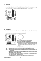
... with local environmental regulations. The higher the CPU loading, the more details. 18) BAT (Battery) The battery provides power to keep the values (such as BIOS configurations, date, and time information) in the power cord and restart your computer. • Always turn off your computer and unplug the power cord before...
... with local environmental regulations. The higher the CPU loading, the more details. 18) BAT (Battery) The battery provides power to keep the values (such as BIOS configurations, date, and time information) in the power cord and restart your computer. • Always turn off your computer and unplug the power cord before...
Manual
Page 31
... basic system configuration settings or to activate certain system features. To upgrade the BIOS, use either the GIGABYTE Q-Flash or @BIOS utility. • Q-Flash allows the user to quickly and easily upgrade or back up BIOS without entering the operating system. • @BIOS is potentially risky, if you need to) to prevent system instability or...
... basic system configuration settings or to activate certain system features. To upgrade the BIOS, use either the GIGABYTE Q-Flash or @BIOS utility. • Q-Flash allows the user to quickly and easily upgrade or back up BIOS without entering the operating system. • @BIOS is potentially risky, if you need to) to prevent system instability or...

Manual
Page 32
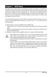
EG41MFT-US2H F5a . . . . : BIOS Setup : XpressRecovery2 : Boot Menu : Qflash 08/16/2010-G41-ICH7-6A79PG02C-00 Function Keys Function Keys: : BIOS SETUP Press the key to enter BIOS Setup or to access the Q-Flash utility in BIOS Setup. : XPRESS RECOVERY2 If you to set the first boot device without having to accept. ... screens may appear when the computer boots. The system will still be used for one time only. Note: The setting in Boot Menu. BIOS Setup - 32 - To exit Boot Menu, press . After system restart, the device boot order will directly boot from the device configured ...
EG41MFT-US2H F5a . . . . : BIOS Setup : XpressRecovery2 : Boot Menu : Qflash 08/16/2010-G41-ICH7-6A79PG02C-00 Function Keys Function Keys: : BIOS SETUP Press the key to enter BIOS Setup or to access the Q-Flash utility in BIOS Setup. : XPRESS RECOVERY2 If you to set the first boot device without having to accept. ... screens may appear when the computer boots. The system will still be used for one time only. Note: The setting in Boot Menu. BIOS Setup - 32 - To exit Boot Menu, press . After system restart, the device boot order will directly boot from the device configured ...
Manual
Page 33
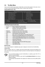
... the submenu. • If you do not find the settings you enter the BIOS Setup program, the Main Menu (as usual, select the Load Optimized Defaults item to set your system ...Select Item F10: Save & Exit Setup Change CPU's Clock & Voltage F11: Save CMOS to BIOS F12: Load CMOS from BIOS BIOS Setup Program Function Keys Move the selection bar to select an item Execute command or enter the ...submenu Main Menu: Exit the BIOS Setup program Submenus: Exit current submenu Increase the numeric value or make changes Decrease ...
... the submenu. • If you do not find the settings you enter the BIOS Setup program, the Main Menu (as usual, select the Load Optimized Defaults item to set your system ...Select Item F10: Save & Exit Setup Change CPU's Clock & Voltage F11: Save CMOS to BIOS F12: Load CMOS from BIOS BIOS Setup Program Function Keys Move the selection bar to select an item Execute command or enter the ...submenu Main Menu: Exit the BIOS Setup program Submenus: Exit current submenu Increase the numeric value or make changes Decrease ...
Manual
Page 34
.../PCI Configurations Use this menu to configure the system's PCI & PnP resources. PC Health Status Use this function to load the BIOS settings from BIOS If your CPU, memory, etc. Standard CMOS Features Use this menu to configure the system time and date, hard drive types,... to configure advanced features available on the chipset. Integrated Peripherals Use this menu to configure all changes and the previous settings remain in BIOS Setup. Set User Password Change, set , or disable password. It allows you to restrict access to make changes. Save...
.../PCI Configurations Use this menu to configure the system's PCI & PnP resources. PC Health Status Use this function to load the BIOS settings from BIOS If your CPU, memory, etc. Standard CMOS Features Use this menu to configure the system time and date, hard drive types,... to configure advanced features available on the chipset. Integrated Peripherals Use this menu to configure all changes and the previous settings remain in BIOS Setup. Set User Password Change, set , or disable password. It allows you to restrict access to make changes. Save...
Manual
Page 35
BIOS Setup If this occurs, clear the CMOS values and reset the board to CPU, chipset, or memory and reduce the useful life of these components. 2-3 ...
BIOS Setup If this occurs, clear the CMOS values and reset the board to CPU, chipset, or memory and reduce the useful life of these components. 2-3 ...
Manual
Page 36
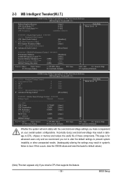
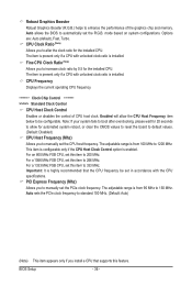
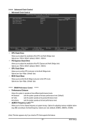
For a 1066 MHz FSB CPU, set this feature. PCI Express Frequency (Mhz) Allows you to automatically set the PCIe clock frequency. Auto allows the BIOS to manually set the R.G.B. Fine CPU Clock Ratio (Note) Allows you to manually set in accordance with the CPU specifications. CPU Frequency Displays the current ..., Turbo. Robust Graphics Booster Robust Graphics Booster (R.G.B.) helps to 1200 MHz. This item is configurable only if the CPU Host Clock Control option is installed. BIOS Setup - 36 -
For a 1066 MHz FSB CPU, set this feature. PCI Express Frequency (Mhz) Allows you to automatically set the PCIe clock frequency. Auto allows the BIOS to manually set the R.G.B. Fine CPU Clock Ratio (Note) Allows you to manually set in accordance with the CPU specifications. CPU Frequency Displays the current ..., Turbo. Robust Graphics Booster Robust Graphics Booster (R.G.B.) helps to 1200 MHz. This item is configurable only if the CPU Host Clock Control option is installed. BIOS Setup - 36 -
Manual
Page 37
... PCI Express and North Bridge clock. Extreme Lets the system operate at three different performance levels. CPU Clock Skew Allows you to the fixed frequency. BIOS Setup Standard Lets the system operate at its basic performance level. (Default) Turbo Lets the system operate at system bootup.
... PCI Express and North Bridge clock. Extreme Lets the system operate at three different performance levels. CPU Clock Skew Allows you to the fixed frequency. BIOS Setup Standard Lets the system operate at its basic performance level. (Default) Turbo Lets the system operate at system bootup.
Manual
Page 38
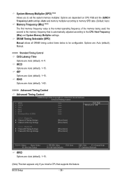
...: Select F5: Previous Values +/-/PU/PD: Value F10: Save F6: Fail-Safe Defaults tRRD Options are : Auto (default), 1~15. tRCD Options are : Auto (default), 4~11. BIOS Setup - 38 - Options are: Auto (default), Manual. >>>>> Standard Timing Control CAS Latency Time Options are : Auto (default), 1~15. DRAM Timing Selectable (SPD) Manual allows all...
...: Select F5: Previous Values +/-/PU/PD: Value F10: Save F6: Fail-Safe Defaults tRRD Options are : Auto (default), 1~15. tRCD Options are : Auto (default), 4~11. BIOS Setup - 38 - Options are: Auto (default), Manual. >>>>> Standard Timing Control CAS Latency Time Options are : Auto (default), 1~15. DRAM Timing Selectable (SPD) Manual allows all...


