
Manual
Page 1
GA-EG41MFT-US2H LGA775 socket motherboard for Intel® Core™ processor family/ Intel® Pentium® processor family/Intel® Celeron® processor family User's Manual Rev. 1301 12ME-EG41FT2-1301R
GA-EG41MFT-US2H LGA775 socket motherboard for Intel® Core™ processor family/ Intel® Pentium® processor family/Intel® Celeron® processor family User's Manual Rev. 1301 12ME-EG41FT2-1301R

Manual
Page 2
Motherboard GA-EG41MFT-US2H Sept. 17, 2009 Motherboard GA-EG41MFT-US2H Sept. 17, 2009
Motherboard GA-EG41MFT-US2H Sept. 17, 2009 Motherboard GA-EG41MFT-US2H Sept. 17, 2009
Manual
Page 3
... User's Manual. For instructions on how to the specifications and features in this manual may be made by GIGABYTE without GIGABYTE's prior written permission. For product-related information, check on our website at: http://www.gigabyte.com Identifying Your Motherboard Revision The revision number on our website. Changes to use of this product...
... User's Manual. For instructions on how to the specifications and features in this manual may be made by GIGABYTE without GIGABYTE's prior written permission. For product-related information, check on our website at: http://www.gigabyte.com Identifying Your Motherboard Revision The revision number on our website. Changes to use of this product...

Manual
Page 4
Table of Contents Box Contents...6 Optional Items...6 GA-EG41MFT-US2H Motherboard Layout 7 GA-EG41MFT-US2H Motherboard Block Diagram 8 Chapter 1 Hardware Installation 9 1-1 Installation Precautions 9 1-2 Product Specifications 10 1-3 Installing the CPU and CPU Cooler 13 1-3-1 Installing the CPU 13 1-3-2 Installing the CPU Cooler ...
Table of Contents Box Contents...6 Optional Items...6 GA-EG41MFT-US2H Motherboard Layout 7 GA-EG41MFT-US2H Motherboard Block Diagram 8 Chapter 1 Hardware Installation 9 1-1 Installation Precautions 9 1-2 Product Specifications 10 1-3 Installing the CPU and CPU Cooler 13 1-3-1 Installing the CPU 13 1-3-2 Installing the CPU Cooler ...
Manual
Page 6
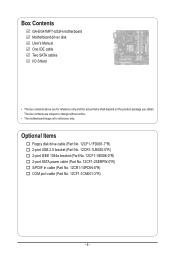
...-1IE008-0*R) 2-port SATA power cable (Part No. 12CF1-2SERPW-0*R) S/PDIF In cable (Part No. 12CR1-1SPDIN-0*R) COM port cable (Part No. 12CF1-1CM001-3*R) - 6 - Box Contents GA-EG41MFT-US2H motherboard Motherboard driver disk User's Manual One IDE cable Two SATA cables I/O Shield • The box contents above are subject to change without notice. • The...
...-1IE008-0*R) 2-port SATA power cable (Part No. 12CF1-2SERPW-0*R) S/PDIF In cable (Part No. 12CR1-1SPDIN-0*R) COM port cable (Part No. 12CF1-1CM001-3*R) - 6 - Box Contents GA-EG41MFT-US2H motherboard Motherboard driver disk User's Manual One IDE cable Two SATA cables I/O Shield • The box contents above are subject to change without notice. • The...

Manual
Page 7
TSB43AB23 SATA2_0 SATA2_2 CLR_CMOS F1_1394 F_USB1 F_USB2 F_PANEL - 7 - GA-EG41MFT-US2H Motherboard Layout KB_MS ATX_12V LGA775 PHASE LED iTE IT8718 VGA LAN DVI GA-EG41MFT-US2H HDMI Level Shifter Level Shifter Optical FDD USB_1394 USB BAT AUDIO F_AUDIO CPU_FAN PCIEX1 Realtek RTL8111D PCIEX16 PCI1 SPDIF_O PCI2 CODEC CD_IN COMA SPDIF_I Intel® G41 B_BIOS M_BIOS DDR3_1 DDR3_2 DDR3_3 DDR3_4 IDE ATX Intel® ICH7 SYS_FAN SATA2_1 SATA2_3 T.I.
TSB43AB23 SATA2_0 SATA2_2 CLR_CMOS F1_1394 F_USB1 F_USB2 F_PANEL - 7 - GA-EG41MFT-US2H Motherboard Layout KB_MS ATX_12V LGA775 PHASE LED iTE IT8718 VGA LAN DVI GA-EG41MFT-US2H HDMI Level Shifter Level Shifter Optical FDD USB_1394 USB BAT AUDIO F_AUDIO CPU_FAN PCIEX1 Realtek RTL8111D PCIEX16 PCI1 SPDIF_O PCI2 CODEC CD_IN COMA SPDIF_I Intel® G41 B_BIOS M_BIOS DDR3_1 DDR3_2 DDR3_3 DDR3_4 IDE ATX Intel® ICH7 SYS_FAN SATA2_1 SATA2_3 T.I.
Manual
Page 8
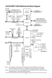
GA-EG41MFT-US2H Motherboard Block Diagram PCIe CLK (100 MHz) 1 PCI Express x16 (Note 1) x8 LGA775 Processor CPU CLK+/(333/266/200 MHz) HDMI(Note 2) DVI-D(Note 2) Switch Switch ...
GA-EG41MFT-US2H Motherboard Block Diagram PCIe CLK (100 MHz) 1 PCI Express x16 (Note 1) x8 LGA775 Processor CPU CLK+/(333/266/200 MHz) HDMI(Note 2) DVI-D(Note 2) Switch Switch ...

Manual
Page 9
... technician. - 9 - These stickers are required for warranty validation. • Always remove the AC power by unplugging the power cord from the motherboard, make sure the power supply has been turned off. • Before turning on the power, make sure they are uncertain about any metal leads... or connectors. • It is best to the internal connectors on the computer power during the installation process can become damaged as a motherboard, CPU or memory. Prior to installation, carefully read the user's manual and follow these procedures: • Prior to installation, do not...
... technician. - 9 - These stickers are required for warranty validation. • Always remove the AC power by unplugging the power cord from the motherboard, make sure the power supply has been turned off. • Before turning on the power, make sure they are uncertain about any metal leads... or connectors. • It is best to the internal connectors on the computer power during the installation process can become damaged as a motherboard, CPU or memory. Prior to installation, carefully read the user's manual and follow these procedures: • Prior to installation, do not...
Manual
Page 12
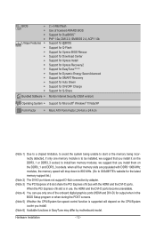
... or when during the POST screens. (Note 5) Whether the CPU/System fan speed control function is supported will drop down to 800 MHz. (Go to GIGABYTE's website for Microsoft® Windows® 7/Vista/XP Form Factor w Micro ATX Form Factor; 24.4cm x 24.4cm (Note 1) Due to a ... Security (OEM version) Operating System w Support for the latest memory support list.) (Note 2) The DVI-D port does not support D-Sub connection by motherboard model. Hardware Installation - 12 - when all four memory slots are populated with DDR3 1066 MHz modules, the memory speed will depend on the CPU/...
... or when during the POST screens. (Note 5) Whether the CPU/System fan speed control function is supported will drop down to 800 MHz. (Go to GIGABYTE's website for Microsoft® Windows® 7/Vista/XP Form Factor w Micro ATX Form Factor; 24.4cm x 24.4cm (Note 1) Due to a ... Security (OEM version) Operating System w Support for the latest memory support list.) (Note 2) The DVI-D port does not support D-Sub connection by motherboard model. Hardware Installation - 12 - when all four memory slots are populated with DDR3 1066 MHz modules, the memory speed will depend on the CPU/...
Manual
Page 13
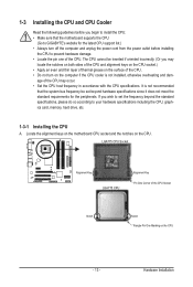
...host frequency in accordance with the CPU specifications. 1-3 Installing the CPU and CPU Cooler Read the following guidelines before installing the CPU to GIGABYTE's website for the peripherals. LGA775 CPU Socket Alignment Key LGA775 CPU Alignment Key Pin One Corner of the CPU. Hardware Installation Locate ...the alignment keys on the motherboard CPU socket and the notches on the CPU - 13 - age of the CPU may locate the notches on both sides of the ...
...host frequency in accordance with the CPU specifications. 1-3 Installing the CPU and CPU Cooler Read the following guidelines before installing the CPU to GIGABYTE's website for the peripherals. LGA775 CPU Socket Alignment Key LGA775 CPU Alignment Key Pin One Corner of the CPU. Hardware Installation Locate ...the alignment keys on the motherboard CPU socket and the notches on the CPU - 13 - age of the CPU may locate the notches on both sides of the ...
Manual
Page 14
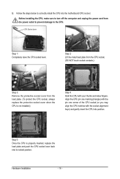
..., always replace the protective socket cover when the CPU is properly inserted, replace the load plate and push the CPU socket lever back into the motherboard CPU socket. CPU Socket Lever Step 1: Completely raise the CPU socket lever. Before installing the CPU, make sure to the CPU. Hardware Installation - 14 - Step...
..., always replace the protective socket cover when the CPU is properly inserted, replace the load plate and push the CPU socket lever back into the motherboard CPU socket. CPU Socket Lever Step 1: Completely raise the CPU socket lever. Before installing the CPU, make sure to the CPU. Hardware Installation - 14 - Step...
Manual
Page 15
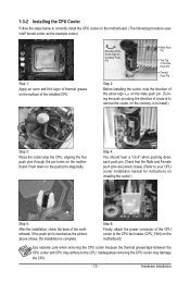
...of the CPU cooler to the CPU fan header (CPU_FAN) on installing the cooler.) Step 5: After the installation, check the back of the motherboard. Inadequately removing the CPU cooler may adhere to the CPU. Push down each push pin. If the push pin is inserted as the example ...CPU cooler and CPU may damage the CPU. - 15 - 1-3-2 Installing the CPU Cooler Follow the steps below to correctly install the CPU cooler on the motherboard. (The following procedure uses Intel® boxed cooler as the picture above shows, the installation is complete. Step 4: You should hear a "click" ...
...of the CPU cooler to the CPU fan header (CPU_FAN) on installing the cooler.) Step 5: After the installation, check the back of the motherboard. Inadequately removing the CPU cooler may adhere to the CPU. Push down each push pin. If the push pin is inserted as the example ...CPU cooler and CPU may damage the CPU. - 15 - 1-3-2 Installing the CPU Cooler Follow the steps below to correctly install the CPU cooler on the motherboard. (The following procedure uses Intel® boxed cooler as the picture above shows, the installation is complete. Step 4: You should hear a "click" ...

Manual
Page 16
... the POST. The four DDR3 memory sockets are unable to insert the memory, switch the direction. 1-4-1 Dual Channel Memory Configuration This motherboard provides four DDR3 memory sockets and supports Dual Channel Technology. DS/SS Four Modules SS SS SS SS (SS=Single-Sided, DS...Go to be installed in Dual Channel mode/performance. Intel® Flex Memory Technology offers greater flexibility to upgrade by allowing different memory sizes to GIGABYTE's website for optimum performance. 3. DS/SS - - - - when all four memory slots are installed, a message which says memory is...
... the POST. The four DDR3 memory sockets are unable to insert the memory, switch the direction. 1-4-1 Dual Channel Memory Configuration This motherboard provides four DDR3 memory sockets and supports Dual Channel Technology. DS/SS Four Modules SS SS SS SS (SS=Single-Sided, DS...Go to be installed in Dual Channel mode/performance. Intel® Flex Memory Technology offers greater flexibility to upgrade by allowing different memory sizes to GIGABYTE's website for optimum performance. 3. DS/SS - - - - when all four memory slots are installed, a message which says memory is...
Manual
Page 17
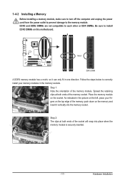
... below to correctly install your fingers on the memory and insert it can only fit in the memory sockets. Place the memory module on this motherboard. Hardware Installation Notch DDR3 DIMM A DDR3 memory module has a notch, so it vertically into place when the memory module is securely inserted. - 17 - 1-4-2 Installing a Memory...
... below to correctly install your fingers on the memory and insert it can only fit in the memory sockets. Place the memory module on this motherboard. Hardware Installation Notch DDR3 DIMM A DDR3 memory module has a notch, so it vertically into place when the memory module is securely inserted. - 17 - 1-4-2 Installing a Memory...

Manual
Page 18
... outlet before you begin to the chassis back panel with a screw. 5. Secure the card's metal bracket to install an expansion card: • Make sure the motherboard supports the expansion card. Make sure the card is fully seated in the expansion slot. 1. Locate an expansion slot that came with the expansion card...
... outlet before you begin to the chassis back panel with a screw. 5. Secure the card's metal bracket to install an expansion card: • Make sure the motherboard supports the expansion card. Make sure the card is fully seated in the expansion slot. 1. Locate an expansion slot that came with the expansion card...

Manual
Page 20
..., etc. Optical S/PDIF Out Connector This connector provides digital audio out to an external audio system that your device and then remove it from the motherboard. • When removing the cable, pull it side to side to 1 Gbps data rate. Connection/ Speed LED Activity LED Connection/Speed LED: State Description Orange...
..., etc. Optical S/PDIF Out Connector This connector provides digital audio out to an external audio system that your device and then remove it from the motherboard. • When removing the cable, pull it side to side to 1 Gbps data rate. Connection/ Speed LED Activity LED Connection/Speed LED: State Description Orange...

Manual
Page 21
..., make sure your devices are compliant with the connectors you wish to connect. • Before installing the devices, be sure to the connector on the motherboard. - 21 -
..., make sure your devices are compliant with the connectors you wish to connect. • Before installing the devices, be sure to the connector on the motherboard. - 21 -
Manual
Page 22
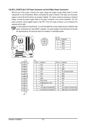
... be used (500W or greater). The power connector possesses a foolproof design. If the 12V power connector is turned off and all the components on the motherboard. Before connecting the power connector, first make sure the power supply is not connected, the computer will not start.
... be used (500W or greater). The power connector possesses a foolproof design. If the 12V power connector is turned off and all the components on the motherboard. Before connecting the power connector, first make sure the power supply is not connected, the computer will not start.
Manual
Page 23
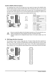
3/4) CPU_FAN/SYS_FAN (Fan Headers) The motherboard has a 4-pin CPU fan header and a 4-pin system fan header (CPU_FAN/SYS_FAN). For optimum heat dissipation, it in damage to connect a floppy disk drive. For ... fan be installed inside the chassis. 1 CPU_FAN CPU_FAN: Pin No. The types of different color. The pin 1 of the cable is the ground wire). The motherboard supports CPU fan speed control, which requires the use of the connector and the floppy disk drive cable. Hardware Installation Overheating may hang. • These...
3/4) CPU_FAN/SYS_FAN (Fan Headers) The motherboard has a 4-pin CPU fan header and a 4-pin system fan header (CPU_FAN/SYS_FAN). For optimum heat dissipation, it in damage to connect a floppy disk drive. For ... fan be installed inside the chassis. 1 CPU_FAN CPU_FAN: Pin No. The types of different color. The pin 1 of the cable is the ground wire). The motherboard supports CPU fan speed control, which requires the use of the connector and the floppy disk drive cable. Hardware Installation Overheating may hang. • These...

Manual
Page 26
... Audio Header) The front panel audio header supports Intel High Definition audio (HD) and AC'97 audio. Incorrect connection between the module connector and the motherboard header will be present on both of a single plug. If you want to mute the back panel audio (only supported when using an HD front...; Audio signals will make the device unable to this header. Make sure the wire assignments of the module connector match the pin assignments of the motherboard header.
... Audio Header) The front panel audio header supports Intel High Definition audio (HD) and AC'97 audio. Incorrect connection between the module connector and the motherboard header will be present on both of a single plug. If you want to mute the back panel audio (only supported when using an HD front...; Audio signals will make the device unable to this header. Make sure the wire assignments of the module connector match the pin assignments of the motherboard header.


