
Manual
Page 3
... download the information on/from the Support\Motherboard\Technology Guide page on your motherboard revision before updating motherboard BIOS, drivers, or when looking for technical information. Disclaimer Information in any form or by GIGABYTE without GIGABYTE's prior written permission. All rights reserved. Changes to the specifications and features in this manual may be...
... download the information on/from the Support\Motherboard\Technology Guide page on your motherboard revision before updating motherboard BIOS, drivers, or when looking for technical information. Disclaimer Information in any form or by GIGABYTE without GIGABYTE's prior written permission. All rights reserved. Changes to the specifications and features in this manual may be...
Manual
Page 4
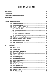
Table of Contents Box Contents ...6 OptionalItems ...6 GA-E7AUM-DS2H Motherboard Layout 7 Block Diagram ...8 Chapter 1 Hardware Installation 9 1-1 Installation Precautions 9 1-2 Product Specifications 10 1-3 Installing the CPU and CPU Cooler 13...the NVIDIA PhysX Function 20 1-8 Back Panel Connectors 21 1-9 Internal Connectors 24 Chapter 2 BIOS Setup 35 2-1 Startup Screen 36 2-2 The Main Menu 37 2-3 MB Intelligent Tweaker(M.I.T 39 2-4 Standard CMOS Features 42 2-5 Advanced BIOS Features 44 2-6 IntegratedPeripherals 48 2-7 Power Management Setup 51 2-8 PnP/PCI Configurations 53 ...
Table of Contents Box Contents ...6 OptionalItems ...6 GA-E7AUM-DS2H Motherboard Layout 7 Block Diagram ...8 Chapter 1 Hardware Installation 9 1-1 Installation Precautions 9 1-2 Product Specifications 10 1-3 Installing the CPU and CPU Cooler 13...the NVIDIA PhysX Function 20 1-8 Back Panel Connectors 21 1-9 Internal Connectors 24 Chapter 2 BIOS Setup 35 2-1 Startup Screen 36 2-2 The Main Menu 37 2-3 MB Intelligent Tweaker(M.I.T 39 2-4 Standard CMOS Features 42 2-5 Advanced BIOS Features 44 2-6 IntegratedPeripherals 48 2-7 Power Management Setup 51 2-8 PnP/PCI Configurations 53 ...

Manual
Page 5
... 60 3-3 Technical Manuals 60 3-4 Contact ...61 3-5 System ...61 3-6 Download Center 62 Chapter 4 Unique Features 63 4-1 Xpress Recovery2 63 4-2 BIOS Update Utilities 68 4-2-1 Updating the BIOS with the Q-Flash Utility 68 4-2-2 Updating the BIOS with the @BIOS Utility 71 4-3 EasyTune 6 ...72 4-4 Dynamic Energy Saver Advanced 73 4-5 Q-Share ...75 4-6 Time Repair ...76 Chapter 5 Appendix ...77 5-1 Configuring...
... 60 3-3 Technical Manuals 60 3-4 Contact ...61 3-5 System ...61 3-6 Download Center 62 Chapter 4 Unique Features 63 4-1 Xpress Recovery2 63 4-2 BIOS Update Utilities 68 4-2-1 Updating the BIOS with the Q-Flash Utility 68 4-2-2 Updating the BIOS with the @BIOS Utility 71 4-3 EasyTune 6 ...72 4-4 Dynamic Energy Saver Advanced 73 4-5 Q-Share ...75 4-6 Time Repair ...76 Chapter 5 Appendix ...77 5-1 Configuring...

Manual
Page 8
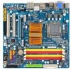
... DDR2 800/667 MHz Dual Channel Memory NVIDIA® GeForce 9400 6 SATA 3Gb/s 12 USB Ports RTL 8211CL LAN RJ45 LPC BUS IT8718 CODEC Dual BIOS Floppy COM Port PS/2 KB or Mouse LPT Port Surround Speaker Out Center/Subwoofer Speaker Out Side Speaker Out MIC Line-Out Line-In SPDIF...
... DDR2 800/667 MHz Dual Channel Memory NVIDIA® GeForce 9400 6 SATA 3Gb/s 12 USB Ports RTL 8211CL LAN RJ45 LPC BUS IT8718 CODEC Dual BIOS Floppy COM Port PS/2 KB or Mouse LPT Port Surround Speaker Out Center/Subwoofer Speaker Out Side Speaker Out MIC Line-Out Line-In SPDIF...
Manual
Page 12
GA-E7AUM-DS2H Motherboard - 12 - BIOS Unique Features Bundled Software Operating System Form Factor 2 x 8 Mbit flash Use of licensed AWARD BIOS Support for DualBIOSTM PnP 1.0a, DMI 2.0, SM BIOS 2.4, ACPI 1.0b Support for @BIOS Support for Q-Flash Support for Virtual Dual BIOS Support for Download Center Support for Xpress Install...
GA-E7AUM-DS2H Motherboard - 12 - BIOS Unique Features Bundled Software Operating System Form Factor 2 x 8 Mbit flash Use of licensed AWARD BIOS Support for DualBIOSTM PnP 1.0a, DMI 2.0, SM BIOS 2.4, ACPI 1.0b Support for @BIOS Support for Q-Flash Support for Virtual Dual BIOS Support for Download Center Support for Xpress Install...
Manual
Page 16
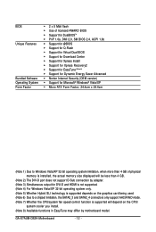
...installing the memory to prevent hardware damage. • Memory modules have a foolproof design. GA-E7AUM-DS2H Motherboard - 16 - When enabling Dual Channel mode with two or four memory modules, ...This motherboard provides four DDR2 memory sockets and supports Dual Channel Technology. If you begin to GIGABYTE's website for optimum performance. The four DDR2 memory sockets are unable to chipset limitation, ... and chips be installed in only one DDR2 memory module is installed, the BIOS will double the original memory bandwidth. 1-4 Installing the Memory Read the following ...
...installing the memory to prevent hardware damage. • Memory modules have a foolproof design. GA-E7AUM-DS2H Motherboard - 16 - When enabling Dual Channel mode with two or four memory modules, ...This motherboard provides four DDR2 memory sockets and supports Dual Channel Technology. If you begin to GIGABYTE's website for optimum performance. The four DDR2 memory sockets are unable to chipset limitation, ... and chips be installed in only one DDR2 memory module is installed, the BIOS will double the original memory bandwidth. 1-4 Installing the Memory Read the following ...
Manual
Page 18
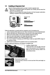
.... 5. Secure the card's metal bracket to install an expansion card: • Make sure the motherboard supports the expansion card. GA-E7AUM-DS2H Motherboard - 18 - If necessary, go to BIOS Setup to make any required BIOS changes for your expansion card. • Always turn off the computer and unplug the power cord from the chassis back...
.... 5. Secure the card's metal bracket to install an expansion card: • Make sure the motherboard supports the expansion card. GA-E7AUM-DS2H Motherboard - 18 - If necessary, go to BIOS Setup to make any required BIOS changes for your expansion card. • Always turn off the computer and unplug the power cord from the chassis back...

Manual
Page 19
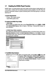
... operating system • Latest NVIDIA graphics driver • System BIOS that the Hybrid SLI-ready graphics card be installed after the motherboard driver installation. BIOS Setup: Enter BIOS Setup to set the following items under the Advanced BIOS Features menu: • Set Hybrid SLI to Auto. •...• Set iGPU Frame Buffer Control to Manual. • Set Frame Buffer Size to 256MB or 512MB. (Refer to Chapter 2, "BIOS Setup", "Advanced BIOS Features", for Hybrid SLI Mode: Click the Hybrid SLI icon to NVIDIA's website for installation. Enabling Hybrid SLI: 1. Restart your mouse...
... operating system • Latest NVIDIA graphics driver • System BIOS that the Hybrid SLI-ready graphics card be installed after the motherboard driver installation. BIOS Setup: Enter BIOS Setup to set the following items under the Advanced BIOS Features menu: • Set Hybrid SLI to Auto. •...• Set iGPU Frame Buffer Control to Manual. • Set Frame Buffer Size to 256MB or 512MB. (Refer to Chapter 2, "BIOS Setup", "Advanced BIOS Features", for Hybrid SLI Mode: Click the Hybrid SLI icon to NVIDIA's website for installation. Enabling Hybrid SLI: 1. Restart your mouse...
Manual
Page 20
A. BIOS Setup: Before installing the NVIDIA PhysX utility, ensure Frame Buffer Size is set to 256MB or 512MB under Hardware Device Selection, it means the NVIDIA ... in leading edge PC and console games. On the Settings tab, if GeForce PhysX has been selected under Advanced BIOS Features. (Refer to a new level delivering rich. Installing the NVIDIA PhysX Utility: 1. C. GA-E7AUM-DS2H Motherboard - 20 - System Requirements: • At least 1 GB of the NVIDIA PhysX Utility. NVIDIA PhysX Utility Installation: After installing...
A. BIOS Setup: Before installing the NVIDIA PhysX utility, ensure Frame Buffer Size is set to 256MB or 512MB under Hardware Device Selection, it means the NVIDIA ... in leading edge PC and console games. On the Settings tab, if GeForce PhysX has been selected under Advanced BIOS Features. (Refer to a new level delivering rich. Installing the NVIDIA PhysX Utility: 1. C. GA-E7AUM-DS2H Motherboard - 20 - System Requirements: • At least 1 GB of the NVIDIA PhysX Utility. NVIDIA PhysX Utility Installation: After installing...
Manual
Page 22
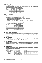
Playback of Frame Buffer Size (refer to Chapter 2, "BIOS Setup," "Advanced BIOS Features," for more information) • Playback software: CyberLink PowerDVD 8.0 File Format Suitable Resolution Windows XP Windows Vista Non-protected contents 1920 x 1080p 1920 x 1080p HD-...; Memory: 1 GB of DDR2 800 memory • BIOS Setup: At least 256 MB of HD DVD and Blu-ray Discs: In order to get better playback quality, when playing the HD DVD or Blu-ray discs, refer to SATA 3Gb/s standard and is occurring GA-E7AUM-DS2H Motherboard - 22 - The following describes the states...
Playback of Frame Buffer Size (refer to Chapter 2, "BIOS Setup," "Advanced BIOS Features," for more information) • Playback software: CyberLink PowerDVD 8.0 File Format Suitable Resolution Windows XP Windows Vista Non-protected contents 1920 x 1080p 1920 x 1080p HD-...; Memory: 1 GB of DDR2 800 memory • BIOS Setup: At least 256 MB of HD DVD and Blu-ray Discs: In order to get better playback quality, when playing the HD DVD or Blu-ray discs, refer to SATA 3Gb/s standard and is occurring GA-E7AUM-DS2H Motherboard - 22 - The following describes the states...
Manual
Page 28
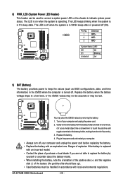
...3 MPD- System Status LED S0 On S1 Blinking S3/S4/S5 Off 9) BAT (Battery) The battery provides power to keep the values (such as BIOS configurations, date, and time information) in accordance with an equivalent one minute. (Or use a metal object like a screwdriver to a low level, or... the orientation of the positive side (+) and the negative side (-) of the battery holder, making them short for one . Pin No. GA-E7AUM-DS2H Motherboard - 28 - Replace the battery when the battery voltage drops to touch the positive and negative terminals of the battery (the positive side...
...3 MPD- System Status LED S0 On S1 Blinking S3/S4/S5 Off 9) BAT (Battery) The battery provides power to keep the values (such as BIOS configurations, date, and time information) in accordance with an equivalent one minute. (Or use a metal object like a screwdriver to a low level, or... the orientation of the positive side (+) and the negative side (-) of the battery holder, making them short for one . Pin No. GA-E7AUM-DS2H Motherboard - 28 - Replace the battery when the battery voltage drops to touch the positive and negative terminals of the battery (the positive side...

Manual
Page 29
...• RES (Reset Switch, Green): Connects to indicate the problem. The LED is on when the hard drive is detected, the BIOS may issue beeps in different patterns to the reset switch on the chassis front panel. The system reports system startup status by chassis. Note... the positive and negative pins before connecting the cables. When connecting your system using the power switch (refer to Chapter 2, "BIOS Setup," "Power Management Setup," for information about beep codes. • HD (Hard Drive Activity LED, Blue) Connects to the power status ...
...• RES (Reset Switch, Green): Connects to indicate the problem. The LED is on when the hard drive is detected, the BIOS may issue beeps in different patterns to the reset switch on the chassis front panel. The system reports system startup status by chassis. Note... the positive and negative pins before connecting the cables. When connecting your system using the power switch (refer to Chapter 2, "BIOS Setup," "Power Management Setup," for information about beep codes. • HD (Hard Drive Activity LED, Blue) Connects to the power status ...

Manual
Page 33
... to the motherboard. • After system restart, go to BIOS Setup to load factory defaults (select Load Optimized Defaults) or manually configure the BIOS settings (refer to Chapter 2, "BIOS Setup," for a few seconds. Hardware Installation date information and BIOS configurations) and reset the CMOS values to clear the CMOS values...the jumper. To clear the CMOS values, place a jumper cap on your computer, be sure to touch the two pins for BIOS configurations). - 33 - 17) LPT (Parallel Port Header) The LPT header can provide one parallel port via an optional LPT port cable.
... to the motherboard. • After system restart, go to BIOS Setup to load factory defaults (select Load Optimized Defaults) or manually configure the BIOS settings (refer to Chapter 2, "BIOS Setup," for a few seconds. Hardware Installation date information and BIOS configurations) and reset the CMOS values to clear the CMOS values...the jumper. To clear the CMOS values, place a jumper cap on your computer, be sure to touch the two pins for BIOS configurations). - 33 - 17) LPT (Parallel Port Header) The LPT header can provide one parallel port via an optional LPT port cable.

Manual
Page 35
To upgrade the BIOS, use either the GIGABYTE Q-Flash or @BIOS utility. • Q-Flash allows the user to quickly and easily upgrade or back up BIOS without entering the operating system. • @BIOS is turned off, the battery on . If this occurs, try to clear the CMOS values and reset the board ... in Chapter 1 for the beep codes description. • It is recommended that searches and downloads the latest version of BIOS from the Internet and updates the BIOS. BIOS Setup When the power is a Windows-based utility that you not alter the default settings (unless you need to) to...
To upgrade the BIOS, use either the GIGABYTE Q-Flash or @BIOS utility. • Q-Flash allows the user to quickly and easily upgrade or back up BIOS without entering the operating system. • @BIOS is turned off, the battery on . If this occurs, try to clear the CMOS values and reset the board ... in Chapter 1 for the beep codes description. • It is recommended that searches and downloads the latest version of BIOS from the Internet and updates the BIOS. BIOS Setup When the power is a Windows-based utility that you not alter the default settings (unless you need to) to...
Manual
Page 36
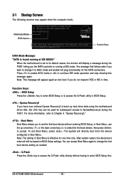
..., refer to its default values, the monitor will appear again at IDE mode. The system will still be used for one time only. GA-E7AUM-DS2H Motherboard - 36 - To exit Boot Menu, press . When the motherboard is found running at next boot if you to set to Chapter...Menu Boot Menu allows you do not respond YES or NO in Boot Menu. Motherboard Model BIOS Version Award Modular BIOS v6.00PG, An Energy Star Ally Copyright (C) 1984-2008, Award Software, Inc. GA-E7AUM-DS2H D22 . . . . : BIOS Setup : XpressRecovery2 : Boot Menu : Qflash 10/07/2008-MCP7A-7A610G01C-00 Function Keys ...
..., refer to its default values, the monitor will appear again at IDE mode. The system will still be used for one time only. GA-E7AUM-DS2H Motherboard - 36 - To exit Boot Menu, press . When the motherboard is found running at next boot if you to set to Chapter...Menu Boot Menu allows you do not respond YES or NO in Boot Menu. Motherboard Model BIOS Version Award Modular BIOS v6.00PG, An Energy Star Ally Copyright (C) 1984-2008, Award Software, Inc. GA-E7AUM-DS2H D22 . . . . : BIOS Setup : XpressRecovery2 : Boot Menu : Qflash 10/07/2008-MCP7A-7A610G01C-00 Function Keys ...

Manual
Page 37
...(as usual, select the Load Optimized Defaults item to set your system to display a help screen. Press to BIOS Load CMOS from BIOS Change CPU's Clock & Voltage BIOS Setup Program Function Keys Move the selection bar to select an item Execute command or enter the submenu Main Menu:... Defaults Load Optimized Defaults Set Supervisor Password Set User Password Save & Exit Setup Exit Without Saving F11: Save CMOS to BIOS F12: Load CMOS from BIOS Main Menu Help The onscreen description of a highlighted setup option is in this chapter are for the current submenus Access the...
...(as usual, select the Load Optimized Defaults item to set your system to display a help screen. Press to BIOS Load CMOS from BIOS Change CPU's Clock & Voltage BIOS Setup Program Function Keys Move the selection bar to select an item Execute command or enter the submenu Main Menu:... Defaults Load Optimized Defaults Set Supervisor Password Set User Password Save & Exit Setup Exit Without Saving F11: Save CMOS to BIOS F12: Load CMOS from BIOS Main Menu Help The onscreen description of a highlighted setup option is in this chapter are for the current submenus Access the...

Manual
Page 38
...; Set Supervisor Password Change, set , or disable password. A supervisor password allows you to the system and BIOS Setup. You can create up to the CMOS and exit BIOS Setup. (Pressing can also carry out this task.) GA-E7AUM-DS2H Motherboard - 38 - It allows you to restrict access to a profile. The Functions of the and...
...; Set Supervisor Password Change, set , or disable password. A supervisor password allows you to the system and BIOS Setup. You can create up to the CMOS and exit BIOS Setup. (Pressing can also carry out this task.) GA-E7AUM-DS2H Motherboard - 38 - It allows you to restrict access to a profile. The Functions of the and...
Manual
Page 39
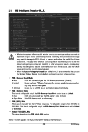
... Exit F1: General Help F7: Optimized Defaults • Whether the system will work stably with the FSB speed. FSB - BIOS Setup Memory Clock Mode Auto BIOS will automatically set FSB speed and memory speed individually. the memory speed changes proportion- Memory Ratio This item is configurable only if...the FSB-Memory Clock Mode option is from 400 MHz to CPU, chipset, or memory and reduce the useful life of these components. Auto BIOS will automatically set the FSB-Memory clock mode. (Default) Linked Allows you to set the FSB-Memory ratio. (Default) Sync Mode Sets...
... Exit F1: General Help F7: Optimized Defaults • Whether the system will work stably with the FSB speed. FSB - BIOS Setup Memory Clock Mode Auto BIOS will automatically set FSB speed and memory speed individually. the memory speed changes proportion- Memory Ratio This item is configurable only if...the FSB-Memory Clock Mode option is from 400 MHz to CPU, chipset, or memory and reduce the useful life of these components. Auto BIOS will automatically set the FSB-Memory clock mode. (Default) Linked Allows you to set the FSB-Memory ratio. (Default) Sync Mode Sets...

Manual
Page 41
... chipset voltage as required. (Default) +0.1V ~ +0.2V Increases chipset voltage by 0.1V to alter the core clock for the installed CPU. BIOS Setup tREF Options are : Auto (default), 1~15. The adjustable range is dependent on the CPU being installed. (Default: Normal) Note: ... voltage as required. (Default) Increases FSB voltage by 1% ~ 50%. tWTR Options are : Auto (default), 7.8uS, 3.9uS. Auto lets BIOS automatically set the CPU voltage. Normal CPU Vcore Displays the normal operating voltage of the chipset. Normal +0.1V ~ +0.3V Supplies the FSB voltage ...
... chipset voltage as required. (Default) +0.1V ~ +0.2V Increases chipset voltage by 0.1V to alter the core clock for the installed CPU. BIOS Setup tREF Options are : Auto (default), 1~15. The adjustable range is dependent on the CPU being installed. (Default: Normal) Note: ... voltage as required. (Default) Increases FSB voltage by 1% ~ 50%. tWTR Options are : Auto (default), 7.8uS, 3.9uS. Auto lets BIOS automatically set the CPU voltage. Normal CPU Vcore Displays the normal operating voltage of the chipset. Normal +0.1V ~ +0.3V Supplies the FSB voltage ...
Manual
Page 42
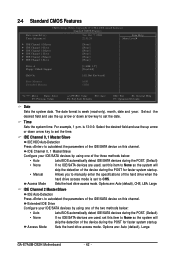
Sets the hard drive access mode. GA-E7AUM-DS2H Motherboard - 42 - IDE Channel 0, 1 Master/Slave IDE HDD Auto-...Channel 0, 1 Master/Slave Configure your IDE/SATA devices by using one of the three methods below : • Auto Lets BIOS automatically detect IDE/SATA devices during the POST. (Default) • None If no IDE/SATA devices are used , set ...by using one of the two methods below : • Auto • None • Manual Access Mode Lets BIOS automatically detect IDE/SATA devices during the POST. (Default) If no IDE/SATA devices are used , set this...
Sets the hard drive access mode. GA-E7AUM-DS2H Motherboard - 42 - IDE Channel 0, 1 Master/Slave IDE HDD Auto-...Channel 0, 1 Master/Slave Configure your IDE/SATA devices by using one of the three methods below : • Auto Lets BIOS automatically detect IDE/SATA devices during the POST. (Default) • None If no IDE/SATA devices are used , set ...by using one of the two methods below : • Auto • None • Manual Access Mode Lets BIOS automatically detect IDE/SATA devices during the POST. (Default) If no IDE/SATA devices are used , set this...


