
Manual
Page 4
... Contents ItemChecklist ...6 OptionalAccessories ...6 GA-945GZM-S2 Motherboard Layout 7 Block Diagram ...8 Chapter 1 Hardware Installation 9 1-1 Considerations Prior to Installation 9 1-2 Feature Summary 10 1-3 Installation of the CPU and CPU Cooler 12 1-3-1 Installation of the CPU 12 1-3-2 Installation of the CPU Cooler 13 1-4 Installation of Memory 14 1-5 Installation of Expansion Cards 15 1-6 I/O Back Panel Introduction 17 1-7 Connectors Introduction...
... Contents ItemChecklist ...6 OptionalAccessories ...6 GA-945GZM-S2 Motherboard Layout 7 Block Diagram ...8 Chapter 1 Hardware Installation 9 1-1 Considerations Prior to Installation 9 1-2 Feature Summary 10 1-3 Installation of the CPU and CPU Cooler 12 1-3-1 Installation of the CPU 12 1-3-2 Installation of the CPU Cooler 13 1-4 Installation of Memory 14 1-5 Installation of Expansion Cards 15 1-6 I/O Back Panel Introduction 17 1-7 Connectors Introduction...
Manual
Page 10
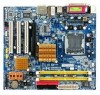
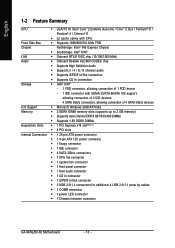
... Š 4 SATA 3Gb/s connectors Š 1 CPU fan connector Š 1 system fan connector Š 1 front panel connector Š 1 front audio connector Š 1 CD In connector Š 1 S/PDIF In/Out connector Š 2 USB 2.0/1.1 connectors for additional 4 USB 2.0/1.1 ports by cables Š 1 COMB connector Š 1 power LED connector Š 1 Chassis Intrusion connector GA-945GZM-S2 Motherboard - 10 -
... Š 4 SATA 3Gb/s connectors Š 1 CPU fan connector Š 1 system fan connector Š 1 front panel connector Š 1 front audio connector Š 1 CD In connector Š 1 S/PDIF In/Out connector Š 2 USB 2.0/1.1 connectors for additional 4 USB 2.0/1.1 ports by cables Š 1 COMB connector Š 1 power LED connector Š 1 Chassis Intrusion connector GA-945GZM-S2 Motherboard - 10 -
Manual
Page 11
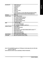
Hardware Installation English Rear Panel I/O Š 1 PS/2 keyboard port Š 1 PS/2 mouse port Š 1 parallel port Š 1 VGA port Š 1 serial port Š 4 USB 2.0/1.1 ports Š 1 RJ-45 port Š 6 ...; Supports Xpress BIOS Rescue Bundle Software Š Norton Internet Security (OEM version) Form Factor Š Micro ATX form factor; 24.4cm x 22.0cm (Note 1) The GA-945GZM-S2 supports up to PCI Express x4 mode. (please refer to the VGA cards support list on page 16) (Note 2) EasyTune functions may vary depending on...
Hardware Installation English Rear Panel I/O Š 1 PS/2 keyboard port Š 1 PS/2 mouse port Š 1 parallel port Š 1 VGA port Š 1 serial port Š 4 USB 2.0/1.1 ports Š 1 RJ-45 port Š 6 ...; Supports Xpress BIOS Rescue Bundle Software Š Norton Internet Security (OEM version) Form Factor Š Micro ATX form factor; 24.4cm x 22.0cm (Note 1) The GA-945GZM-S2 supports up to PCI Express x4 mode. (please refer to the VGA cards support list on page 16) (Note 2) EasyTune functions may vary depending on...
Manual
Page 17
have a standard USB interface. If your OS or device(s) vendors. Rear surround speakers can be connected to Line In jack. Hardware Installation English 1-6 I/O Back Panel Introduction PS/2 Keyboard and PS/2 Mouse Connector To install a PS/2 port keyboard and mouse, plug the mouse to the upper port (green) and the keyboard ...
have a standard USB interface. If your OS or device(s) vendors. Rear surround speakers can be connected to Line In jack. Hardware Installation English 1-6 I/O Back Panel Introduction PS/2 Keyboard and PS/2 Mouse Connector To install a PS/2 port keyboard and mouse, plug the mouse to the upper port (green) and the keyboard ...
Manual
Page 22
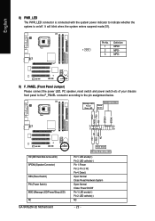
...connector is on/off. Definition 1 MPD+ 1 2 MPD- 3 MPD- 9) F_PANEL (Front Panel Jumper) Please connect the power LED, PC speaker, reset switch and power switch etc of your chassis front panel to the F_PANEL connector according to indicate whether the system is connected with the system power... NC HD (IDE Hard Disk Active LED) SPEAK (Speaker Connector) RES (Reset Switch) PW (Power Switch) MSG (Message LED/Power/Sleep LED) NC GA-945GZM-S2 Motherboard Reset Switch IDE Hard Disk Active LED Pin 1: LED anode(+) Pin 2: LED cathode(-) Pin 1: Power Pin 2- PW+ PWSPEAK+ SPEAK- 2 20 ...
...connector is on/off. Definition 1 MPD+ 1 2 MPD- 3 MPD- 9) F_PANEL (Front Panel Jumper) Please connect the power LED, PC speaker, reset switch and power switch etc of your chassis front panel to the F_PANEL connector according to indicate whether the system is connected with the system power... NC HD (IDE Hard Disk Active LED) SPEAK (Speaker Connector) RES (Reset Switch) PW (Power Switch) MSG (Message LED/Power/Sleep LED) NC GA-945GZM-S2 Motherboard Reset Switch IDE Hard Disk Active LED Pin 1: LED anode(+) Pin 2: LED cathode(-) Pin 1: Power Pin 2- PW+ PWSPEAK+ SPEAK- 2 20 ...
Manual
Page 23
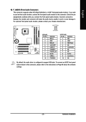
... module. Check the pin assignments carefully while you wish to use the front audio function, connect the front panel audio module to work or even damage it. For optional front panel audio module, please contact your chassis manufacturer. 10 9 2 1 HD Audio: Pin No. 1 2 3 4 5 6 7 8 9 10 Definition MIC2_L ... the audio driver is configured to the instructions on Page 66 about the software settings. - 23 - To connect an AC97 front panel audio module to this connector. English 10) F_AUDIO (Front Audio Connector) This connector supports either HD (High Definition) or AC97 front...
... module. Check the pin assignments carefully while you wish to use the front audio function, connect the front panel audio module to work or even damage it. For optional front panel audio module, please contact your chassis manufacturer. 10 9 2 1 HD Audio: Pin No. 1 2 3 4 5 6 7 8 9 10 Definition MIC2_L ... the audio driver is configured to the instructions on Page 66 about the software settings. - 23 - To connect an AC97 front panel audio module to this connector. English 10) F_AUDIO (Front Audio Connector) This connector supports either HD (High Definition) or AC97 front...

Manual
Page 55
... page 3. "Easy Mode" & "Advance Mode" Toggles between Easy and Advance Mode 7. Featuring several powerful yet easy to GIGABYTE website 10. C.I .B. GO Confirmation and Execution button 6. Function display LEDs Shows the current functions status 9. Help button Display...Description 1. PC Health Enters the PC Health setting page 5. Display screen Display panel of both CPU cooling fan and North-Bridge Chipset cooling fan, 4) PC health for enhancing system performance, 2) C.I .B. GIGABYTE Logo Log on different motherboards. - 55 - for special enhancement for CPU and...
... page 3. "Easy Mode" & "Advance Mode" Toggles between Easy and Advance Mode 7. Featuring several powerful yet easy to GIGABYTE website 10. C.I .B. GO Confirmation and Execution button 6. Function display LEDs Shows the current functions status 9. Help button Display...Description 1. PC Health Enters the PC Health setting page 5. Display screen Display panel of both CPU cooling fan and North-Bridge Chipset cooling fan, 4) PC health for enhancing system performance, 2) C.I .B. GIGABYTE Logo Log on different motherboards. - 55 - for special enhancement for CPU and...
Manual
Page 62
... and multi-streaming applications, HD Audio is able to handle multiple audio streams (in your system tray (you can also find the icon in Control Panel). STEP 1 : After installation of the audio driver, you MUST connect it to the default Mic In jack for the 6 audio jacks are as... the function. (Following pictures are in the picture to MP3 music, have an Internet chat, make a telephone call over the Internet, and etc. GA-945GZM-S2 Motherboard - 62 - HD Audio With multiple built-in high quality digital-to-analog converters (DACs) that you use the speaker with amplifier to acquire ...
... and multi-streaming applications, HD Audio is able to handle multiple audio streams (in your system tray (you can also find the icon in Control Panel). STEP 1 : After installation of the audio driver, you MUST connect it to the default Mic In jack for the 6 audio jacks are as... the function. (Following pictures are in the picture to MP3 music, have an Internet chat, make a telephone call over the Internet, and etc. GA-945GZM-S2 Motherboard - 62 - HD Audio With multiple built-in high quality digital-to-analog converters (DACs) that you use the speaker with amplifier to acquire ...
Manual
Page 63
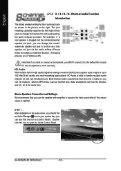
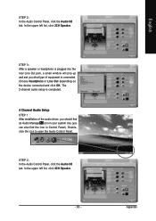
The 2-channel audio setup is connected. STEP 2: In the Audio Control Panel, click the Audio I /O tab. In the upper left list, click 4CH Speaker. - 63 - STEP 3: After a speaker or headphone is plugged into the rear Line Out ... driver, you should find an Audio Manager icon in your system tray (you can also find the icon in Control Panel). Appendix English Doubleclick the icon to open the Audio Control Panel. In the upper left list, click 2CH Speaker. Choose Headphone or Line Out depending on the device connected and click...
The 2-channel audio setup is connected. STEP 2: In the Audio Control Panel, click the Audio I /O tab. In the upper left list, click 4CH Speaker. - 63 - STEP 3: After a speaker or headphone is plugged into the rear Line Out ... driver, you should find an Audio Manager icon in your system tray (you can also find the icon in Control Panel). Appendix English Doubleclick the icon to open the Audio Control Panel. In the upper left list, click 2CH Speaker. Choose Headphone or Line Out depending on the device connected and click...
Manual
Page 64
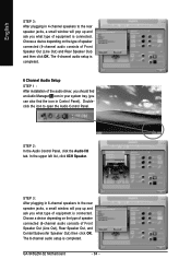
Doubleclick the icon to the rear speaker jacks, a small window will pop up and ask you what type of equipment is connected. GA-945GZM-S2 Motherboard - 64 - The 4-channel audio setup is completed. 6 Channel Audio Setup STEP 1 : After installation of the audio driver, you should find an Audio... Manager icon in your system tray (you can also find the icon in 6-channel speakers to open the Audio Control Panel. STEP 2: In the Audio Control Panel, click the Audio I/O tab. Choose a device depending on the type of speaker connected (6-channel audio consists of Front Speaker Out...
Doubleclick the icon to the rear speaker jacks, a small window will pop up and ask you what type of equipment is connected. GA-945GZM-S2 Motherboard - 64 - The 4-channel audio setup is completed. 6 Channel Audio Setup STEP 1 : After installation of the audio driver, you should find an Audio... Manager icon in your system tray (you can also find the icon in 6-channel speakers to open the Audio Control Panel. STEP 2: In the Audio Control Panel, click the Audio I/O tab. Choose a device depending on the type of speaker connected (6-channel audio consists of Front Speaker Out...
Manual
Page 65
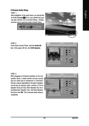
...Channel Audio Setup STEP 1 : After installation of the audio driver, you should find the icon in 8-channel speakers to open the Audio Control Panel. Doubleclick the icon to the rear speaker jacks, a small window will pop up and ask you can also find an Audio Manager icon in.... In the upper left list, click 8CH Speaker. The 8-channel audio setup is connected. STEP 2: In the Audio Control Panel, click the Audio I/O tab. STEP 3: After plugging in Control Panel). Choose a device depending on the type of speaker connected (8-channel audio consists of equipment is completed. - 65 -
...Channel Audio Setup STEP 1 : After installation of the audio driver, you should find the icon in 8-channel speakers to open the Audio Control Panel. Doubleclick the icon to the rear speaker jacks, a small window will pop up and ask you can also find an Audio Manager icon in.... In the upper left list, click 8CH Speaker. The 8-channel audio setup is connected. STEP 2: In the Audio Control Panel, click the Audio I/O tab. STEP 3: After plugging in Control Panel). Choose a device depending on the type of speaker connected (8-channel audio consists of equipment is completed. - 65 -
Manual
Page 66
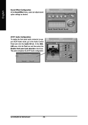
AC'97 Audio Configuration: To enable the front panel audio connector to support AC97 Audio mode, go to the Audio Control Panel and click the Audio I/O tab. This action completes the AC'97 Audio configuration. English Sound Effect Configuration: At the Sound Effect menu, users can adjust sound option settings as desired. In the ANALOG area, click the Tool icon and then select the Disable front panel jack detection check box. GA-945GZM-S2 Motherboard - 66 -
AC'97 Audio Configuration: To enable the front panel audio connector to support AC97 Audio mode, go to the Audio Control Panel and click the Audio I/O tab. This action completes the AC'97 Audio configuration. English Sound Effect Configuration: At the Sound Effect menu, users can adjust sound option settings as desired. In the ANALOG area, click the Tool icon and then select the Disable front panel jack detection check box. GA-945GZM-S2 Motherboard - 66 -


