
Manual
Page 4
... CPU 12 1-3-2 Installation of the CPU Cooler 13 1-4 Installation of Memory 14 1-5 Installation of Expansion Cards 15 1-6 I/O Back Panel Introduction 17 1-7 Connectors Introduction 18 Chapter 2 BIOS Setup 29 The Main Menu (For example: BIOS Ver. : FHa 30 2-1 Standard CMOS Features 32 2-2 Advanced BIOS Features 34 2-3 IntegratedPeripherals 36 2-4 Power Management Setup 40 2-5 PnP/PCI Configurations 42 2-6 PC Health Status 43 2-7 Frequency/Voltage Control 45 2-8 Load Fail-Safe Defaults 47 2-9 Load Optimized Defaults 47 2-10 Set Supervisor/User Password 48 2-11 Save & Exit Setup...
... CPU 12 1-3-2 Installation of the CPU Cooler 13 1-4 Installation of Memory 14 1-5 Installation of Expansion Cards 15 1-6 I/O Back Panel Introduction 17 1-7 Connectors Introduction 18 Chapter 2 BIOS Setup 29 The Main Menu (For example: BIOS Ver. : FHa 30 2-1 Standard CMOS Features 32 2-2 Advanced BIOS Features 34 2-3 IntegratedPeripherals 36 2-4 Power Management Setup 40 2-5 PnP/PCI Configurations 42 2-6 PC Health Status 43 2-7 Frequency/Voltage Control 45 2-8 Load Fail-Safe Defaults 47 2-9 Load Optimized Defaults 47 2-10 Set Supervisor/User Password 48 2-11 Save & Exit Setup...
Manual
Page 10
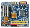
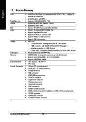
... x16 slot(Note 1) Š 3 PCI slots Internal Connectors Š 1 24-pin ATX power connector Š 1 4-pin ATX 12V power connector Š 1 floppy connector Š 1 IDE connector Š 4 SATA 3Gb/s connectors Š 1 CPU fan connector Š 1 system fan connector Š 1 front panel connector Š 1 front audio connector Š 1 CD In connector Š 1 S/PDIF In/Out connector Š 2 USB 2.0/1.1 connectors for additional 4 USB 2.0/1.1 ports by cables Š 1 COMB connector Š 1 power LED connector Š 1 Chassis Intrusion connector GA-945GZM-S2 Motherboard...
... x16 slot(Note 1) Š 3 PCI slots Internal Connectors Š 1 24-pin ATX power connector Š 1 4-pin ATX 12V power connector Š 1 floppy connector Š 1 IDE connector Š 4 SATA 3Gb/s connectors Š 1 CPU fan connector Š 1 system fan connector Š 1 front panel connector Š 1 front audio connector Š 1 CD In connector Š 1 S/PDIF In/Out connector Š 2 USB 2.0/1.1 connectors for additional 4 USB 2.0/1.1 ports by cables Š 1 COMB connector Š 1 power LED connector Š 1 Chassis Intrusion connector GA-945GZM-S2 Motherboard...
Manual
Page 11
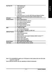
... port Š 1 parallel port Š 1 VGA port Š 1 serial port Š 4 USB 2.0/1.1 ports Š 1 RJ-45 port Š 6 audio jacks (Line In / Line Out / MIC In/Surround Speaker Out (Rear Speaker Out)/Center/Subwoofer Speaker Out/Side Speaker Out) I/O Control Š IT8718 chip Hardware Monitor Š System voltage detection Š CPU / System temperature detection Š CPU / System fan speed detection Š CPU warning temperature Š CPU / System fan failure warning Š CPU Smart Fan Control BIOS Š 1 4 Mbit flash ROM Š Use of licensed AWARD BIOS...
... port Š 1 parallel port Š 1 VGA port Š 1 serial port Š 4 USB 2.0/1.1 ports Š 1 RJ-45 port Š 6 audio jacks (Line In / Line Out / MIC In/Surround Speaker Out (Rear Speaker Out)/Center/Subwoofer Speaker Out/Side Speaker Out) I/O Control Š IT8718 chip Hardware Monitor Š System voltage detection Š CPU / System temperature detection Š CPU / System fan speed detection Š CPU warning temperature Š CPU / System fan failure warning Š CPU Smart Fan Control BIOS Š 1 4 Mbit flash ROM Š Use of licensed AWARD BIOS...
Manual
Page 13
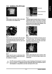
... the CPU fan header located on the motherboard.Pressing down the push pins diagonally. To prevent such an occurrence, it is complete. If the push pin is only for heat dissipation or using extreme care when removing the CPU cooler. - 13 - Fig. 4 Please make sure the Male and Female push pin are joined closely. (for detailed installation instructions, please refer to the CPU cooler installation...
... the CPU fan header located on the motherboard.Pressing down the push pins diagonally. To prevent such an occurrence, it is complete. If the push pin is only for heat dissipation or using extreme care when removing the CPU cooler. - 13 - Fig. 4 Please make sure the Male and Female push pin are joined closely. (for detailed installation instructions, please refer to the CPU cooler installation...

Manual
Page 15
.... If you must install them into the PCI Express x16 slot. Press the expansion card firmly into the computer. 2. For example: Installing a PCI Express x16 VGA card: When installing the graphics card, push down on the card are indeed seated in the slot and does not rock. To enable Dual Channel mode with two memory modules (it is securely seated in the slot. 5. Install related driver from BIOS. 8. Hardware Installation English Dual Channel Memory Configuration The GA-945GZM-S2 supports the Dual Channel Technology. Be sure...
.... If you must install them into the PCI Express x16 slot. Press the expansion card firmly into the computer. 2. For example: Installing a PCI Express x16 VGA card: When installing the graphics card, push down on the card are indeed seated in the slot and does not rock. To enable Dual Channel mode with two memory modules (it is securely seated in the slot. 5. Install related driver from BIOS. 8. Hardware Installation English Dual Channel Memory Configuration The GA-945GZM-S2 supports the Dual Channel Technology. Be sure...

Manual
Page 16
... GV-RX80256D GV-RX30HM128D GV-RX55128D GV-RX85T256V-B GV-RC850T256D-B GV-RX13P256D-RH GV-RX16P256D-RH GV-RX18L256V-B GV-RX18T512V-B AX800XT AX700PRO RX600 XT-TD128 GA-945GZM-S2 Motherboard - 16 - When using an add-on graphics card, please first delete the onboard graphics driver before installing the driver for the add-on...
... GV-RX80256D GV-RX30HM128D GV-RX55128D GV-RX85T256V-B GV-RC850T256D-B GV-RX13P256D-RH GV-RX16P256D-RH GV-RX18L256V-B GV-RX18T512V-B AX800XT AX700PRO RX600 XT-TD128 GA-945GZM-S2 Motherboard - 16 - When using an add-on graphics card, please first delete the onboard graphics driver before installing the driver for the add-on...
Manual
Page 18
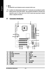
... default speakers settings, the ~ audio jacks can be connected to perform different functions via the audio software. channel audio setup steps for detailed software configuration information. 1-7 Connectors Introduction 1 3 4 10 11 12 14 1) ATX_12V 2) ATX (Power Connector) 3) CPU_FAN 4) SYS_FAN 5) IDE 6) FDD 7) SATAII 0 / 1 / 2 / 3 8) PWR_LED 9) F_PANEL 2 5 6 7 17 15 9 13 8 16 10) F_AUDIO 11) CD_IN 12) SPDIF_IO 13) F_USB1 / F_USB2 14) COMB 15) CI 16) CLR_CMOS 17) BATTERY GA-945GZM-S2 Motherboard - 18 - Microphone must be connected...
... default speakers settings, the ~ audio jacks can be connected to perform different functions via the audio software. channel audio setup steps for detailed software configuration information. 1-7 Connectors Introduction 1 3 4 10 11 12 14 1) ATX_12V 2) ATX (Power Connector) 3) CPU_FAN 4) SYS_FAN 5) IDE 6) FDD 7) SATAII 0 / 1 / 2 / 3 8) PWR_LED 9) F_PANEL 2 5 6 7 17 15 9 13 8 16 10) F_AUDIO 11) CD_IN 12) SPDIF_IO 13) F_USB1 / F_USB2 14) COMB 15) CI 16) CLR_CMOS 17) BATTERY GA-945GZM-S2 Motherboard - 18 - Microphone must be connected...

Manual
Page 20
... IDE connector. 40 39 GA-945GZM-S2 Motherboard - 20 - 2 1 Remember to connect the CPU/system fan cable to the CPU_FAN/SYS_FAN connector to prevent CPU damage or system hanging caused by overheating. 1 CPU_FAN 1 SYS_FAN CPU_FAN: Pin No. 1 2 3 4 Definition GND +12V/Speed Control Sense Speed Control SYS_FAN: Pin No. 1 2 3 Definition GND +12V Sense 5) IDE (IDE Connector) An IDE device connects to two IDE devices (hard drive or optical drive). English 3/4) CPU_FAN / SYS_FAN (Cooler Fan Power Connector) The cooler fan power connector supplies a +12V power voltage via an IDE connector...
... IDE connector. 40 39 GA-945GZM-S2 Motherboard - 20 - 2 1 Remember to connect the CPU/system fan cable to the CPU_FAN/SYS_FAN connector to prevent CPU damage or system hanging caused by overheating. 1 CPU_FAN 1 SYS_FAN CPU_FAN: Pin No. 1 2 3 4 Definition GND +12V/Speed Control Sense Speed Control SYS_FAN: Pin No. 1 2 3 Definition GND +12V Sense 5) IDE (IDE Connector) An IDE device connects to two IDE devices (hard drive or optical drive). English 3/4) CPU_FAN / SYS_FAN (Cooler Fan Power Connector) The cooler fan power connector supplies a +12V power voltage via an IDE connector...

Manual
Page 21
... the BIOS setting for the SATA 3Gb/s and install the proper driver in the FDD connector. 34 33 2 1 7) SATAII 0 / 1 / 2 / 3 (SATA 3Gb/s Connector) SATA 3Gb/s can provide up to 300 MB/s transfer rate. The types of the foolproof groove in order to the FDD drive. English 6) FDD (FDD Connector) The FDD connector is used to connect the FDD cable while the other end of the cable connects to work properly...
... the BIOS setting for the SATA 3Gb/s and install the proper driver in the FDD connector. 34 33 2 1 7) SATAII 0 / 1 / 2 / 3 (SATA 3Gb/s Connector) SATA 3Gb/s can provide up to 300 MB/s transfer rate. The types of the foolproof groove in order to the FDD drive. English 6) FDD (FDD Connector) The FDD connector is used to connect the FDD cable while the other end of the cable connects to work properly...
Manual
Page 22
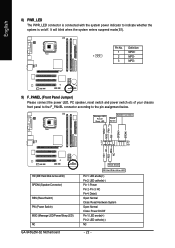
... Disk Active LED) SPEAK (Speaker Connector) RES (Reset Switch) PW (Power Switch) MSG (Message LED/Power/Sleep LED) NC GA-945GZM-S2 Motherboard Reset Switch IDE Hard Disk Active LED Pin 1: LED anode(+) Pin 2: LED cathode(-) Pin 1: Power Pin 2- Definition 1 MPD+ 1 2 MPD- 3 MPD- 9) F_PANEL (Front Panel Jumper) Please connect the power LED, PC speaker, reset switch and power switch etc of your chassis front panel to the F_PANEL connector according to indicate whether the system is on/off. PW+ PWSPEAK+ SPEAK- 2 20 1 19 HD+ HD- It will blink when the system enters suspend mode...
... Disk Active LED) SPEAK (Speaker Connector) RES (Reset Switch) PW (Power Switch) MSG (Message LED/Power/Sleep LED) NC GA-945GZM-S2 Motherboard Reset Switch IDE Hard Disk Active LED Pin 1: LED anode(+) Pin 2: LED cathode(-) Pin 1: Power Pin 2- Definition 1 MPD+ 1 2 MPD- 3 MPD- 9) F_PANEL (Front Panel Jumper) Please connect the power LED, PC speaker, reset switch and power switch etc of your chassis front panel to the F_PANEL connector according to indicate whether the system is on/off. PW+ PWSPEAK+ SPEAK- 2 20 1 19 HD+ HD- It will blink when the system enters suspend mode...
Manual
Page 30
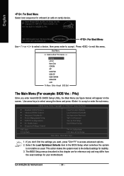
...BIOS Features ` Integrated Peripherals ` Power Management Setup ` PnP/PCI Configurations ` PC Health Status ` Frequency/Voltage Control ESC: Quit F8: Q-Flash Load Fail-Safe Defaults Load Optimized Defaults Set Supervisor Password Set User Password Save & Exit Setup Exit Without Saving KLJI: Select Item F10: Save & Exit Setup Time, Date, Hard Disk Type... 1. Intel I945 BIOS for stability. 3. If you don't find the settings you enter Award BIOS CMOS Setup Utility, the Main Menu (as usual. English : For Boot Menu Select boot sequence for onboard (or add-on the screen. Use arrow keys...
...BIOS Features ` Integrated Peripherals ` Power Management Setup ` PnP/PCI Configurations ` PC Health Status ` Frequency/Voltage Control ESC: Quit F8: Q-Flash Load Fail-Safe Defaults Load Optimized Defaults Set Supervisor Password Set User Password Save & Exit Setup Exit Without Saving KLJI: Select Item F10: Save & Exit Setup Time, Date, Hard Disk Type... 1. Intel I945 BIOS for stability. 3. If you don't find the settings you enter Award BIOS CMOS Setup Utility, the Main Menu (as usual. English : For Boot Menu Select boot sequence for onboard (or add-on the screen. Use arrow keys...

Manual
Page 32
... in . IDE Channel 0 Master/Slave IDE/SATA Device Setup. GA-945GZM-S2 Motherboard - 32 - English 2-1 Standard CMOS Features Date (mm:dd:yy) Time (hh:mm:ss) CMOS Setup Utility-Copyright (C) 1984-2007 Award Software Standard CMOS Features Fri, Apr 20 2007 14:31:24 Item Help Menu Level` ` IDE Channel 0 Master ` IDE Channel 0 Slave ` IDE Channel 2 Master ` IDE Channel 2 Slave ` IDE Channel 3 Master ` IDE Channel 3 Slave [None] [None] [None] [None] [None] [None] Drive A Floppy 3 Mode Support [1.44M, 3.5"] [Disabled] Halt On [All, But Keyboard] Base Memory Extended Memory 640K...
... in . IDE Channel 0 Master/Slave IDE/SATA Device Setup. GA-945GZM-S2 Motherboard - 32 - English 2-1 Standard CMOS Features Date (mm:dd:yy) Time (hh:mm:ss) CMOS Setup Utility-Copyright (C) 1984-2007 Award Software Standard CMOS Features Fri, Apr 20 2007 14:31:24 Item Help Menu Level` ` IDE Channel 0 Master ` IDE Channel 0 Slave ` IDE Channel 2 Master ` IDE Channel 2 Slave ` IDE Channel 3 Master ` IDE Channel 3 Slave [None] [None] [None] [None] [None] [None] Drive A Floppy 3 Mode Support [1.44M, 3.5"] [Disabled] Halt On [All, But Keyboard] Base Memory Extended Memory 640K...
Manual
Page 37
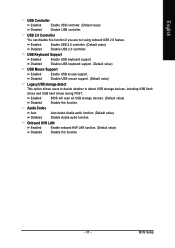
Disabled Disable USB keyboard support. (Default value) USB Mouse Support Enabled Enable USB mouse support. Disabled Disable USB mouse support. (Default value) Legacy USB storage detect This option allows users to decide whether to detect USB storage devices, including USB flash drives and USB hard drives during POST. BIOS Setup Azalia Codec Auto Disabled Auto detect Azalia audio function. (Default value) Disable Azalia audio function. Enabled Disabled Enable USB 2.0 controller. (Default value) Disable USB 2.0 controller. Enabled BIOS will scan all USB storage ...
Disabled Disable USB keyboard support. (Default value) USB Mouse Support Enabled Enable USB mouse support. Disabled Disable USB mouse support. (Default value) Legacy USB storage detect This option allows users to decide whether to detect USB storage devices, including USB flash drives and USB hard drives during POST. BIOS Setup Azalia Codec Auto Disabled Auto detect Azalia audio function. (Default value) Disable Azalia audio function. Enabled Disabled Enable USB 2.0 controller. (Default value) Disable USB 2.0 controller. Enabled BIOS will scan all USB storage ...
Manual
Page 45
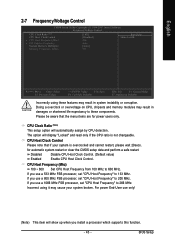
... MHz FSB processor, set "CPU Host Frequency" to 200 MHz. For power End-User use a 1066 MHz FSB processor, set "CPU Host Frequency" to 600 MHz. English 2-7 Frequency/Voltage Control CMOS Setup Utility-Copyright (C) 1984-2007 Award Software Frequency/Voltage Control CPU Clock Ratio (Note) CPU Host Clock Control x CPU Host Frequency(Mhz) x PCI Express Frequency System Memory Multiplier Memory Frequency (Mhz) [18X] [Disabled] 200 Auto [Auto] 533 Item Help Menu Level` KLJI: Move Enter: Select F5: Previous Values +/-/PU/PD: Value F10: Save F6: Fail-Safe Defaults ESC...
... MHz FSB processor, set "CPU Host Frequency" to 200 MHz. For power End-User use a 1066 MHz FSB processor, set "CPU Host Frequency" to 600 MHz. English 2-7 Frequency/Voltage Control CMOS Setup Utility-Copyright (C) 1984-2007 Award Software Frequency/Voltage Control CPU Clock Ratio (Note) CPU Host Clock Control x CPU Host Frequency(Mhz) x PCI Express Frequency System Memory Multiplier Memory Frequency (Mhz) [18X] [Disabled] 200 Auto [Auto] 533 Item Help Menu Level` KLJI: Move Enter: Select F5: Previous Values +/-/PU/PD: Value F10: Save F6: Fail-Safe Defaults ESC...

Manual
Page 48
... select "Setup" at "Password Check" in creating a password. GA-945GZM-S2 Motherboard - 48 - Type the password again and press . A message "PASSWORD DISABLED" will boot and you can enter Setup freely. English 2-10 Set Supervisor/User Password CMOS Setup Utility-Copyright (C) 1984-2007 Award Software ` Standard CMOS Features ` Advanced BIOS Features ` Integrated Peripherals ` Power Management Setup ` PnP/PCI ConfiguratioEnsnter Password: ` PC Health Status ` Frequency/Voltage Control Load Fail-Safe Defaults Load Optimized Defaults Set Supervisor Password Set User Password Save...
... select "Setup" at "Password Check" in creating a password. GA-945GZM-S2 Motherboard - 48 - Type the password again and press . A message "PASSWORD DISABLED" will boot and you can enter Setup freely. English 2-10 Set Supervisor/User Password CMOS Setup Utility-Copyright (C) 1984-2007 Award Software ` Standard CMOS Features ` Advanced BIOS Features ` Integrated Peripherals ` Power Management Setup ` PnP/PCI ConfiguratioEnsnter Password: ` PC Health Status ` Frequency/Voltage Control Load Fail-Safe Defaults Load Optimized Defaults Set Supervisor Password Set User Password Save...
Manual
Page 51
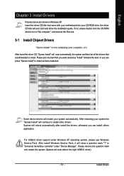
... will auto start and show a question mark "?" in Windows XP. Install Drivers For USB2.0 driver support under "Device Manager". English Chapter 3 Install Drivers Pictures below are shown in "Universal Serial Bus controller" under Windows XP operating system, please use Windows Service Pack. Insert the driver CD-title that came with your motherboard into your CD-ROM drive, the driver CD-title will reboot automatically after install the drivers, afterward you can install others application. After install Windows Service...
... will auto start and show a question mark "?" in Windows XP. Install Drivers For USB2.0 driver support under "Device Manager". English Chapter 3 Install Drivers Pictures below are shown in "Universal Serial Bus controller" under Windows XP operating system, please use Windows Service Pack. Insert the driver CD-title that came with your motherboard into your CD-ROM drive, the driver CD-title will reboot automatically after install the drivers, afterward you can install others application. After install Windows Service...

Manual
Page 56
... in the bottom left corner of system memory 3. VESA-supported VGA cards How to use the Xpress Recovery2 Initial access by booting from CD/DVD: Press any key to enter Xpress Recovery2. English 4-1-2 Xpress Recovery2 Introduction Xpress Recovery2 is able to back up data on hard disks on . . . System storage capacity and the reading/writing speed of the hard disk will appear in your CD-ROM drive. GA-945GZM-S2 Motherboard - 56 -
... in the bottom left corner of system memory 3. VESA-supported VGA cards How to use the Xpress Recovery2 Initial access by booting from CD/DVD: Press any key to enter Xpress Recovery2. English 4-1-2 Xpress Recovery2 Introduction Xpress Recovery2 is able to back up data on hard disks on . . . System storage capacity and the reading/writing speed of the hard disk will appear in your CD-ROM drive. GA-945GZM-S2 Motherboard - 56 -

Manual
Page 58
... the independent IDE/SATA controller. Award Modular BIOS v6.00PG, An Energy Star Ally Copyright (C) 1984-2007, Award Software, Inc. b. Select the floppy drive or hard drive where the BIOS file is saved, such as "Floppy A" and press ENTER. Updating the BIOS Step 1: a. During BIOS POST, press the End key to select Update BIOS from Drive Sa0vefilBeI(Os)SfotounDdrive EnteFr l:oRppuyn A :Move ESC:Reset :Power Off HDD 0-0 Total size : 0 F5 : Refresh GA-945GZM-S2 Motherboard Free size : 0 DEL : Delete - 58 - English 4-1-3 Flash BIOS Method Introduction...
... the independent IDE/SATA controller. Award Modular BIOS v6.00PG, An Energy Star Ally Copyright (C) 1984-2007, Award Software, Inc. b. Select the floppy drive or hard drive where the BIOS file is saved, such as "Floppy A" and press ENTER. Updating the BIOS Step 1: a. During BIOS POST, press the End key to select Update BIOS from Drive Sa0vefilBeI(Os)SfotounDdrive EnteFr l:oRppuyn A :Move ESC:Reset :Power Off HDD 0-0 Total size : 0 F5 : Refresh GA-945GZM-S2 Motherboard Free size : 0 DEL : Delete - 58 - English 4-1-3 Flash BIOS Method Introduction...
Manual
Page 60
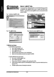
... download the latest version of BIOS. Please search for BIOS unzip file, downloading from internet or any other methods (such as: 9gzms21.F1). Installing the @BIOS utility Fig 2. Installation Complete and Run @BIOS Select @BIOS item than click Install Fig 3. Click "Internet Update" icon b. Just select the desired @BIOS server to update their BIOS under Windows. Select the desired @BIOS server 1. Click "Update New BIOS" icon c. System will automatically download and update the BIOS. d. e. GA-945GZM-S2 Motherboard...
... download the latest version of BIOS. Please search for BIOS unzip file, downloading from internet or any other methods (such as: 9gzms21.F1). Installing the @BIOS utility Fig 2. Installation Complete and Run @BIOS Select @BIOS item than click Install Fig 3. Click "Internet Update" icon b. Just select the desired @BIOS server to update their BIOS under Windows. Select the desired @BIOS server 1. Click "Update New BIOS" icon c. System will automatically download and update the BIOS. d. e. GA-945GZM-S2 Motherboard...

Manual
Page 67
...: CMOS setting error 1 long 1 short: DRAM or M/B error 1 long 2 short: Monitor or display card error 1 long 3 short: Keyboard error 1 long 9 short: BIOS ROM error Continuous long beeps: DRAM error Continuous short beeps: Power error - 67 - Answer: In some options that 's why the light is still on power. 6. Disconnect the power cord from case to case. If not, please change another speaker with an internal amplifier. Why? Questions 2: Why is the light of my keyboard/optical mouse still on -board battery to leak voltage to clear CMOS. Connect power cord to MB again and turn...
...: CMOS setting error 1 long 1 short: DRAM or M/B error 1 long 2 short: Monitor or display card error 1 long 3 short: Keyboard error 1 long 9 short: BIOS ROM error Continuous long beeps: DRAM error Continuous short beeps: Power error - 67 - Answer: In some options that 's why the light is still on power. 6. Disconnect the power cord from case to case. If not, please change another speaker with an internal amplifier. Why? Questions 2: Why is the light of my keyboard/optical mouse still on -board battery to leak voltage to clear CMOS. Connect power cord to MB again and turn...


