User Manual
Page 2
... of Content Item Checklist 4 GA-8IPXDR-E Series Model List 4 WARNING 4 Chapter 1 Introduction 6 Features Summary 6 GA-8IPXDR-E(C) Motherboard Layout 8 Chapter 2 Hardware Installation Process 9 Step 1: Install the Central Processing Unit (CPU 10 Step 1-1: Installing Motherboard to the Chassis 10 Step 1-2: CPU Installation 11 ...
... of Content Item Checklist 4 GA-8IPXDR-E Series Model List 4 WARNING 4 Chapter 1 Introduction 6 Features Summary 6 GA-8IPXDR-E(C) Motherboard Layout 8 Chapter 2 Hardware Installation Process 9 Step 1: Install the Central Processing Unit (CPU 10 Step 1-1: Installing Motherboard to the Chassis 10 Step 1-2: CPU Installation 11 ...
User Manual
Page 3
Table of Content Chapter 4 Technical Reference 60 GA-8IPXDR-E System Block Diagram 60 Chapter 5 Appendix 61 Appendix A: Intel Network Driver Installation 61 Appendix B: INF Update Installation (Driver for chipset 63 Appendix C: ATI Rage XL VGA Driver Installation 64 Appexdix D: Adaptec SCSI Driver Installation 65 Appendix E: Utilites Installation 66 Appendix F: About Updateing Latest version of BIOS 66 Appendix G: IPMI Connector Pin Definition 67 Appendix H: Acronyms 68 Technical Support/RMA Sheet 70 3
Table of Content Chapter 4 Technical Reference 60 GA-8IPXDR-E System Block Diagram 60 Chapter 5 Appendix 61 Appendix A: Intel Network Driver Installation 61 Appendix B: INF Update Installation (Driver for chipset 63 Appendix C: ATI Rage XL VGA Driver Installation 64 Appexdix D: Adaptec SCSI Driver Installation 65 Appendix E: Utilites Installation 66 Appendix F: About Updateing Latest version of BIOS 66 Appendix G: IPMI Connector Pin Definition 67 Appendix H: Acronyms 68 Technical Support/RMA Sheet 70 3
User Manual
Page 4
... cable x 1 ; Use a grounded wrist strap before you work on the motherboard. 4 Ensure that came with SCSI function) 3 GA-8IPXDR-EC (Supports 533MHz / without SCSI function) WARNING! The GA-8IPXDR-E series motherboard ; Driver CD for motherboard driver & utility ; To protect them against damage from the system. 5. If you do ... when working on the bag that the ATX power supply is switched off before handling computer components. GA-8IPXDR-E(C) Motherboard Item Checklist ; SCSI Cable x 1 (Optional) ; Place components on a grounded antistatic pad or on the inside. 2.
... cable x 1 ; Use a grounded wrist strap before you work on the motherboard. 4 Ensure that came with SCSI function) 3 GA-8IPXDR-EC (Supports 533MHz / without SCSI function) WARNING! The GA-8IPXDR-E series motherboard ; Driver CD for motherboard driver & utility ; To protect them against damage from the system. 5. If you do ... when working on the bag that the ATX power supply is switched off before handling computer components. GA-8IPXDR-E(C) Motherboard Item Checklist ; SCSI Cable x 1 (Optional) ; Place components on a grounded antistatic pad or on the inside. 2.
User Manual
Page 6
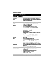
... 604 socket for up to 4 ATAPI devices y Supports up to ATA100 IDE & ATAPI CD-ROM y 1 Floppy port supports 360K, 720K,1.2M, 1.44M and 2.88M bytes. GA-8IPXDR-E(C) Motherboard Chapter 1 Introduction Features Summary Form Factor CPU y 30.5cm x 33cm Extend ATX size form factor, 8 layers PCB.
... 604 socket for up to 4 ATAPI devices y Supports up to ATA100 IDE & ATAPI CD-ROM y 1 Floppy port supports 360K, 720K,1.2M, 1.44M and 2.88M bytes. GA-8IPXDR-E(C) Motherboard Chapter 1 Introduction Features Summary Form Factor CPU y 30.5cm x 33cm Extend ATX size form factor, 8 layers PCB.
User Manual
Page 8
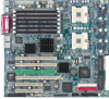
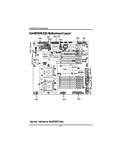
GA-8IPXDR-E(C) Motherboard GA-8IPXDR-E(C) Motherboard Layout FDD1 USB1 IPMI_CON IDE1 BIOS COM2 J20 *SCSI1 (Channel *SCSI2 (Channel B) A) ICH3-S IDE2 *SCSI 7902W CLR_COMS BT1 P64H2 SIO NS Wake on LAN PCI_6 PCI_5 PCI_4 ATI Rage XL PCI-X_3 PCI-X_2 PCI-X_1 CPU2 E7501 P64H2 82546EB J4 (B-1) J1 (A-1) J5 (B-2) J2 (A-2) J6 (B-3) J3 (A-3) 604 PIN Socket 604 PIN Socket CPU1 (Install First) ATX2 ATX1 ATX3 CN1 USB2 COM1LPT VGA LAN1 LAN2 Note that * indicates for GA-8IPXDR-E Only 8
GA-8IPXDR-E(C) Motherboard GA-8IPXDR-E(C) Motherboard Layout FDD1 USB1 IPMI_CON IDE1 BIOS COM2 J20 *SCSI1 (Channel *SCSI2 (Channel B) A) ICH3-S IDE2 *SCSI 7902W CLR_COMS BT1 P64H2 SIO NS Wake on LAN PCI_6 PCI_5 PCI_4 ATI Rage XL PCI-X_3 PCI-X_2 PCI-X_1 CPU2 E7501 P64H2 82546EB J4 (B-1) J1 (A-1) J5 (B-2) J2 (A-2) J6 (B-3) J3 (A-3) 604 PIN Socket 604 PIN Socket CPU1 (Install First) ATX2 ATX1 ATX3 CN1 USB2 COM1LPT VGA LAN1 LAN2 Note that * indicates for GA-8IPXDR-E Only 8
User Manual
Page 10
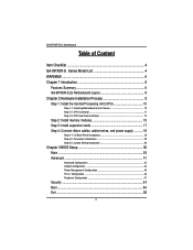
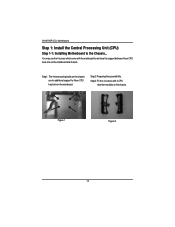
Step2: Preparing the assemblt kits. Step3: Fit the 4 screws with the mainboard to the Chassis... You may use the 4 screws which come with 2 CPU retention modules on the chassis. Step1: The 4 new mounting holes on the chassis are for additional support for Xeon CPU heat-sink on the mainboard. Figure 1 Figure 2 10 GA-8IPXDR-E(C) Motherboard Step 1: Install the Central Processing Unit (CPU) Step 1-1: Installing Motherboard to reinforce the support between Xeon CPU heat-sink on the mainboard and chassis.
Step2: Preparing the assemblt kits. Step3: Fit the 4 screws with the mainboard to the Chassis... You may use the 4 screws which come with 2 CPU retention modules on the chassis. Step1: The 4 new mounting holes on the chassis are for additional support for Xeon CPU heat-sink on the mainboard. Figure 1 Figure 2 10 GA-8IPXDR-E(C) Motherboard Step 1: Install the Central Processing Unit (CPU) Step 1-1: Installing Motherboard to reinforce the support between Xeon CPU heat-sink on the mainboard and chassis.
User Manual
Page 12
... 1 in the socket and look for a (golden) cut edge well, it will cause improper installation. Press down the CPU socket lever and finish CPU installation. GA-8IPXDR-E(C) Motherboard 3.
... 1 in the socket and look for a (golden) cut edge well, it will cause improper installation. Press down the CPU socket lever and finish CPU installation. GA-8IPXDR-E(C) Motherboard 3.
User Manual
Page 14
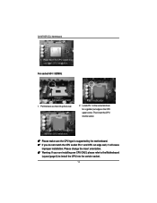
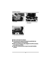
Picture of the cooler bracket to CPU heat sink user's manual for more detail installation procedure. 14 GA-8IPXDR-E(C) Motherboard 7. Hook one end of device set on the motherboard. 0 Please use Intel approved cooling fan. 0 We recommend you to apply the thermal paste to provide better heat conduction between your CPU and heatsink. 0 Make sure the CPU fan power cable is plugged in to the CPU fan connector, this completes the installation. 0 Please refer to the CPU socket first. 9. Fan assembly. 8.
Picture of the cooler bracket to CPU heat sink user's manual for more detail installation procedure. 14 GA-8IPXDR-E(C) Motherboard 7. Hook one end of device set on the motherboard. 0 Please use Intel approved cooling fan. 0 We recommend you to apply the thermal paste to provide better heat conduction between your CPU and heatsink. 0 Make sure the CPU fan power cable is plugged in to the CPU fan connector, this completes the installation. 0 Please refer to the CPU socket first. 9. Fan assembly. 8.
User Manual
Page 16
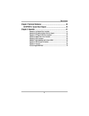
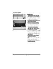
... installing the memoryin the DIMM module, please insert them pair by pair. Reverse the installation steps when you want to remove the DIMM module. 16 GA-8IPXDR-E(C) Motherboard J4 (B-1) J1 (A-1) J5 (B-2) J2 (A-2) J6 (B-3) J3 (A-3) Installation Step: 1. The DIMM slot has a notch, so the DIMM memory module can only fit in J3/J6...
... installing the memoryin the DIMM module, please insert them pair by pair. Reverse the installation steps when you want to remove the DIMM module. 16 GA-8IPXDR-E(C) Motherboard J4 (B-1) J1 (A-1) J5 (B-2) J2 (A-2) J6 (B-3) J3 (A-3) Installation Step: 1. The DIMM slot has a notch, so the DIMM memory module can only fit in J3/J6...
User Manual
Page 18
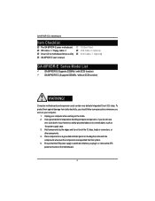
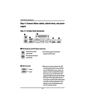
... USB 0 USB 1 ¾Before you connect your device(s) into USB connector(s), please make sure your device(s) such as USB keyboard, mouse, scanner, zip, speaker..etc. GA-8IPXDR-E(C) Motherboard Step 4: Connect ribbon cables, cabinet wires, and power supply Step 4-1: I/O Back Panel Introduction X Z Y [ \ X PS/2 Keyboard and PS/2 Mouse Connector PS/2 Mouse Connector (6 pin Female...
... USB 0 USB 1 ¾Before you connect your device(s) into USB connector(s), please make sure your device(s) such as USB keyboard, mouse, scanner, zip, speaker..etc. GA-8IPXDR-E(C) Motherboard Step 4: Connect ribbon cables, cabinet wires, and power supply Step 4-1: I/O Back Panel Introduction X Z Y [ \ X PS/2 Keyboard and PS/2 Mouse Connector PS/2 Mouse Connector (6 pin Female...
User Manual
Page 20
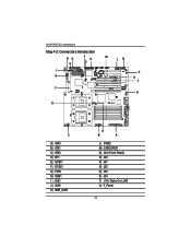
GA-8IPXDR-E(C) Motherboard Step 4-2: Connectors Introduction HG S J K D I E F Q M LN P U T R C A) ATX3 B) ATX1 C) ATX2 D) BT1 E) SCSI1 F) SCSI2 G) FDD1 H) USB1 I ) IDE1 J ) IDE2 K) IPMI_CON O B A L) COM2 M) CASEOPEN N) J20 (Front Panel) O) J30 P) J31 Q) J32 R) J33 S) J34 T) J18 ( Wake On LAN) U) F_Panel 20
GA-8IPXDR-E(C) Motherboard Step 4-2: Connectors Introduction HG S J K D I E F Q M LN P U T R C A) ATX3 B) ATX1 C) ATX2 D) BT1 E) SCSI1 F) SCSI2 G) FDD1 H) USB1 I ) IDE1 J ) IDE2 K) IPMI_CON O B A L) COM2 M) CASEOPEN N) J20 (Front Panel) O) J30 P) J31 Q) J32 R) J33 S) J34 T) J18 ( Wake On LAN) U) F_Panel 20
User Manual
Page 22
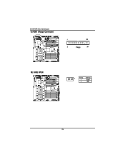
O/Q ) J30/J32 (CPU FAN Connector) J32 J30 1 1 J32:CPU1 FAN J30:CPU 0 FAN Pin No. 1 2 3 Definition GND +12v/Control Sense ¾Please note, a proper installation of the CPU cooler is used only for CPU Core Voltage. current up to prevent the CPU from running under abnormal condition or damaged by overheating.The CPU fan connector supports Max. GA-8IPXDR-E(C) Motherboard C) ATX2 (+12V Power Connector) 43 21 Pin No. 1 2 3 4 Definition GND GND +12V +12V ¾This connector (ATX +12V) is essential to 600mA . 22
O/Q ) J30/J32 (CPU FAN Connector) J32 J30 1 1 J32:CPU1 FAN J30:CPU 0 FAN Pin No. 1 2 3 Definition GND +12v/Control Sense ¾Please note, a proper installation of the CPU cooler is used only for CPU Core Voltage. current up to prevent the CPU from running under abnormal condition or damaged by overheating.The CPU fan connector supports Max. GA-8IPXDR-E(C) Motherboard C) ATX2 (+12V Power Connector) 43 21 Pin No. 1 2 3 4 Definition GND GND +12V +12V ¾This connector (ATX +12V) is essential to 600mA . 22
User Manual
Page 24
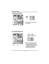
NC 24 GA-8IPXDR-E(C) Motherboard T) J18 (Wake On LAN Connector) 1 Pin No. 1 2 3 Definition +5VSB GND Signal L) COM 2 Connector 1 Pin No. 1 2 3 4 5 6 7 8 9 10 Definition NDCDB NSINB NSOUTB NDTRB GND NDSRBNRTSBNCTSBNRIB-
NC 24 GA-8IPXDR-E(C) Motherboard T) J18 (Wake On LAN Connector) 1 Pin No. 1 2 3 Definition +5VSB GND Signal L) COM 2 Connector 1 Pin No. 1 2 3 4 5 6 7 8 9 10 Definition NDCDB NSINB NSOUTB NDTRB GND NDSRBNRTSBNCTSBNRIB-
User Manual
Page 26
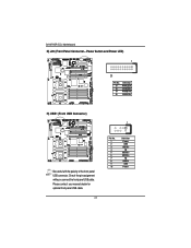
GA-8IPXDR-E(C) Motherboard G) FDD1 (Floppy Connector) 1 33 2 Floppy 34 M) CASE OPEN 1 Pin No. Definition 1 Signal 2 GND 26
GA-8IPXDR-E(C) Motherboard G) FDD1 (Floppy Connector) 1 33 2 Floppy 34 M) CASE OPEN 1 Pin No. Definition 1 Signal 2 GND 26
User Manual
Page 27
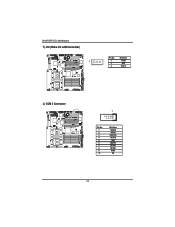
GA-8IPXDR-E(C) Motherboard N) J20 (Front Panel Connector-- Check the pin assignment while you connect the front panel USB cable. Power button and Power LED) 1 20 Pin No. 17 18 19 20 Definition PWR LED+ PWR LEDPWR BTN+ PWR BTN- Please contact your nearest dealer for optional front panel USB cable. 27 Pin No. 1 2 3 4 5 6 7 8 9 10 Definition Power GND USB D2NC USB D2+ USB D3+ NC USBD3GND Power H) USB1 (Front USB Connector) 1 Be careful with the polarity of the front panel USB connector.
GA-8IPXDR-E(C) Motherboard N) J20 (Front Panel Connector-- Check the pin assignment while you connect the front panel USB cable. Power button and Power LED) 1 20 Pin No. 17 18 19 20 Definition PWR LED+ PWR LEDPWR BTN+ PWR BTN- Please contact your nearest dealer for optional front panel USB cable. 27 Pin No. 1 2 3 4 5 6 7 8 9 10 Definition Power GND USB D2NC USB D2+ USB D3+ NC USBD3GND Power H) USB1 (Front USB Connector) 1 Be careful with the polarity of the front panel USB connector.
User Manual
Page 28
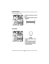
GA-8IPXDR-E(C) Motherboard K) IPMI_CON (IPMI Connector) ¾IPMI module is an optional device for customer to purchase. ¾For the IPMI connector pins definition, please refer to Appendix G. 2 70 1 69 D) BT1 (Battery) + CAUTION ™ Danger of explosion if battery is incorrectly replaced. ™ Replace only with the same or equivalent type recommended by the manufacturer. ™ Dispose of used batteries according to the manufacturer's instructions. 28
GA-8IPXDR-E(C) Motherboard K) IPMI_CON (IPMI Connector) ¾IPMI module is an optional device for customer to purchase. ¾For the IPMI connector pins definition, please refer to Appendix G. 2 70 1 69 D) BT1 (Battery) + CAUTION ™ Danger of explosion if battery is incorrectly replaced. ™ Replace only with the same or equivalent type recommended by the manufacturer. ™ Dispose of used batteries according to the manufacturer's instructions. 28
User Manual
Page 30
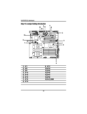
GA-8IPXDR-E(C) Motherboard Step 4-3: Jumper Setting Introduction 15 3 11 5 12 10 2 13 9 14 6 1 7 8 1) JP 1 2) JP 8 3) JP 9 4) JP 10 5) JP 13 6) JP 14 7) JP 15 8) JP 16 4 9) JP 17 10) JP 18 11) JP 19 12) JP 20 13) JP 21 14) JP 22 15) CLR_COMS 30
GA-8IPXDR-E(C) Motherboard Step 4-3: Jumper Setting Introduction 15 3 11 5 12 10 2 13 9 14 6 1 7 8 1) JP 1 2) JP 8 3) JP 9 4) JP 10 5) JP 13 6) JP 14 7) JP 15 8) JP 16 4 9) JP 17 10) JP 18 11) JP 19 12) JP 20 13) JP 21 14) JP 22 15) CLR_COMS 30
User Manual
Page 32
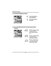
... ==>The Primary PCI-X max Bus frequency will stay at 100MHz 1 JP13 JP14 JP13 : JP14 = 2-3 closed ==>Set the Primary PCI-X max Bus frequency at 66MHz 32 GA-8IPXDR-E(C) Motherboard 4) JP 10 (Rear Side USB Wake Up Function) 1 1-2 close: Rear USB wake up function disabled (Default) 1 2-3 close: Rear USB wake up function enabled 5 / 6) JP13...
... ==>The Primary PCI-X max Bus frequency will stay at 100MHz 1 JP13 JP14 JP13 : JP14 = 2-3 closed ==>Set the Primary PCI-X max Bus frequency at 66MHz 32 GA-8IPXDR-E(C) Motherboard 4) JP 10 (Rear Side USB Wake Up Function) 1 1-2 close: Rear USB wake up function disabled (Default) 1 2-3 close: Rear USB wake up function enabled 5 / 6) JP13...
User Manual
Page 34
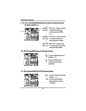
Open JP19 ==>The Secondary PCI-X max Bus frequency will stay at 100MHz JP20 : JP19 = 2-3 closed : SCSI Channel B terminator set by the controller automatically 34 GA-8IPXDR-E(C) Motherboard 11 / 12) JP19 / JP20 (P64H2#2 Secondary PCI-X max Bus Frequency Selection) For PCI-X_2 and PCI-X_4 1 JP20 JP20 JP20 : JP19 = 1-2 closed ; 1-2 closed JP19 ==>...
Open JP19 ==>The Secondary PCI-X max Bus frequency will stay at 100MHz JP20 : JP19 = 2-3 closed : SCSI Channel B terminator set by the controller automatically 34 GA-8IPXDR-E(C) Motherboard 11 / 12) JP19 / JP20 (P64H2#2 Secondary PCI-X max Bus Frequency Selection) For PCI-X_2 and PCI-X_4 1 JP20 JP20 JP20 : JP19 = 1-2 closed ; 1-2 closed JP19 ==>...
User Manual
Page 36
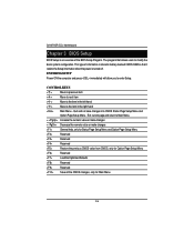
Exit current page and return to enter Setup. GA-8IPXDR-E(C) Motherboard Chapter 3 BIOS Setup BIOS Setup is stored in the right hand Main Menu - The program that it retains the Setup information when the power ...
Exit current page and return to enter Setup. GA-8IPXDR-E(C) Motherboard Chapter 3 BIOS Setup BIOS Setup is stored in the right hand Main Menu - The program that it retains the Setup information when the power ...

