User Manual
Page 2
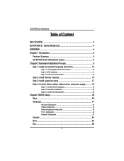
... of Content Item Checklist 4 GA-8IPXDR-E Series Model List 4 WARNING 4 Chapter 1 Introduction 6 Features Summary 6 GA-8IPXDR-E(C) Motherboard Layout 8 Chapter 2 Hardware Installation Process 9 Step 1: Install the Central Processing Unit (CPU 10 Step 1-1: Installing Motherboard to the Chassis 10 Step 1-2: CPU Installation 11 Step 1-3: CPU Heat Sink Installation 13 Step 2: Install memory modules 15 Step 3: Install expansion...
... of Content Item Checklist 4 GA-8IPXDR-E Series Model List 4 WARNING 4 Chapter 1 Introduction 6 Features Summary 6 GA-8IPXDR-E(C) Motherboard Layout 8 Chapter 2 Hardware Installation Process 9 Step 1: Install the Central Processing Unit (CPU 10 Step 1-1: Installing Motherboard to the Chassis 10 Step 1-2: CPU Installation 11 Step 1-3: CPU Heat Sink Installation 13 Step 2: Install memory modules 15 Step 3: Install expansion...
User Manual
Page 6
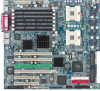
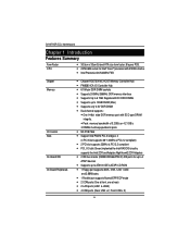
...ATAPI devices y Supports up to ATA100 IDE & ATAPI CD-ROM y 1 Floppy port supports 360K, 720K,1.2M, 1.44M and 2.88M bytes. GA-8IPXDR-E(C) Motherboard Chapter 1 Introduction Features Summary Form Factor CPU y 30.5cm x 33cm Extend ATX size form factor, 8 layers PCB. y 1 Parallel port ...512KB L2cache y Intel Prestonia 400/533MHz FSB Chipset Memory I/O Control Slots On-Board IDE On-Board Peripherals y Chipset RGE7501MC HOST/Memory Controller Hub y FW82801CA I/O Controller Hub y 6 184-pin DDR DIMM sockets y Supports 200MHz/266MHz DDR memory interface y Supports Up to 6 72bit Registered ECC ...
...ATAPI devices y Supports up to ATA100 IDE & ATAPI CD-ROM y 1 Floppy port supports 360K, 720K,1.2M, 1.44M and 2.88M bytes. GA-8IPXDR-E(C) Motherboard Chapter 1 Introduction Features Summary Form Factor CPU y 30.5cm x 33cm Extend ATX size form factor, 8 layers PCB. y 1 Parallel port ...512KB L2cache y Intel Prestonia 400/533MHz FSB Chipset Memory I/O Control Slots On-Board IDE On-Board Peripherals y Chipset RGE7501MC HOST/Memory Controller Hub y FW82801CA I/O Controller Hub y 6 184-pin DDR DIMM sockets y Supports 200MHz/266MHz DDR memory interface y Supports Up to 6 72bit Registered ECC ...

User Manual
Page 9
Connect ribbon cables, cabinet wires, and power supply Step 5- Setup BIOS software Step 6- Install the Central Processing Unit (CPU) Step 2- Install memory modules Step 3- Install expansion cards Step 4- Install supporting software tools Step 4 Step 5 Step 4 Step1 Step 4 Step 3 Step 4 Step 4 Step 4 Step 2 9 Hardware Installation Process Chapter 2 Hardware Installation Process To set up your computer, you must complete the following setups: Step 1-
Connect ribbon cables, cabinet wires, and power supply Step 5- Setup BIOS software Step 6- Install the Central Processing Unit (CPU) Step 2- Install memory modules Step 3- Install expansion cards Step 4- Install supporting software tools Step 4 Step 5 Step 4 Step1 Step 4 Step 3 Step 4 Step 4 Step 4 Step 2 9 Hardware Installation Process Chapter 2 Hardware Installation Process To set up your computer, you must complete the following setups: Step 1-

User Manual
Page 15
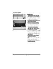
To install the memory module, just push it can vary between sockets. Registered DDR Notch J4 (B-1) J1 (A-1) J5 (B-2) J2 (A-2) J6 (B-3) J3 (A-3) 15 Hardware Installation Process Step 2: Install memory modules The motherboard has 6 dual inline memory module (DIMM) sockets, but it vertically into the DIMM Slot .The DIMM module can only fit in one direction due to the notch.Memory size can only support a maximum of 3 banks DDR memory. DDR socket 1 uses 1 bank, DDR socket 2& 3 share the remaining 2 banks. The BIOS will automatically detects memory type and size.
To install the memory module, just push it can vary between sockets. Registered DDR Notch J4 (B-1) J1 (A-1) J5 (B-2) J2 (A-2) J6 (B-3) J3 (A-3) 15 Hardware Installation Process Step 2: Install memory modules The motherboard has 6 dual inline memory module (DIMM) sockets, but it vertically into the DIMM Slot .The DIMM module can only fit in one direction due to the notch.Memory size can only support a maximum of 3 banks DDR memory. DDR socket 1 uses 1 bank, DDR socket 2& 3 share the remaining 2 banks. The BIOS will automatically detects memory type and size.
User Manual
Page 16
... number sequence are J3J6 -- J1J4. If you must insert it down. 3. Insert the DIMM memory module vertically into DIMM module. Reverse the installation steps when you want to remove the DIMM module. 16 GA-8IPXDR-E(C) Motherboard J4 (B-1) J1 (A-1) J5 (B-2) J2 (A-2) J6 (B-3) J3 (A-3) Installation Step: 1. ...The DIMM slot has a notch, so the DIMM memory module can only fit in J3/J6 slot. 5. If you wish...
... number sequence are J3J6 -- J1J4. If you must insert it down. 3. Insert the DIMM memory module vertically into DIMM module. Reverse the installation steps when you want to remove the DIMM module. 16 GA-8IPXDR-E(C) Motherboard J4 (B-1) J1 (A-1) J5 (B-2) J2 (A-2) J6 (B-3) J3 (A-3) Installation Step: 1. ...The DIMM slot has a notch, so the DIMM memory module can only fit in J3/J6 slot. 5. If you wish...
User Manual
Page 40
Off If a hard disk has not been installed select NONE and press . System Information This category displays the following system information: the Processor type, Speed, Cache Size, Total Memory Size, Memory Resized DIMM, BIOS version, BIOS Release Date and System Product Name. 40 GA-8IPXDR-E(C) Motherboard Fast Programmed I/O Mode This field only shows the information of Fast Programmed I/O Mode. 32 Bit Transfer Mode Enables 32 bit access to maximize the hard disk data transfer rate. Option: On (Default Value);
Off If a hard disk has not been installed select NONE and press . System Information This category displays the following system information: the Processor type, Speed, Cache Size, Total Memory Size, Memory Resized DIMM, BIOS version, BIOS Release Date and System Product Name. 40 GA-8IPXDR-E(C) Motherboard Fast Programmed I/O Mode This field only shows the information of Fast Programmed I/O Mode. 32 Bit Transfer Mode Enables 32 bit access to maximize the hard disk data transfer rate. Option: On (Default Value);

User Manual
Page 54
... be asked to 6 characters in lengh and press . Set Supervisor Password You can install and change this option. 54 Type the password again and press . GA-8IPXDR-E(C) Motherboard Security AMI BIOS NEW SETUP Utility - Type the password up to confirm the entered password. You will clear any previously entered password from the...
... be asked to 6 characters in lengh and press . Set Supervisor Password You can install and change this option. 54 Type the password again and press . GA-8IPXDR-E(C) Motherboard Security AMI BIOS NEW SETUP Utility - Type the password up to confirm the entered password. You will clear any previously entered password from the...

User Manual
Page 55
... 6 characters in creating a password. Password Check ` Setup will check password while invlolking setup. (Default Value) ` Always will clear any previously entered password from the CMOS memory. BIOS Setup Set User Password You can only enter but do not have the right to change the options of the screen o assist you select...
... 6 characters in creating a password. Password Check ` Setup will check password while invlolking setup. (Default Value) ` Always will clear any previously entered password from the CMOS memory. BIOS Setup Set User Password You can only enter but do not have the right to change the options of the screen o assist you select...
User Manual
Page 68
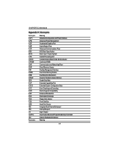
GA-8IPXDR-E(C) Motherboard Appendix H: Acronyms Acronyms ACPI APM AGP AMR ACR BBS BIOS CPU CMOS CRIMM CNR DMA DMI DIMM DRM DRAM DDR ECP ESCD ECC EMC ... Basic Input / Output System Central Processing Unit Complementary Metal Oxide Semiconductor Continuity RIMM Communication and Networking Riser Direct Memory Access Desktop Management Interface Dual Inline Memory Module Dual Retention Mechanism Dynamic Random Access Memory Double Data Rate Extended Capabilities Port Extended System Configuration Data Error Checking and Correcting Electromagnetic Compatibility Enhanced Parallel Port...
GA-8IPXDR-E(C) Motherboard Appendix H: Acronyms Acronyms ACPI APM AGP AMR ACR BBS BIOS CPU CMOS CRIMM CNR DMA DMI DIMM DRM DRAM DDR ECP ESCD ECC EMC ... Basic Input / Output System Central Processing Unit Complementary Metal Oxide Semiconductor Continuity RIMM Communication and Networking Riser Direct Memory Access Desktop Management Interface Dual Inline Memory Module Dual Retention Mechanism Dynamic Random Access Memory Double Data Rate Extended Capabilities Port Extended System Configuration Data Error Checking and Correcting Electromagnetic Compatibility Enhanced Parallel Port...


