User Manual
Page 2
...GA-8IPXDR-E(C) Motherboard Layout 8 Chapter 2 Hardware Installation Process 9 Step 1: Install the Central Processing Unit (CPU 10 Step 1-1: Installing Motherboard to the Chassis 10 Step 1-2: CPU Installation 11 Step 1-3: CPU Heat Sink Installation 13 Step 2: Install memory modules 15 Step 3: Install expansion cards 17 Step 4: Connect ribbon cables, cabinet wires, and power supply 18 Step 4-1: I/O Back Panel Introduction 18 Step 4-2: Connectors Introduction 20 Step 4-3: Jumper Setting Introduction 30 Chapter 3 BIOS Setup 36 Main ...38 Advanced 41 Advanced Configuration 42 Chipset...
...GA-8IPXDR-E(C) Motherboard Layout 8 Chapter 2 Hardware Installation Process 9 Step 1: Install the Central Processing Unit (CPU 10 Step 1-1: Installing Motherboard to the Chassis 10 Step 1-2: CPU Installation 11 Step 1-3: CPU Heat Sink Installation 13 Step 2: Install memory modules 15 Step 3: Install expansion cards 17 Step 4: Connect ribbon cables, cabinet wires, and power supply 18 Step 4-1: I/O Back Panel Introduction 18 Step 4-2: Connectors Introduction 20 Step 4-3: Jumper Setting Introduction 30 Chapter 3 BIOS Setup 36 Main ...38 Advanced 41 Advanced Configuration 42 Chipset...
User Manual
Page 3
Table of Content Chapter 4 Technical Reference 60 GA-8IPXDR-E System Block Diagram 60 Chapter 5 Appendix 61 Appendix A: Intel Network Driver Installation 61 Appendix B: INF Update Installation (Driver for chipset 63 Appendix C: ATI Rage XL VGA Driver Installation 64 Appexdix D: Adaptec SCSI Driver Installation 65 Appendix E: Utilites Installation 66 Appendix F: About Updateing Latest version of BIOS 66 Appendix G: IPMI Connector Pin Definition 67 Appendix H: Acronyms 68 Technical Support/RMA Sheet 70 3
Table of Content Chapter 4 Technical Reference 60 GA-8IPXDR-E System Block Diagram 60 Chapter 5 Appendix 61 Appendix A: Intel Network Driver Installation 61 Appendix B: INF Update Installation (Driver for chipset 63 Appendix C: ATI Rage XL VGA Driver Installation 64 Appexdix D: Adaptec SCSI Driver Installation 65 Appendix E: Utilites Installation 66 Appendix F: About Updateing Latest version of BIOS 66 Appendix G: IPMI Connector Pin Definition 67 Appendix H: Acronyms 68 Technical Support/RMA Sheet 70 3
User Manual
Page 4
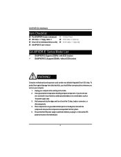
... the ATX power supply is switched off before handling computer components. To protect them against damage from the system. 5. Unplug your hands to a safely grounded object or to a metal object, such as the power supply case. 3. Computer motherboards and expansion cards contain very delicate Integrated Circuit (IC) chips. USB Cable x 1(Optional) ; The GA-8IPXDR-E series motherboard ; Driver CD for motherboard driver & utility ; Place components on a grounded antistatic pad or on the inside. 2. IDE cable x 1/ Floppy cable x 1 ; GA-8IPXDR-E(C) Motherboard...
... the ATX power supply is switched off before handling computer components. To protect them against damage from the system. 5. Unplug your hands to a safely grounded object or to a metal object, such as the power supply case. 3. Computer motherboards and expansion cards contain very delicate Integrated Circuit (IC) chips. USB Cable x 1(Optional) ; The GA-8IPXDR-E series motherboard ; Driver CD for motherboard driver & utility ; Place components on a grounded antistatic pad or on the inside. 2. IDE cable x 1/ Floppy cable x 1 ; GA-8IPXDR-E(C) Motherboard...
User Manual
Page 6
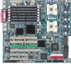
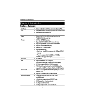
... type DRAM integrity. y 1 Parallel port supports Normal/EPP/ECP mode y 2 COM ports (One at front, one at rear) y 2 LAN ports (LAN1 & LAN2) y 4 USB ports (Rear USB x 2, Front USB x 2) 6 y mPGA 604 socket for up to 4 ATAPI devices y Supports up to 12GB DRAM (Max) y Supports only 2.5V DDR DIMM y Dual channel supports : y One 144bit wide DDR memory port with 512KB L2cache y Intel Prestonia 400/533MHz FSB Chipset Memory I/O Control Slots On-Board IDE On-Board Peripherals y Chipset RGE7501MC HOST/Memory Controller Hub y FW82801CA I/O Controller Hub y 6 184-pin...
... type DRAM integrity. y 1 Parallel port supports Normal/EPP/ECP mode y 2 COM ports (One at front, one at rear) y 2 LAN ports (LAN1 & LAN2) y 4 USB ports (Rear USB x 2, Front USB x 2) 6 y mPGA 604 socket for up to 4 ATAPI devices y Supports up to 12GB DRAM (Max) y Supports only 2.5V DDR DIMM y Dual channel supports : y One 144bit wide DDR memory port with 512KB L2cache y Intel Prestonia 400/533MHz FSB Chipset Memory I/O Control Slots On-Board IDE On-Board Peripherals y Chipset RGE7501MC HOST/Memory Controller Hub y FW82801CA I/O Controller Hub y 6 184-pin...

User Manual
Page 7
... controller (Server Adapter) On-Board VGA y Build in ATI Rage XL PCI VGA Chipset On-Board SCSI y Adaptec 7902W Ultra 320 SCSI Chipset PS/2 Connector y PS/2 Keyboard interface and PS/2 Mouse interace BIOS y Licensed AMI BIOS, 4M bit FWH Additional Features y Wake on your processor's specifications. Introduction Hardware Monitor y CPU/Power/System Fan Revolution detect y CPU Overheat Warning y System Voltage Detect On-Board LAN y Build in Intel 82546EB single chip with your hardware configurations, including CPU, Chipsets,SDRAM,Cards...
... controller (Server Adapter) On-Board VGA y Build in ATI Rage XL PCI VGA Chipset On-Board SCSI y Adaptec 7902W Ultra 320 SCSI Chipset PS/2 Connector y PS/2 Keyboard interface and PS/2 Mouse interace BIOS y Licensed AMI BIOS, 4M bit FWH Additional Features y Wake on your processor's specifications. Introduction Hardware Monitor y CPU/Power/System Fan Revolution detect y CPU Overheat Warning y System Voltage Detect On-Board LAN y Build in Intel 82546EB single chip with your hardware configurations, including CPU, Chipsets,SDRAM,Cards...
User Manual
Page 10
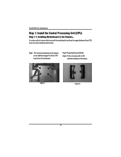
Step2: Preparing the assemblt kits. Figure 1 Figure 2 10 GA-8IPXDR-E(C) Motherboard Step 1: Install the Central Processing Unit (CPU) Step 1-1: Installing Motherboard to reinforce the support between Xeon CPU heat-sink on the mainboard and chassis. You may use the 4 screws which come with 2 CPU retention modules on the mainboard. Step1: The 4 new mounting holes on the chassis are for additional support for Xeon CPU heat-sink on the chassis. Step3: Fit the 4 screws with the mainboard to the Chassis...
Step2: Preparing the assemblt kits. Figure 1 Figure 2 10 GA-8IPXDR-E(C) Motherboard Step 1: Install the Central Processing Unit (CPU) Step 1-1: Installing Motherboard to reinforce the support between Xeon CPU heat-sink on the mainboard and chassis. You may use the 4 screws which come with 2 CPU retention modules on the mainboard. Step1: The 4 new mounting holes on the chassis are for additional support for Xeon CPU heat-sink on the chassis. Step3: Fit the 4 screws with the mainboard to the Chassis...
User Manual
Page 12
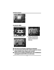
... CPU socket lever and finish CPU installation. Locate Pin 1 in the socket and look for a (golden) cut edge well, it will cause improper installation. Please change the insert orientation. 0 Warning: If your are installing one CPU ONLY, please refer to the Motherboard Layout (page 8) to install the CPU into the socket. 3. Pin1 indicator 2. GA-8IPXDR-E(C) Motherboard 3. Press down the CPU socket lever and finish CPU installation. 0 Please make sure the CPU type is supported by the motherboard...
... CPU socket lever and finish CPU installation. Locate Pin 1 in the socket and look for a (golden) cut edge well, it will cause improper installation. Please change the insert orientation. 0 Warning: If your are installing one CPU ONLY, please refer to the Motherboard Layout (page 8) to install the CPU into the socket. 3. Pin1 indicator 2. GA-8IPXDR-E(C) Motherboard 3. Press down the CPU socket lever and finish CPU installation. 0 Please make sure the CPU type is supported by the motherboard...

User Manual
Page 15
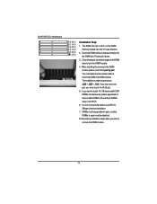
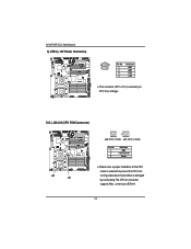
To install the memory module, just push it can vary between sockets. Hardware Installation Process Step 2: Install memory modules The motherboard has 6 dual inline memory module (DIMM) sockets, but it vertically into the DIMM Slot .The DIMM module can only fit in one direction due to the notch.Memory size can only support a maximum of 3 banks DDR memory. Registered DDR Notch J4 (B-1) J1 (A-1) J5 (B-2) J2 (A-2) J6 (B-3) J3 (A-3) 15 The BIOS will automatically detects memory type and size. DDR socket 1 uses 1 bank, DDR socket 2& 3 share the remaining 2 banks.
To install the memory module, just push it can vary between sockets. Hardware Installation Process Step 2: Install memory modules The motherboard has 6 dual inline memory module (DIMM) sockets, but it vertically into the DIMM Slot .The DIMM module can only fit in one direction due to the notch.Memory size can only support a maximum of 3 banks DDR memory. Registered DDR Notch J4 (B-1) J1 (A-1) J5 (B-2) J2 (A-2) J6 (B-3) J3 (A-3) 15 The BIOS will automatically detects memory type and size. DDR socket 1 uses 1 bank, DDR socket 2& 3 share the remaining 2 banks.
User Manual
Page 16
... away from MCH. 6. Reverse the installation steps when you must be identical. 8. GA-8IPXDR-E(C) Motherboard J4 (B-1) J1 (A-1) J5 (B-2) J2 (A-2) J6 (B-3) J3 (A-3) Installation Step: 1. Insert the DIMM memory module vertically into DIMM module. When installing the memoryin the DIMM module, please insert them pair by pair. J1J4. Then push it in J3/J6 slot. 5. J2J5 -- If you only insert...
... away from MCH. 6. Reverse the installation steps when you must be identical. 8. GA-8IPXDR-E(C) Motherboard J4 (B-1) J1 (A-1) J5 (B-2) J2 (A-2) J6 (B-3) J3 (A-3) Installation Step: 1. Insert the DIMM memory module vertically into DIMM module. When installing the memoryin the DIMM module, please insert them pair by pair. J1J4. Then push it in J3/J6 slot. 5. J2J5 -- If you only insert...
User Manual
Page 18
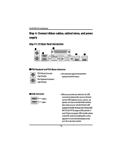
... patch or driver upgrade. Have a standard USB interface. Y USB Connector USB 0 USB 1 ¾Before you connect your device(s) into USB connector(s), please make sure your device(s) such as USB keyboard, mouse, scanner, zip, speaker..etc. Also make sure your OS (Win 95 with USB supplement, Win98, Windows 2000, Windows ME, Win NT with SP 6) supports USB controller. GA-8IPXDR-E(C) Motherboard Step 4: Connect ribbon cables, cabinet wires, and power supply Step 4-1: I/O Back Panel Introduction X Z Y [ \ X PS/2 Keyboard and PS/2 Mouse Connector PS/2 Mouse Connector (6 pin Female) PS...
... patch or driver upgrade. Have a standard USB interface. Y USB Connector USB 0 USB 1 ¾Before you connect your device(s) into USB connector(s), please make sure your device(s) such as USB keyboard, mouse, scanner, zip, speaker..etc. Also make sure your OS (Win 95 with USB supplement, Win98, Windows 2000, Windows ME, Win NT with SP 6) supports USB controller. GA-8IPXDR-E(C) Motherboard Step 4: Connect ribbon cables, cabinet wires, and power supply Step 4-1: I/O Back Panel Introduction X Z Y [ \ X PS/2 Keyboard and PS/2 Mouse Connector PS/2 Mouse Connector (6 pin Female) PS...
User Manual
Page 22
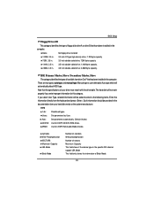
O/Q ) J30/J32 (CPU FAN Connector) J32 J30 1 1 J32:CPU1 FAN J30:CPU 0 FAN Pin No. 1 2 3 Definition GND +12v/Control Sense ¾Please note, a proper installation of the CPU cooler is used only for CPU Core Voltage. current up to prevent the CPU from running under abnormal condition or damaged by overheating.The CPU fan connector supports Max. GA-8IPXDR-E(C) Motherboard C) ATX2 (+12V Power Connector) 43 21 Pin No. 1 2 3 4 Definition GND GND +12V +12V ¾This connector (ATX +12V) is essential to 600mA . 22
O/Q ) J30/J32 (CPU FAN Connector) J32 J30 1 1 J32:CPU1 FAN J30:CPU 0 FAN Pin No. 1 2 3 Definition GND +12v/Control Sense ¾Please note, a proper installation of the CPU cooler is used only for CPU Core Voltage. current up to prevent the CPU from running under abnormal condition or damaged by overheating.The CPU fan connector supports Max. GA-8IPXDR-E(C) Motherboard C) ATX2 (+12V Power Connector) 43 21 Pin No. 1 2 3 4 Definition GND GND +12V +12V ¾This connector (ATX +12V) is essential to 600mA . 22
User Manual
Page 39
... been installed in the computer. Auto: Set parameters automatically. (Default Vaules) CD/DVD: Use for this category. There are two types: auto type, and manual type. Manual type is user-definable; Note that the specifications of your hard disk vendor or the system manufacturer. TYPE 1-46: Predefined types. Auto type which will be provided in the documentation form your drive must match with the drive table. If you enter improper information for ATAPI CD/DVD-ROM drives...
... been installed in the computer. Auto: Set parameters automatically. (Default Vaules) CD/DVD: Use for this category. There are two types: auto type, and manual type. Manual type is user-definable; Note that the specifications of your hard disk vendor or the system manufacturer. TYPE 1-46: Predefined types. Auto type which will be provided in the documentation form your drive must match with the drive table. If you enter improper information for ATAPI CD/DVD-ROM drives...
User Manual
Page 42
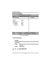
GA-8IPXDR-E(C) Motherboard Advanced Configuration AMI BIOS NEW SETUP Utility - The indicates DISPLAY ONLY 42 VERSION 3.31a Main Advanced Security Boot Exit Advanced Configuration [Setup Help] Quick Boot MPS Version for O.S Console Redirect C.R Baud Rate C.R after Post Disabled 1.4 Disabled 19200 Disabled F1: Help Esc: Exit KL: Select Item IJ: Select Menu + -: Change Values F5: Setup Defaults Enter: Select Sub-Menu F10: Save&Exit Figure 2-1: Advanced Configuration Advanced Configuration ` Quick Boot This setting allows BIOS to skip certain tests while booting. (Default ...
GA-8IPXDR-E(C) Motherboard Advanced Configuration AMI BIOS NEW SETUP Utility - The indicates DISPLAY ONLY 42 VERSION 3.31a Main Advanced Security Boot Exit Advanced Configuration [Setup Help] Quick Boot MPS Version for O.S Console Redirect C.R Baud Rate C.R after Post Disabled 1.4 Disabled 19200 Disabled F1: Help Esc: Exit KL: Select Item IJ: Select Menu + -: Change Values F5: Setup Defaults Enter: Select Sub-Menu F10: Save&Exit Figure 2-1: Advanced Configuration Advanced Configuration ` Quick Boot This setting allows BIOS to skip certain tests while booting. (Default ...
User Manual
Page 47
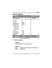
VERSION 3.31a Main Advanced Security Boot Exit Peripheral Configuration BIOS Setup [Setup Help] OnBoard IDE Both OnBoard FDC Enabled Onboard Serial Port A Onboard Serial Port B 3F8/COM1 2F8/COM2 Onboard Parallel Port 378 Parallel Port Mode ECP Parallel Port IRQ 7 Parallel Port DMA 3 USB Function Enabled USB Legacy Support Disabled OnBoard Gigabit LAN Enabled OnBoard SCSI F1: Help Esc: Exit Enabled KL: Select Item IJ: Select Menu + -: Change Values F5: Setup Defaults Enter: Select Sub-Menu F10: Save&Exit Figure 2-5: Peripheral Configuration Peripheral ...
VERSION 3.31a Main Advanced Security Boot Exit Peripheral Configuration BIOS Setup [Setup Help] OnBoard IDE Both OnBoard FDC Enabled Onboard Serial Port A Onboard Serial Port B 3F8/COM1 2F8/COM2 Onboard Parallel Port 378 Parallel Port Mode ECP Parallel Port IRQ 7 Parallel Port DMA 3 USB Function Enabled USB Legacy Support Disabled OnBoard Gigabit LAN Enabled OnBoard SCSI F1: Help Esc: Exit Enabled KL: Select Item IJ: Select Menu + -: Change Values F5: Setup Defaults Enter: Select Sub-Menu F10: Save&Exit Figure 2-5: Peripheral Configuration Peripheral ...
User Manual
Page 49
... The parallel port can be used . Enable Enable USB host controller (Default Value) Disabled Disable this setting to select Parallel Port DMA. ECP provides the symmetric bi-directional communication. (Default value) ` Parallel Port IRQ This option is used with devices that adhere to the enhanced Parallel Port ( EPP ) specifications. Enabled Enables support for legacy USB Disabled Disables support for legacy USB. EPP The parallel port can be used with devices that adhere to the extended Capabilities Port specifications. Normal The normal parallel pro is...
... The parallel port can be used . Enable Enable USB host controller (Default Value) Disabled Disable this setting to select Parallel Port DMA. ECP provides the symmetric bi-directional communication. (Default value) ` Parallel Port IRQ This option is used with devices that adhere to the enhanced Parallel Port ( EPP ) specifications. Enabled Enables support for legacy USB Disabled Disables support for legacy USB. EPP The parallel port can be used with devices that adhere to the extended Capabilities Port specifications. Normal The normal parallel pro is...

User Manual
Page 54
... password again and press . The password typed now will be asked to confirm the entered password. You may also press to abort the selection and not enter a specified password or press key to 6 characters in lengh and press . Type the password up to disable this option. 54 In addition, user also can set the virus protection for different level of password securities. GA-8IPXDR-E(C) Motherboard Security AMI BIOS NEW SETUP Utility...
... password again and press . The password typed now will be asked to confirm the entered password. You may also press to abort the selection and not enter a specified password or press key to 6 characters in lengh and press . Type the password up to disable this option. 54 In addition, user also can set the virus protection for different level of password securities. GA-8IPXDR-E(C) Motherboard Security AMI BIOS NEW SETUP Utility...
User Manual
Page 56
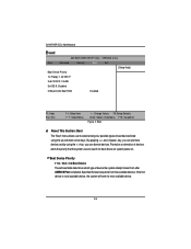
VERSION 3.31a Main Advanced Security Boot Exit [Setup Help] Boot Device Priority 1st Floppy: 1.44 MB 31/2 2nd CD/DVD: C-540E 3rd IDE-0: Disabled OnBoard LAN Boot ROM Disabled F1: Help Esc: Exit KL: Select Item IJ: Select Menu + -: Change Values F5: Setup Defaults Enter: Select Sub-Menu F10: Save&Exit Figure 4: Boot * About This Section: Boot The "Boot" menu allows user to select among four possible types of boot devices listed using the key, you can demote devices. By applying and key, you can...
VERSION 3.31a Main Advanced Security Boot Exit [Setup Help] Boot Device Priority 1st Floppy: 1.44 MB 31/2 2nd CD/DVD: C-540E 3rd IDE-0: Disabled OnBoard LAN Boot ROM Disabled F1: Help Esc: Exit KL: Select Item IJ: Select Menu + -: Change Values F5: Setup Defaults Enter: Select Sub-Menu F10: Save&Exit Figure 4: Boot * About This Section: Boot The "Boot" menu allows user to select among four possible types of boot devices listed using the key, you can demote devices. By applying and key, you can...
User Manual
Page 64
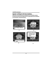
If not, please double click the CD-ROM device icon in "My computer", and execute the setup.exe. 2.Click "Next". 1.Click "ATI Rage XL VGA Driver" item. (1) (2) 4. Select "Yes, I want to restart my computer" item and click "Finish" to restart computer. 3.Click "Yes" at License Agreement window. (3) (4) 64 GA-8IPXDR-E(C) Motherboard Appendix C: ATI Rage XL VGA Driver Installation Insert the driver CD-title that came with your motherboard into your CD-ROM driver, the driver CD-title will auto start and show the installation guide.
If not, please double click the CD-ROM device icon in "My computer", and execute the setup.exe. 2.Click "Next". 1.Click "ATI Rage XL VGA Driver" item. (1) (2) 4. Select "Yes, I want to restart my computer" item and click "Finish" to restart computer. 3.Click "Yes" at License Agreement window. (3) (4) 64 GA-8IPXDR-E(C) Motherboard Appendix C: ATI Rage XL VGA Driver Installation Insert the driver CD-title that came with your motherboard into your CD-ROM driver, the driver CD-title will auto start and show the installation guide.
User Manual
Page 65
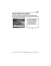
Click in "My computer", and execute the setup.exe. 2. A n exploer window will pops up screen will auto start and show the installation guide. If not, please double click the CD-ROM device icon in the "SCSI 7902W" folder, the followed up . Appendix Appexdix D: Adaptec SCSI Driver Installation Insert the driver CD-title that came with your motherboard into your CD-ROM driver, the driver CD-title will guide you to install the SCSI driver depends on the operating system. 1. Click "Adaptec SCSI Driver" item. (1) (2) 65
Click in "My computer", and execute the setup.exe. 2. A n exploer window will pops up screen will auto start and show the installation guide. If not, please double click the CD-ROM device icon in the "SCSI 7902W" folder, the followed up . Appendix Appexdix D: Adaptec SCSI Driver Installation Insert the driver CD-title that came with your motherboard into your CD-ROM driver, the driver CD-title will guide you to install the SCSI driver depends on the operating system. 1. Click "Adaptec SCSI Driver" item. (1) (2) 65
User Manual
Page 66
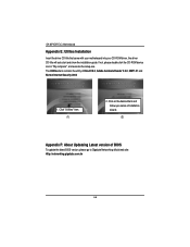
... installation wizard. (2) Appendix F: About Updateing Latest version of DirectX 9.0, Adabe Acrobate Reader V.5.0, GMT1.21 and Norton Internet Security 2003 1. GA-8IPXDR-E(C) Motherboard Appendix E: Utilites Installation Insert the driver CD-title that came with your motherboard into your CD-ROM driver, the driver CD-title will auto start and show the installation guide. If not, please double click the CD-ROM device icon in "My computer", and execute the setup...
... installation wizard. (2) Appendix F: About Updateing Latest version of DirectX 9.0, Adabe Acrobate Reader V.5.0, GMT1.21 and Norton Internet Security 2003 1. GA-8IPXDR-E(C) Motherboard Appendix E: Utilites Installation Insert the driver CD-title that came with your motherboard into your CD-ROM driver, the driver CD-title will auto start and show the installation guide. If not, please double click the CD-ROM device icon in "My computer", and execute the setup...


