Manual
Page 4
...GA-8IP775(-G) Motherboard Layout 6 Block Diagram ...7 Chapter 1 Hardware Installation 9 1-1 Considerations Prior to Installation 9 1-2 Feature Summary 10 1-3 Installation of the CPU and Heatsink 12 1-3-1 Installation of the CPU 12 1-3-2 Installation of the Heatsink 13 1-4 Installation of Memory 14 1-5 Installation of Expansion Cards 16 1-6 I/O Back Panel Introduction 17 1-7 Connectors Introduction 18 Chapter 2 BIOS... Setup 29 The Main Menu (For example: BIOS Ver. : E2 30 2-1 Standard CMOS Features 32 2-2 Advanced BIOS Features 34 2-3 Integrated ...
...GA-8IP775(-G) Motherboard Layout 6 Block Diagram ...7 Chapter 1 Hardware Installation 9 1-1 Considerations Prior to Installation 9 1-2 Feature Summary 10 1-3 Installation of the CPU and Heatsink 12 1-3-1 Installation of the CPU 12 1-3-2 Installation of the Heatsink 13 1-4 Installation of Memory 14 1-5 Installation of Expansion Cards 16 1-6 I/O Back Panel Introduction 17 1-7 Connectors Introduction 18 Chapter 2 BIOS... Setup 29 The Main Menu (For example: BIOS Ver. : E2 30 2-1 Standard CMOS Features 32 2-2 Advanced BIOS Features 34 2-3 Integrated ...
Manual
Page 5
Chapter 3 Install Drivers 51 3-1 Install Chipset Drivers 51 3-2 Software Applications 52 3-3 Driver CD Information 52 3-4 Hardware Information 53 3-5 Contact Us ...53 Chapter 4 Appendix 55 4-1 Unique Software Utilities 55 4-1-1 Xpress Recovery Introduction 55 4-1-2 Flash BIOS Method Introduction 58 4-1-3 2 / 4 / 6 / 8 Channel Audio Function Introduction 67 4-1-4 Jack-Sensing and UAJ Introduction 73 4-2 Troubleshooting 75 - 5 -
Chapter 3 Install Drivers 51 3-1 Install Chipset Drivers 51 3-2 Software Applications 52 3-3 Driver CD Information 52 3-4 Hardware Information 53 3-5 Contact Us ...53 Chapter 4 Appendix 55 4-1 Unique Software Utilities 55 4-1-1 Xpress Recovery Introduction 55 4-1-2 Flash BIOS Method Introduction 58 4-1-3 2 / 4 / 6 / 8 Channel Audio Function Introduction 67 4-1-4 Jack-Sensing and UAJ Introduction 73 4-2 Troubleshooting 75 - 5 -
Manual
Page 6
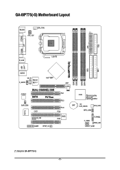
GA-8IP775(-G) Motherboard Layout KB_MS CPU_FAN ATX_12V COMA FDD ATX COMB LPT R_USB LGA775 IDE1 IDE2 GA-8IP775(-G) DDR1 DDR2 USB LAN (*) AUDIO CD_IN Intel® 865P Marvell F_AUDIO 8001 (*) AGP DDR4 DDR3 IT8712 CODEC SUR_CEN DUAL CHANNEL DDR PCI1 SATA P4 Titan PCI2 CI IR_CIR PCI3 PCI4 BIOS PCI5 GAME SPDIF_IO ICH5 SATA1 SATA0 BAT CLR_CMOS SYS_FAN INFO_LINK F_PANEL F_USB2 PWR_LED F_USB1 (*) Only for GA-8IP775-G. - 6 -
GA-8IP775(-G) Motherboard Layout KB_MS CPU_FAN ATX_12V COMA FDD ATX COMB LPT R_USB LGA775 IDE1 IDE2 GA-8IP775(-G) DDR1 DDR2 USB LAN (*) AUDIO CD_IN Intel® 865P Marvell F_AUDIO 8001 (*) AGP DDR4 DDR3 IT8712 CODEC SUR_CEN DUAL CHANNEL DDR PCI1 SATA P4 Titan PCI2 CI IR_CIR PCI3 PCI4 BIOS PCI5 GAME SPDIF_IO ICH5 SATA1 SATA0 BAT CLR_CMOS SYS_FAN INFO_LINK F_PANEL F_USB2 PWR_LED F_USB1 (*) Only for GA-8IP775-G. - 6 -
Manual
Page 7
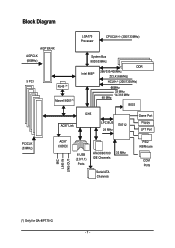
Block Diagram AGP 8X/4X AGPCLK (66MHz) 5 PCI RJ45 (*) Marvell 8001(*) AC97 Link LGA775 Processor CPUCLK+/- (200/133MHz) System Bus 800/533MHz DDR Intel 865P 266/333/400MHz ZCLK (66MHz) HCLK+/- (200/133MHz) 66MHz 33 MHz 48 MHz 14.318 MHz BIOS ICH5 LPC BUS IT8712 24 MHz Game Port Floppy LPT Port PCICLK (33MHz) MIC LINE-IN LINE-OUT AC97 CODEC 8 USB (2.0/1.1) Ports ATA33/66/100 33 MHz IDE Channels Serial ATA Channels PS/2 KB/Mouse COM Ports (*) Only for GA-8IP775-G. - 7 -
Block Diagram AGP 8X/4X AGPCLK (66MHz) 5 PCI RJ45 (*) Marvell 8001(*) AC97 Link LGA775 Processor CPUCLK+/- (200/133MHz) System Bus 800/533MHz DDR Intel 865P 266/333/400MHz ZCLK (66MHz) HCLK+/- (200/133MHz) 66MHz 33 MHz 48 MHz 14.318 MHz BIOS ICH5 LPC BUS IT8712 24 MHz Game Port Floppy LPT Port PCICLK (33MHz) MIC LINE-IN LINE-OUT AC97 CODEC 8 USB (2.0/1.1) Ports ATA33/66/100 33 MHz IDE Channels Serial ATA Channels PS/2 KB/Mouse COM Ports (*) Only for GA-8IP775-G. - 7 -

Manual
Page 11
Hardware Installation English I/O Control Hardware Monitor BIOS Additional Features Overclocking Form Factor w IT8712 w System voltage detection w CPU temperature detection w CPU / System fan speed detection w CPU warning temperature w CPU / Systemfan failure warning w CPU sm art fan control w Use of licensed AWARD BIOS w Supports Q-Flash w Supports @BIOS w Supports EasyTune w Over Voltage via BIOS (CPU/DDR/AGP) w Over Clock via BIOS (CPU/DDR/AGP/PCI) w ATX form factor; 30.5cm x 24.4cm - 11 -
Hardware Installation English I/O Control Hardware Monitor BIOS Additional Features Overclocking Form Factor w IT8712 w System voltage detection w CPU temperature detection w CPU / System fan speed detection w CPU warning temperature w CPU / Systemfan failure warning w CPU sm art fan control w Use of licensed AWARD BIOS w Supports Q-Flash w Supports @BIOS w Supports EasyTune w Over Voltage via BIOS (CPU/DDR/AGP) w Over Clock via BIOS (CPU/DDR/AGP/PCI) w ATX form factor; 30.5cm x 24.4cm - 11 -
Manual
Page 12
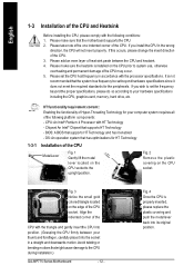
... that the motherboard supports the CPU. 2. HT functionality requirement content : Enabling the functionality of Hyper-Threading Technology for the peripherals. BIOS: A BIOS that the system bus frequency be set the CPU host frequency in the wrong direction, the CPU will not insert properly. Fig...the insert direction of the CPU. Fig. 2 Rem ov e the pl astic covering on the CPU socket to the CPU during installation.) GA-8IP775 Series Motherboard - 12 - Please add an even layer of heat sink paste between your hardware specifications including the CPU, graphics card, memory...
... that the motherboard supports the CPU. 2. HT functionality requirement content : Enabling the functionality of Hyper-Threading Technology for the peripherals. BIOS: A BIOS that the system bus frequency be set the CPU host frequency in the wrong direction, the CPU will not insert properly. Fig...the insert direction of the CPU. Fig. 2 Rem ov e the pl astic covering on the CPU socket to the CPU during installation.) GA-8IP775 Series Motherboard - 12 - Please add an even layer of heat sink paste between your hardware specifications including the CPU, graphics card, memory...
Manual
Page 14
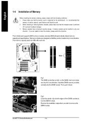
... capacity used . 2. The motherboard supports DDR memory modules, whereby BIOS will automatically detect memory capacity and specifications. Fig.2 Close the plastic clip at both edges of the DIMM sockets to prevent hardware damage. 3. A memory module can be inserted only in one direction. GA-8IP775 Series Motherboard - 14 - English 1-4 Installation of similar capacity, specifications...
... capacity used . 2. The motherboard supports DDR memory modules, whereby BIOS will automatically detect memory capacity and specifications. Fig.2 Close the plastic clip at both edges of the DIMM sockets to prevent hardware damage. 3. A memory module can be inserted only in one direction. GA-8IP775 Series Motherboard - 14 - English 1-4 Installation of similar capacity, specifications...
Manual
Page 16
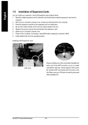
Press the expansion card firmly into the com puter. 2. Power on the computer, if necessary, setup BIOS utility of expansion card from the operating system. Please align the VGA card to the onboard AGP slot and press firmly down on the card ... slot in the slot. 5. Install related driver from BIOS. 8. Installing a AGP expansion card: AGP Card Please carefully pull out the small white-drawable bar at the end of the AGP slot when you try to secure the slot bracket of the expansion card. 6. GA-8IP775 Series Motherboard - 16 - Replace your computer's chassis cover...
Press the expansion card firmly into the com puter. 2. Power on the computer, if necessary, setup BIOS utility of expansion card from the operating system. Please align the VGA card to the onboard AGP slot and press firmly down on the card ... slot in the slot. 5. Install related driver from BIOS. 8. Installing a AGP expansion card: AGP Card Please carefully pull out the small white-drawable bar at the end of the AGP slot when you try to secure the slot bracket of the expansion card. 6. GA-8IP775 Series Motherboard - 16 - Replace your computer's chassis cover...
Manual
Page 21
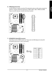
Please connect the red power connector wire to work properly. Please refer to the BIOS setting for the Serial ATA and install the proper driver in order to the pin1 position. 34 33 2 1 7) SATA0/SATA1 (Serial ATAConnector) Serial ATA can ...
Please connect the red power connector wire to work properly. Please refer to the BIOS setting for the Serial ATA and install the proper driver in order to the pin1 position. 34 33 2 1 7) SATA0/SATA1 (Serial ATAConnector) Serial ATA can ...

Manual
Page 27
Pin No. To clear CMOS, temporarily short 1-2 pin. Hardware Installation English 18) CI (Chassis Intrusion, Case Open) This 2-pin connector allows your system to its default values by this jumper. 1 Open:Normal 1 Short:Clear CMOS - 27 - Definition 1 1 Signal 2 GND 19) CLR_CMOS (Clear CMOS) You may clear the CMOS data to enable or disable the "Case Open" item in BIOS, if the system casebegin remove. Default doesn't include the "Shunter" to prevent from improper use this jumper.
Pin No. To clear CMOS, temporarily short 1-2 pin. Hardware Installation English 18) CI (Chassis Intrusion, Case Open) This 2-pin connector allows your system to its default values by this jumper. 1 Open:Normal 1 Short:Clear CMOS - 27 - Definition 1 1 Signal 2 GND 19) CLR_CMOS (Clear CMOS) You may clear the CMOS data to enable or disable the "Case Open" item in BIOS, if the system casebegin remove. Default doesn't include the "Shunter" to prevent from improper use this jumper.
Manual
Page 29
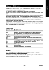
...Page Setup Menu Load the file-safe default CMOS value from the Internet. Quit and not save the current BIOS to DOS before upgrading BIOS but directly download and update BIOS from BIOS default table Load the Optimized Defaults Q-Flash utility System Information Save all the CMOS changes, only for the ...Menu Main Menu The on-line description of the highlighted setup function is turned on the motherboard supplies the necessary power to a new BIOS, either Gigabyte's Q-Flash or @BIOS utility can enter the BIOS setup screen by pressing "Ctrl + F1". If you to its original settings...
...Page Setup Menu Load the file-safe default CMOS value from the Internet. Quit and not save the current BIOS to DOS before upgrading BIOS but directly download and update BIOS from BIOS default table Load the Optimized Defaults Q-Flash utility System Information Save all the CMOS changes, only for the ...Menu Main Menu The on-line description of the highlighted setup function is turned on the motherboard supplies the necessary power to a new BIOS, either Gigabyte's Q-Flash or @BIOS utility can enter the BIOS setup screen by pressing "Ctrl + F1". If you to its original settings...
Manual
Page 30
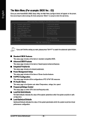
GA-8IP775 Series Motherboard - 30 - Use arrow keys to select among the items and press to search the advanced option hidden. „ Standard CMOS Features This setup page includes all the items in standard compatible BIOS. „ Advanced BIOS Features This setup page includes all the... which the system would be in best performance configuration. CMOS Setup Utility-Copyright (C) 1984-2004 Award Software ` Standard CMOS Features ` Advanced BIOS Features ` Integrated Peripherals ` Power Management Setup ` PnP/PCI Configurations ` PC Health Status ` Frequency/Voltage Control ESC: Quit F8: Q-...
GA-8IP775 Series Motherboard - 30 - Use arrow keys to select among the items and press to search the advanced option hidden. „ Standard CMOS Features This setup page includes all the items in standard compatible BIOS. „ Advanced BIOS Features This setup page includes all the... which the system would be in best performance configuration. CMOS Setup Utility-Copyright (C) 1984-2004 Award Software ` Standard CMOS Features ` Advanced BIOS Features ` Integrated Peripherals ` Power Management Setup ` PnP/PCI Configurations ` PC Health Status ` Frequency/Voltage Control ESC: Quit F8: Q-...

Manual
Page 31
BIOS Setup It allows you to limit access to the system. „ Save & Exit Setup Save CMOS value settings to Setup. „ Set User Password Change, set , or disable password. It allows you to limit access to the system and Setup, or just to CMOS and exit setup. „ Exit Without Saving Abandon all CMOS value changes and exit setup. - 31 - English „ Set Supervisor Password Change, set , or disable password.
BIOS Setup It allows you to limit access to the system. „ Save & Exit Setup Save CMOS value settings to Setup. „ Set User Password Change, set , or disable password. It allows you to limit access to the system and Setup, or just to CMOS and exit setup. „ Exit Without Saving Abandon all CMOS value changes and exit setup. - 31 - English „ Set Supervisor Password Change, set , or disable password.
Manual
Page 32
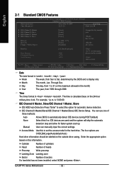
... of cylinders Head Number of heads Precomp Write precomp Landing Zone Landing zone Sector Number of three methods: Auto None Allows BIOS to set the access mode for the hard drive. GA-8IP775 Series Motherboard - 32 - Through Dec. to Sat. The time is , , , . IDE Channel 0 Master, Slave/IDE Channel 1 Master, Slave...time clock. Jan. Week Month The week, from 1999 through 2098 Time The times format in the month) 1999 to Sat, determined by the BIOS and is 13:00:00. is display only The month, Jan. User can use one of sectors If a hard disk has not been installed,...
... of cylinders Head Number of heads Precomp Write precomp Landing Zone Landing zone Sector Number of three methods: Auto None Allows BIOS to set the access mode for the hard drive. GA-8IP775 Series Motherboard - 32 - Through Dec. to Sat. The time is , , , . IDE Channel 0 Master, Slave/IDE Channel 1 Master, Slave...time clock. Jan. Week Month The week, from 1999 through 2098 Time The times format in the month) 1999 to Sat, determined by the BIOS and is 13:00:00. is display only The month, Jan. User can use one of sectors If a hard disk has not been installed,...
Manual
Page 33
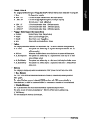
...Errors The system boot will determine the amount of base (or conventional) memory installed in the computer. Base Memory The POST of the BIOS will not stop for any error that may be detected and you will be prompted. English Drive A / Drive B The category identifies ...; 1.44M byte capacity. 2.88M, 3.5" 3.5 inch double-sided drive; 2.88M byte capacity. Both Drive A & B are 3 mode Floppy Drives. All Errors Whenever the BIOS detects a non-fatal error the system will be stopped. it will stop for all other errors. (Default value) All, But Diskette The system boot will...
...Errors The system boot will determine the amount of base (or conventional) memory installed in the computer. Base Memory The POST of the BIOS will not stop for any error that may be detected and you will be prompted. English Drive A / Drive B The category identifies ...; 1.44M byte capacity. 2.88M, 3.5" 3.5 inch double-sided drive; 2.88M byte capacity. Both Drive A & B are 3 mode Floppy Drives. All Errors Whenever the BIOS detects a non-fatal error the system will be stopped. it will stop for all other errors. (Default value) All, But Diskette The system boot will...
Manual
Page 34
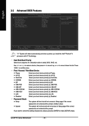
...Disk Boot Priority Select boot sequence for onboard(or add-on cards) SCSI, RAID, etc. USB-ZIP Select your boot device priority by Hard Disk. GA-8IP775 Series Motherboard - 34 - USB-HDD Select your boot device priority by Floppy. to 3 [Press Enter] [Floppy] [Hard Disk] [CDROM] [...not boot and will detect automatically and show up , or to exit this menu. English 2-2 Advanced BIOS Features CMOS Setup Utility-Copyright (C) 1984-2004 Award Software Advanced BIOS Features X Hard Disk Boot Priority First Boot Device Second Boot Device Third Boot Device Password Check # ...
...Disk Boot Priority Select boot sequence for onboard(or add-on cards) SCSI, RAID, etc. USB-ZIP Select your boot device priority by Hard Disk. GA-8IP775 Series Motherboard - 34 - USB-HDD Select your boot device priority by Floppy. to 3 [Press Enter] [Floppy] [Hard Disk] [CDROM] [...not boot and will detect automatically and show up , or to exit this menu. English 2-2 Advanced BIOS Features CMOS Setup Utility-Copyright (C) 1984-2004 Award Software Advanced BIOS Features X Hard Disk Boot Priority First Boot Device Second Boot Device Third Boot Device Password Check # ...

Manual
Page 35
English CPU Hyper-Threading Enabled Enables CPU Hyper Threading Feature. Limit CPUID Max. BIOS Setup to 3 Enabled Disabled Limit CPUID Maximum value to 3 when use older OS like NT4. (Default value) Disables CPUID Limit for operating system with multi processors mode supported. (Default value) Disables CPU Hyper Threading. Please note that this feature is only working Disabled for windows XP. - 35 -
English CPU Hyper-Threading Enabled Enables CPU Hyper Threading Feature. Limit CPUID Max. BIOS Setup to 3 Enabled Disabled Limit CPUID Maximum value to 3 when use older OS like NT4. (Default value) Disables CPUID Limit for operating system with multi processors mode supported. (Default value) Disables CPU Hyper Threading. Please note that this feature is only working Disabled for windows XP. - 35 -
Manual
Page 37
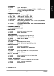
...) Disabled Disable USB Controller. Onboard H/W LAN (*) Enabled Enable Onboard H/W LAN function. (Default value) Disabled Disable this function. (*) Only for GA-8IP775-G. - 37 - Slave Remap SATA Port 0 to IDE Pri. As this mode, it support by WinXP or later OS only. USB Keyboard ... using onboard USB 2.0 feature. SATA Port0 Configure as The values depend on SATA Port0. USB 2.0 Controller Disable this function. BIOS Setup English On-chip SATA Disabled Disable SATA controller. Disabled Disable USB Keyboard Support. (Default value) USB Mouse Support Enabled Enable...
...) Disabled Disable USB Controller. Onboard H/W LAN (*) Enabled Enable Onboard H/W LAN function. (Default value) Disabled Disable this function. (*) Only for GA-8IP775-G. - 37 - Slave Remap SATA Port 0 to IDE Pri. As this mode, it support by WinXP or later OS only. USB Keyboard ... using onboard USB 2.0 feature. SATA Port0 Configure as The values depend on SATA Port0. USB 2.0 Controller Disable this function. BIOS Setup English On-chip SATA Disabled Disable SATA controller. Disabled Disable USB Keyboard Support. (Default value) USB Mouse Support Enabled Enable...

Manual
Page 38
English Onboard Serial Port 1 Auto BIOS will automatically setup the port 1 address. 3F8/IRQ4 2F8/IRQ3 Enable onboard Serial port 1 and address is 3F8. (Default value) Enable onboard Serial port 1 and .... ECP Using Parallel port as ECP & EPP mode. Enable onboard Serial port 2 and address is 3F8. Disabled Disable onboard Serial port 2. GA-8IP775 Series Motherboard - 38 - Onboard Serial Port 2 Auto BIOS will available when "UART Mode Select" doesn't set at Normal. UR2 Duplex Mode This feature allows you to determine which Infra Red...
English Onboard Serial Port 1 Auto BIOS will automatically setup the port 1 address. 3F8/IRQ4 2F8/IRQ3 Enable onboard Serial port 1 and address is 3F8. (Default value) Enable onboard Serial port 1 and .... ECP Using Parallel port as ECP & EPP mode. Enable onboard Serial port 2 and address is 3F8. Disabled Disable onboard Serial port 2. GA-8IP775 Series Motherboard - 38 - Onboard Serial Port 2 Auto BIOS will available when "UART Mode Select" doesn't set at Normal. UR2 Duplex Mode This feature allows you to determine which Infra Red...

Manual
Page 41
... left button to the system, the system always in "Off" state. (Default value) Full-On Memory When AC-power back to power on the system. BIOS Setup AC Back Function Soft-Off When AC-power back to the system, the system will return to set at Password, you can set the...
... left button to the system, the system always in "Off" state. (Default value) Full-On Memory When AC-power back to power on the system. BIOS Setup AC Back Function Soft-Off When AC-power back to the system, the system will return to set at Password, you can set the...


