Manual
Page 1
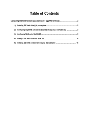
Table of Contents Configuring IDE RAID Hard Drive(s) (Controller GigaRAID (IT8212 2 (1) Installing IDE hard drive(s) in your system 2 (2) Configuring GigaRAID controller mode and boot sequence in BIOS Setup 3 (3) Configuring RAID set in RAID BIOS 5 (4) Making a IDE RAID controller driver disk 14 (5) Installing IDE RAID controller driver during OS installation 16
Table of Contents Configuring IDE RAID Hard Drive(s) (Controller GigaRAID (IT8212 2 (1) Installing IDE hard drive(s) in your system 2 (2) Configuring GigaRAID controller mode and boot sequence in BIOS Setup 3 (3) Configuring RAID set in RAID BIOS 5 (4) Making a IDE RAID controller driver disk 14 (5) Installing IDE RAID controller driver during OS installation 16
Manual
Page 2
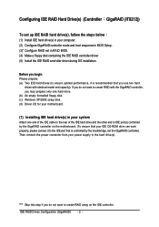
Then connect the power connector from your computer. (2) Configure GigaRAID controller mode and boot sequence in BIOS Setup. (3)* Configure RAID set in RAID BIOS. (4) Make a floppy disk containing the IDE RAID controller driver (5) Install the IDE RAID controller driver during OS installation. "*" Skip this step if you do not ...
Then connect the power connector from your computer. (2) Configure GigaRAID controller mode and boot sequence in BIOS Setup. (3)* Configure RAID set in RAID BIOS. (4) Make a floppy disk containing the IDE RAID controller driver (5) Install the IDE RAID controller driver during OS installation. "*" Skip this step if you do not ...
Manual
Page 3
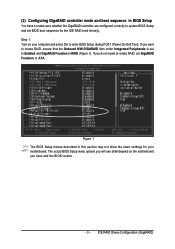
...Value F10: Save F6: Fail-Safe Defaults Figure 1 ESC: Exit F1: General Help F7: Optimized Defaults The BIOS Setup menus described in system BIOS Setup and set BIOS boot sequence for your computer and press Del to make sure whether the GigaRAID controller are configured correctly in this ...show the exact settings for the IDE RAID hard drive(s). (2) Configuring GigaRAID controller mode and boot sequence in BIOS Setup You have and the BIOS version . - 3 - The actual BIOS Setup menu options you will see shall depend on your motherboard. Step 1: Turn on the motherboard you have...
...Value F10: Save F6: Fail-Safe Defaults Figure 1 ESC: Exit F1: General Help F7: Optimized Defaults The BIOS Setup menus described in system BIOS Setup and set BIOS boot sequence for your computer and press Del to make sure whether the GigaRAID controller are configured correctly in this ...show the exact settings for the IDE RAID hard drive(s). (2) Configuring GigaRAID controller mode and boot sequence in BIOS Setup You have and the BIOS version . - 3 - The actual BIOS Setup menu options you will see shall depend on your motherboard. Step 1: Turn on the motherboard you have...
Manual
Page 4
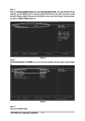
...IDE hard drive onto which you can boot from Installation CD after system restarts.(Figure 3) CMOS Setup Utility-Copyright (C) 1984-2004 Award Software Advanced BIOS Features : Move Enter: Select F5: Previous Values +/-/PU/PD: Value F10: Save F6: Fail-Safe Defaults Figure 3 ESC: Exit F1: ...General Help F7: Optimized Defaults Step 4 Save and exit BIOS Setup. Ác Step 2 Next, go to the first item. IDE RAID Drives Configuration (GigaRAID) - 4 - In the Hard Disk Boot Priority Å...
...IDE hard drive onto which you can boot from Installation CD after system restarts.(Figure 3) CMOS Setup Utility-Copyright (C) 1984-2004 Award Software Advanced BIOS Features : Move Enter: Select F5: Previous Values +/-/PU/PD: Value F10: Save F6: Fail-Safe Defaults Figure 3 ESC: Exit F1: ...General Help F7: Optimized Defaults Step 4 Save and exit BIOS Setup. Ác Step 2 Next, go to the first item. IDE RAID Drives Configuration (GigaRAID) - 4 - In the Hard Disk Boot Priority Å...
Manual
Page 5
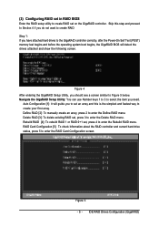
... drives to the GigaRAID controller correctly, after the Power-On Self Test (POST) memory test begins and before the operating system boot begins, the GigaRAID BIOS will guide you to set on the GigaRAID controller. Rebuild RAID [4]: To rebuild RAID 1 or RAID 0+1 set , press 3 to enter the Delete RAID menu. Delete... RAID [3]: To delete existing RAID set , press 4 to enter the Rebuild RAID menu. (3) Configuring RAID set in RAID BIOS Enter the RAID setup utility to create RAID set an array and this step and proceed to Section 4 if you do not want to create...
... drives to the GigaRAID controller correctly, after the Power-On Self Test (POST) memory test begins and before the operating system boot begins, the GigaRAID BIOS will guide you to set on the GigaRAID controller. Rebuild RAID [4]: To rebuild RAID 1 or RAID 0+1 set , press 3 to enter the Delete RAID menu. Delete... RAID [3]: To delete existing RAID set , press 4 to enter the Rebuild RAID menu. (3) Configuring RAID set in RAID BIOS Enter the RAID setup utility to create RAID set an array and this step and proceed to Section 4 if you do not want to create...
Manual
Page 16
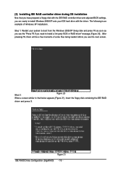
... Drives Configuration (GigaRAID) - 16 - Step 2: Figure 20 When a screen similar to that you have prepared a floppy disk with the IDE RAID controller driver and adjusted BIOS settings, you are ready to boot from the Windows 2000/XP Setup disk and press F6 as soon as you see the "Press F6 if...
... Drives Configuration (GigaRAID) - 16 - Step 2: Figure 20 When a screen similar to that you have prepared a floppy disk with the IDE RAID controller driver and adjusted BIOS settings, you are ready to boot from the Windows 2000/XP Setup disk and press F6 as soon as you see the "Press F6 if...
Manual
Page 9
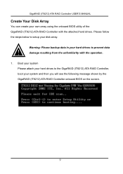
...the attached hard drives. GigaRAID (IT8212) ATA RAID Controller USER'S MANUAL Create Your Disk Array You can create your own array using the onboard BIOS utility of the GigaRAID (IT8212) ATA RAID Controller with the operation. 1. Warning: Please backup data in your hard drives to the GigaRAID (IT8212...) ATA RAID Controller, boot your system and then you will see the following message shown by the GigaRAID (IT8212) ATA RAID Controller onboard BIOS on the screen. 9 Boot your system Please attach your disk array. Please follow the steps below to setup your hard drives to prevent data...
...the attached hard drives. GigaRAID (IT8212) ATA RAID Controller USER'S MANUAL Create Your Disk Array You can create your own array using the onboard BIOS utility of the GigaRAID (IT8212) ATA RAID Controller with the operation. 1. Warning: Please backup data in your hard drives to the GigaRAID (IT8212...) ATA RAID Controller, boot your system and then you will see the following message shown by the GigaRAID (IT8212) ATA RAID Controller onboard BIOS on the screen. 9 Boot your system Please attach your disk array. Please follow the steps below to setup your hard drives to prevent data...
Manual
Page 10
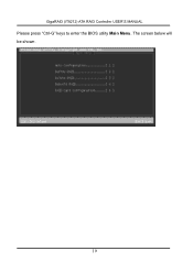
The screen below will be shown. 10 GigaRAID (IT8212) ATA RAID Controller USER'S MANUAL Please press "Ctrl-G" keys to enter the BIOS utility Main Menu.
The screen below will be shown. 10 GigaRAID (IT8212) ATA RAID Controller USER'S MANUAL Please press "Ctrl-G" keys to enter the BIOS utility Main Menu.
Manual
Page 14
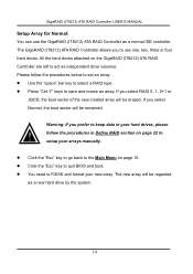
... GigaRAID (IT8212) ATA RAID Controller are left to keep data in your arrays manually. You need to select a RAID type. Warning: If you to quit BIOS and boot. If you select Normal, the boot sector will be remained. All the hard drives attached on page 22 to setup your hard drives...
... GigaRAID (IT8212) ATA RAID Controller are left to keep data in your arrays manually. You need to select a RAID type. Warning: If you to quit BIOS and boot. If you select Normal, the boot sector will be remained. All the hard drives attached on page 22 to setup your hard drives...
Manual
Page 15
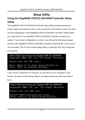
...) ATA RAID Controller. Please attach your array's configuration is incorrect, you will see the following message shown by the GigaRAID (IT8212) ATA RAID Controller onboard BIOS on your system. If your hard drives to boot. 15
...) ATA RAID Controller. Please attach your array's configuration is incorrect, you will see the following message shown by the GigaRAID (IT8212) ATA RAID Controller onboard BIOS on your system. If your hard drives to boot. 15
Manual
Page 88
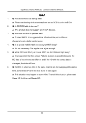
... time, sometimes AP can two RAID0 perform well? To avoid this situation, please set Slave HD first then set RAID as SCSI boot in the BIOS. 2. Q: How to get a better performance. 4. Q: What if R1 and R0+1 just create RAID but don't Rebuild right away?
... time, sometimes AP can two RAID0 perform well? To avoid this situation, please set Slave HD first then set RAID as SCSI boot in the BIOS. 2. Q: How to get a better performance. 4. Q: What if R1 and R0+1 just create RAID but don't Rebuild right away?

Manual
Page 5
Table of Contents GA-8I955X Royal/GA-8I955X Pro Motherboard Layout 7 Block Diagram ...8 Chapter 1 Hardware Installation 9 1-1 Considerations Prior to Installation 9 1-2 Feature Summary 10 1-3 Installation of the CPU and...DPS (Universal Plus Dual Power System 17 1-8 I/O Back Panel Introduction 18 1-9 Connectors Introduction 19 Chapter 2 BIOS Setup 29 The Main Menu (For example: BIOS Ver. : GA-8I955X Royal F6c 30 2-1 Standard CMOS Features 32 2-2 Advanced BIOS Features 34 2-3 IntegratedPeripherals 36 2-4 Power Management Setup 39 2-5 PnP/PCI Configurations 40 2-6 PC Health Status 41...
Table of Contents GA-8I955X Royal/GA-8I955X Pro Motherboard Layout 7 Block Diagram ...8 Chapter 1 Hardware Installation 9 1-1 Considerations Prior to Installation 9 1-2 Feature Summary 10 1-3 Installation of the CPU and...DPS (Universal Plus Dual Power System 17 1-8 I/O Back Panel Introduction 18 1-9 Connectors Introduction 19 Chapter 2 BIOS Setup 29 The Main Menu (For example: BIOS Ver. : GA-8I955X Royal F6c 30 2-1 Standard CMOS Features 32 2-2 Advanced BIOS Features 34 2-3 IntegratedPeripherals 36 2-4 Power Management Setup 39 2-5 PnP/PCI Configurations 40 2-6 PC Health Status 41...

Manual
Page 6
Channel Audio Function Introduction 77 4-2 Troubleshooting 82 Only for Dolby® Master StudioTM 75 4-1-6 2- / 4- / 6- / 8- Chapter 3 Drivers Installation 49 3-1 Install Chipset Drivers 49 3-2 SoftwareApplications 50 3-3 Driver CD Information 50 3-4 Hardware Information 51 3-5 Contact Us ...51 Chapter 4 Appendix 53 4-1 Unique Software Utilities 53 4-1-1 EasyTune 5 Introduction 54 4-1-2 Xpress Recovery2 Introduction 55 4-1-3 Flash BIOS Method Introduction 57 4-1-4 Serial ATA BIOS Setting Utility Introduction 68 4-1-5 Introduction of Designed for GA-8I955X Royal. - 6 -
Channel Audio Function Introduction 77 4-2 Troubleshooting 82 Only for Dolby® Master StudioTM 75 4-1-6 2- / 4- / 6- / 8- Chapter 3 Drivers Installation 49 3-1 Install Chipset Drivers 49 3-2 SoftwareApplications 50 3-3 Driver CD Information 50 3-4 Hardware Information 51 3-5 Contact Us ...51 Chapter 4 Appendix 53 4-1 Unique Software Utilities 53 4-1-1 EasyTune 5 Introduction 54 4-1-2 Xpress Recovery2 Introduction 55 4-1-3 Flash BIOS Method Introduction 57 4-1-4 Serial ATA BIOS Setting Utility Introduction 68 4-1-5 Introduction of Designed for GA-8I955X Royal. - 6 -
Manual
Page 7
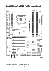
Only for GA-8I955X Royal. GA-8I955X Royal/GA-8I955X Pro Motherboard Layout KB_MS SPDIF_O SPDIFO_OPT VRM_CONN LGA775 CPU_FAN IT8712F ATX COMA LPT GA-8I955X Royal (Pro) PWR_FAN LAN1 LAN2 USB USB AUDIO1 ATX_12V_2X4 AUDIO2 Broadcom 5751 phy F_AUDIO PCIE_16 Broadcom 5751 / 5789 phy PCI1 NB_FAN PCI2 Intel® 955X CLR_CMOS ...SN082AA2 SN081BA3 F1_1394 F2_1394 IT8212F F_USB IDE2 IDE3 SPDIF_I ESATAII1 ESATAII0 GREEN_USB DDRII1 DDRII2 DDRII3 DDRII4 FDD IDE1 CI SATAII3 SATAII2 SATAII1 SATAII0 SYS_FAN Main BIOS Backup BIOS PWR_LED F_PANEL Only for GA-8I955X Pro. - 7 -
Only for GA-8I955X Royal. GA-8I955X Royal/GA-8I955X Pro Motherboard Layout KB_MS SPDIF_O SPDIFO_OPT VRM_CONN LGA775 CPU_FAN IT8712F ATX COMA LPT GA-8I955X Royal (Pro) PWR_FAN LAN1 LAN2 USB USB AUDIO1 ATX_12V_2X4 AUDIO2 Broadcom 5751 phy F_AUDIO PCIE_16 Broadcom 5751 / 5789 phy PCI1 NB_FAN PCI2 Intel® 955X CLR_CMOS ...SN082AA2 SN081BA3 F1_1394 F2_1394 IT8212F F_USB IDE2 IDE3 SPDIF_I ESATAII1 ESATAII0 GREEN_USB DDRII1 DDRII2 DDRII3 DDRII4 FDD IDE1 CI SATAII3 SATAII2 SATAII1 SATAII0 SYS_FAN Main BIOS Backup BIOS PWR_LED F_PANEL Only for GA-8I955X Pro. - 7 -
Manual
Page 8
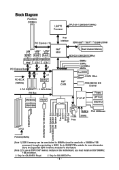
Only for GA-8I955X Pro. - 8 - Only for GA-8I955X Royal. Go to 888MHz (must install an 800/1066MHz FSB processor. Block Diagram PCI-...(Note 2)/533MHz DIMM Intel® Dual Channel Memory 955X MCHCLK (266/200/133MHz) 66MHz 33MHz 14.318MHz 48MHz Dual BIOS 4 SATA 3Gb/s Intel® ICH7R ATA33/66/100 IDE Channel CODEC IT 8712F Floppy LPT Port COM Port 8 ...Line-Out Line-In SPDIF In SPDIF Out 3 PCI PCICLK(33MHz) (Note 1) DDR II memory can be overclocked to GIGABYTE's website for more information about the supported DDR II memory modules for this feature. (Note 2) To use a DDR...
Only for GA-8I955X Pro. - 8 - Only for GA-8I955X Royal. Go to 888MHz (must install an 800/1066MHz FSB processor. Block Diagram PCI-...(Note 2)/533MHz DIMM Intel® Dual Channel Memory 955X MCHCLK (266/200/133MHz) 66MHz 33MHz 14.318MHz 48MHz Dual BIOS 4 SATA 3Gb/s Intel® ICH7R ATA33/66/100 IDE Channel CODEC IT 8712F Floppy LPT Port COM Port 8 ...Line-Out Line-In SPDIF In SPDIF Out 3 PCI PCICLK(33MHz) (Note 1) DDR II memory can be overclocked to GIGABYTE's website for more information about the supported DDR II memory modules for this feature. (Note 2) To use a DDR...

Manual
Page 10
... Line Out (Front Speaker Out) ; Only for GA-8I955X Pro. GA-8I955X Royal/GA-8I955X Pro Motherboard - 10 - MIC ; Only for GA-8I955X Royal. Supported on the motherboard, you must be used...Side Speaker Out connection (Note 1) For further CPU support information, please go to GIGABYTE's website. (Note 2) Due to 8GB memory)(Note 2) Supports dual channel DDR II...GA-8I955X Pro Supports LGA775 Intel® Pentium® Processor Extreme Edition/ Pentium® D / Pentium® 4 (Note 1) Supports 1066/800/533MHz FSB L2 cache varies with a 1066MHz FSB processor) through overclocking in BIOS...
... Line Out (Front Speaker Out) ; Only for GA-8I955X Pro. GA-8I955X Royal/GA-8I955X Pro Motherboard - 10 - MIC ; Only for GA-8I955X Royal. Supported on the motherboard, you must be used...Side Speaker Out connection (Note 1) For further CPU support information, please go to GIGABYTE's website. (Note 2) Due to 8GB memory)(Note 2) Supports dual channel DDR II...GA-8I955X Pro Supports LGA775 Intel® Pentium® Processor Extreme Edition/ Pentium® D / Pentium® 4 (Note 1) Supports 1066/800/533MHz FSB L2 cache varies with a 1066MHz FSB processor) through overclocking in BIOS...

Manual
Page 11
... function - Only for GA-8I955X Royal. Hardware Installation supports a maximum of 4 SATA 3Gb/s connections - Only for GA-8I955X Pro. - 11 - supports ATA133/RAID mode switch by BIOS - features LBA and Extended Interrupt 13 drive translation in controller onboard BIOS Onboard Intel® ICH7R... Hardware Monitor Š Š Š Š Š Š Onboard IDE RAID Š Onboard SATA 3Gb/s Š RAID Š BIOS Š Š Additional Features Š Š Š Overclocking Š Š Form Factor Š SPDIF In connection SPDIF Out connection (...
... function - Only for GA-8I955X Royal. Hardware Installation supports a maximum of 4 SATA 3Gb/s connections - Only for GA-8I955X Pro. - 11 - supports ATA133/RAID mode switch by BIOS - features LBA and Extended Interrupt 13 drive translation in controller onboard BIOS Onboard Intel® ICH7R... Hardware Monitor Š Š Š Š Š Š Onboard IDE RAID Š Onboard SATA 3Gb/s Š RAID Š BIOS Š Š Additional Features Š Š Š Overclocking Š Š Form Factor Š SPDIF In connection SPDIF Out connection (...
Manual
Page 12
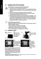
... sure that has optimizations for the peripherals. CPU: An Intel® Pentium 4 Processor with the following platform components: - BIOS: A BIOS that the system bus frequency be set the frequency beyond hardware specifications since it enabled - Please take note of the one indented...Installation of the CPU Metal Lever Fig. 1 Gently lift the metal lever located on the CPU prior to the CPU during installation.) GA-8I955X Royal/GA-8I955X Pro Motherboard - 12 - English 1-3 Installation of the CPU and Heatsink Before installing the CPU, please comply with HT Technology - ...
... sure that has optimizations for the peripherals. CPU: An Intel® Pentium 4 Processor with the following platform components: - BIOS: A BIOS that the system bus frequency be set the frequency beyond hardware specifications since it enabled - Please take note of the one indented...Installation of the CPU Metal Lever Fig. 1 Gently lift the metal lever located on the CPU prior to the CPU during installation.) GA-8I955X Royal/GA-8I955X Pro Motherboard - 12 - English 1-3 Installation of the CPU and Heatsink Before installing the CPU, please comply with HT Technology - ...
Manual
Page 14
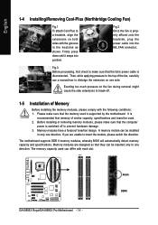
... of Memory Before installing the memory modules, please comply with each slot. The motherboard supports DDR II memory modules, whereby BIOS will automatically detect memory capacity and specifications. The memory capacity used can be used is recommended that they can be inserted..., please switch the direction. If you are designed so that memory of similar capacity, specifications and brand be installed in only one direction. GA-8I955X Royal/GA-8I955X Pro Motherboard - 14 - Notch DDR II Fig.2 Once the fan is switched off . 1-5 Installation of the fan, carefully use a ...
... of Memory Before installing the memory modules, please comply with each slot. The motherboard supports DDR II memory modules, whereby BIOS will automatically detect memory capacity and specifications. The memory capacity used can be used is recommended that they can be inserted..., please switch the direction. If you are designed so that memory of similar capacity, specifications and brand be installed in only one direction. GA-8I955X Royal/GA-8I955X Pro Motherboard - 14 - Notch DDR II Fig.2 Once the fan is switched off . 1-5 Installation of the fan, carefully use a ...

Manual
Page 16
...chassis cover, screws and slot bracket from the computer. 3. English 1-6 Installation of Expansion Cards You can install your computer's chassis cover. 7. GA-8I955X Royal/GA-8I955X Pro Motherboard - 16 - Be sure the metal contacts on the slot. When you try uninstall the VGA card, please gently press the latch... system. Press the expansion card firmly into the computer. 2. Power on the computer, if necessary, setup BIOS utility of the expansion card. 6. Install related driver from BIOS. 8. Replace your expansion card by the latch at the end of the PCI Express x 16 slot. ...
...chassis cover, screws and slot bracket from the computer. 3. English 1-6 Installation of Expansion Cards You can install your computer's chassis cover. 7. GA-8I955X Royal/GA-8I955X Pro Motherboard - 16 - Be sure the metal contacts on the slot. When you try uninstall the VGA card, please gently press the latch... system. Press the expansion card firmly into the computer. 2. Power on the computer, if necessary, setup BIOS utility of the expansion card. 6. Install related driver from BIOS. 8. Replace your expansion card by the latch at the end of the PCI Express x 16 slot. ...


