Manual
Page 4
Table of Contents ItemChecklist ...6 OptionalAccessories ...6 GA-8I945GZME-RH Motherboard Layout 7 Block Diagram ...8 Chapter 1 Hardware Installation 9 1-1 Considerations Prior to Installation 9 1-2 Feature Summary 10 1-3 Installation of the CPU ...15 1-5-1 Graphics Card Support List 16 1-6 I/O Back Panel Introduction 17 1-7 Connectors Introduction 18 Chapter 2 BIOS Setup 29 The Main Menu (For example: BIOS Ver. : E7 30 2-1 Standard CMOS Features 32 2-2 Advanced BIOS Features 34 2-3 IntegratedPeripherals 36 2-4 Power Management Setup 39 2-5 PnP/PCI Configurations 41 2-6 PC Health ...
Table of Contents ItemChecklist ...6 OptionalAccessories ...6 GA-8I945GZME-RH Motherboard Layout 7 Block Diagram ...8 Chapter 1 Hardware Installation 9 1-1 Considerations Prior to Installation 9 1-2 Feature Summary 10 1-3 Installation of the CPU ...15 1-5-1 Graphics Card Support List 16 1-6 I/O Back Panel Introduction 17 1-7 Connectors Introduction 18 Chapter 2 BIOS Setup 29 The Main Menu (For example: BIOS Ver. : E7 30 2-1 Standard CMOS Features 32 2-2 Advanced BIOS Features 34 2-3 IntegratedPeripherals 36 2-4 Power Management Setup 39 2-5 PnP/PCI Configurations 41 2-6 PC Health ...

Manual
Page 5
Channel Audio Introduction 65 4-2 Troubleshooting 71 - 5 - Chapter 3 Install Drivers 49 3-1 Install Chipset Drivers 49 3-2 SoftwareApplications 50 3-3 Driver CD Information 50 3-4 Hardware Information 51 3-5 Contact Us ...51 Chapter 4 Appendix 53 4-1 Unique Software Utilities 53 4-1-1 EasyTune 5 Introduction 53 4-1-2 Xpress Recovery2 Introduction 54 4-1-3 Flash BIOS Method Introduction 56 4-1-4 2- / 4- / 6- / 8-
Channel Audio Introduction 65 4-2 Troubleshooting 71 - 5 - Chapter 3 Install Drivers 49 3-1 Install Chipset Drivers 49 3-2 SoftwareApplications 50 3-3 Driver CD Information 50 3-4 Hardware Information 51 3-5 Contact Us ...51 Chapter 4 Appendix 53 4-1 Unique Software Utilities 53 4-1-1 EasyTune 5 Introduction 53 4-1-2 Xpress Recovery2 Introduction 54 4-1-3 Flash BIOS Method Introduction 56 4-1-4 2- / 4- / 6- / 8-
Manual
Page 7
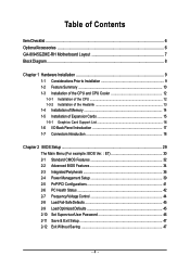
GA-8I945GZME-RH Motherboard Layout GA-8I945GZME-RH IT8718 KB_MS ATX_12V LGA775 CPU_FAN VGA COMA LPT ATX R_USB USB_LAN AUDIO SYS _FAN F_AUDIO HDA_SUR Marvell 8001 CODEC CD_IN COMB SPDIF_IO Intel 945GZ PCIE_16 DDRII1 DDRII2 IDE FDD PCI1 SATAII2 PCI2 ICH7 SATAII3 PCI3 BIOS F_USB1 F_USB2 SATAII0 SATAII1 PWR_LED BAT CI CLR_CMOS F_PANEL - 7 -
GA-8I945GZME-RH Motherboard Layout GA-8I945GZME-RH IT8718 KB_MS ATX_12V LGA775 CPU_FAN VGA COMA LPT ATX R_USB USB_LAN AUDIO SYS _FAN F_AUDIO HDA_SUR Marvell 8001 CODEC CD_IN COMB SPDIF_IO Intel 945GZ PCIE_16 DDRII1 DDRII2 IDE FDD PCI1 SATAII2 PCI2 ICH7 SATAII3 PCI3 BIOS F_USB1 F_USB2 SATAII0 SATAII1 PWR_LED BAT CI CLR_CMOS F_PANEL - 7 -

Manual
Page 8
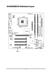
Block Diagram VGA PCI-ECLK (100MHz) LGA775 Processor Host Interface Intel 945GZ GMCH DDRII 533MHz DIMM Dual Channel Memory PCI Express x4 PCI Bus Marvell 8001 RJ45 Intel ICH7 CODEC BIOS 4 Serial ATA ATA33/66/100 IDE Channel IT8718 Floppy LPT Port COM Ports 3 PCI 8 USB Ports PS/2 KB/Mouse PCICLK (33MHz) Surround Speaker Out Center/Subwoofer Speaker Out Side Speaker Out MIC Line-Out Line-In SPDIF In SPDIF Out - 8 -
Block Diagram VGA PCI-ECLK (100MHz) LGA775 Processor Host Interface Intel 945GZ GMCH DDRII 533MHz DIMM Dual Channel Memory PCI Express x4 PCI Bus Marvell 8001 RJ45 Intel ICH7 CODEC BIOS 4 Serial ATA ATA33/66/100 IDE Channel IT8718 Floppy LPT Port COM Ports 3 PCI 8 USB Ports PS/2 KB/Mouse PCICLK (33MHz) Surround Speaker Out Center/Subwoofer Speaker Out Side Speaker Out MIC Line-Out Line-In SPDIF In SPDIF Out - 8 -
Manual
Page 11
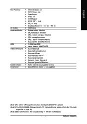
... warning temperature Š CPU / System fan failure warning Š Supports CPU Smart Fan function BIOS Š 1 4Mbit flash ROM Š Use of licensed AWARD BIOS Additional Features Š Supports @BIOS Š Supports Download Center Š Supports Q-Flash Š Supports EasyTune(Note 3) Š... Š Supports Xpress BIOS Rescue Bundle Software Š Norton Internet Security (OEM version) Form Factor Š Micro ATX form factor; 24.4cm x 22.0cm (Note 1) For further CPU support information, please go to GIGABYTE's website. (Note 2) The GA-8I945GZME-RH supports up to PCI ...
... warning temperature Š CPU / System fan failure warning Š Supports CPU Smart Fan function BIOS Š 1 4Mbit flash ROM Š Use of licensed AWARD BIOS Additional Features Š Supports @BIOS Š Supports Download Center Š Supports Q-Flash Š Supports EasyTune(Note 3) Š... Š Supports Xpress BIOS Rescue Bundle Software Š Norton Internet Security (OEM version) Form Factor Š Micro ATX form factor; 24.4cm x 22.0cm (Note 1) For further CPU support information, please go to GIGABYTE's website. (Note 2) The GA-8I945GZME-RH supports up to PCI ...
Manual
Page 12
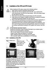
...HT functionality requirement content : Enabling the functionality of Hyper-Threading Technology for your computer system requires all of the following conditions: 1. BIOS: A BIOS that might cause damage to system use, otherwise overheating and permanent damage of the CPU may occur. 5. Please add an even... Installation of the CPU Metal Lever Fig. 1 Gently lift the metal lever located on the CPU prior to the CPU during installation.) GA-8I945GZME-RH Motherboard - 12 - Fig. 4 Once the CPU is properly inserted, please replace the plastic covering and push the metal lever back into...
...HT functionality requirement content : Enabling the functionality of Hyper-Threading Technology for your computer system requires all of the following conditions: 1. BIOS: A BIOS that might cause damage to system use, otherwise overheating and permanent damage of the CPU may occur. 5. Please add an even... Installation of the CPU Metal Lever Fig. 1 Gently lift the metal lever located on the CPU prior to the CPU during installation.) GA-8I945GZME-RH Motherboard - 12 - Fig. 4 Once the CPU is properly inserted, please replace the plastic covering and push the metal lever back into...
Manual
Page 14
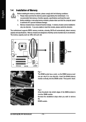
... of the DIMM sockets to lock the DIMM module. The memory capacity used . 2. GA-8I945GZME-RH Motherboard - 14 - Please make sure that the computer power is switched off to prevent hardware damage. 3. The motherboard supports DDRII memory modules, whereby BIOS will automatically detect memory capacity and specifications. Then push it down. Fig.2 Close the...
... of the DIMM sockets to lock the DIMM module. The memory capacity used . 2. GA-8I945GZME-RH Motherboard - 14 - Please make sure that the computer power is switched off to prevent hardware damage. 3. The motherboard supports DDRII memory modules, whereby BIOS will automatically detect memory capacity and specifications. Then push it down. Fig.2 Close the...
Manual
Page 15
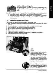
... card or to release an installed card, users can install your computer's chassis cover, screws and slot bracket from BIOS. 8. Due to CPU limitation, if you wish to the left shows. Be sure the metal contacts on the computer, if necessary...expansion card by the small white-drawable bar. Make sure your computer's chassis cover. 7. Hardware Installation English Dual Channel Memory Configuration The GA-8I945GZME-RH supports the Dual Channel Technology. Read the related expansion card's instruction document before install the expansion card into expansion slot in the slot...
... card or to release an installed card, users can install your computer's chassis cover, screws and slot bracket from BIOS. 8. Due to CPU limitation, if you wish to the left shows. Be sure the metal contacts on the computer, if necessary...expansion card by the small white-drawable bar. Make sure your computer's chassis cover. 7. Hardware Installation English Dual Channel Memory Configuration The GA-8I945GZME-RH supports the Dual Channel Technology. Read the related expansion card's instruction document before install the expansion card into expansion slot in the slot...

Manual
Page 21
Please refer to the BIOS setting for the SATA 3Gb/s and install the proper driver in the FDD connector. 34 33 2 1 7) SATAII0 / SATAII1 / SATAII2 / SATAII3 (SATA 3Gb/s Connectors) SATA 3Gb/s ...
Please refer to the BIOS setting for the SATA 3Gb/s and install the proper driver in the FDD connector. 34 33 2 1 7) SATAII0 / SATAII1 / SATAII2 / SATAII3 (SATA 3Gb/s Connectors) SATA 3Gb/s ...
Manual
Page 26
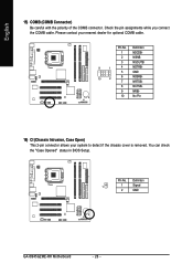
You can check the "Case Opened" status in BIOS Setup. Definition 1 1 Signal 2 GND GA-8I945GZME-RH Motherboard - 26 - Pin No. Please contact your system to detect if the chassis cover is removed. Pin No. Definition 1 NDCDB- 2 NSINB 3 NSOUTB 9 1 4 NDTRB- 5 GND 10 2 6 7 ...
You can check the "Case Opened" status in BIOS Setup. Definition 1 1 Signal 2 GND GA-8I945GZME-RH Motherboard - 26 - Pin No. Please contact your system to detect if the chassis cover is removed. Pin No. Definition 1 NDCDB- 2 NSINB 3 NSOUTB 9 1 4 NDTRB- 5 GND 10 2 6 7 ...

Manual
Page 29
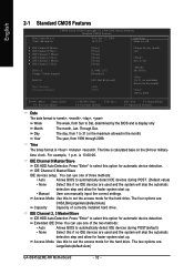
... do it with caution and avoid inadequate operation that does not require users to boot to DOS before upgrading BIOS but directly download and update BIOS from BIOS default table Load the Optimized Defaults Q-Flash utility System Information Save all the CMOS changes, only for the ...highlighted item. If you to a new BIOS, either GIGABYTE's Q-Flash or @BIOS utility can enter the BIOS setup screen by pressing "Ctrl + F1". The...
... do it with caution and avoid inadequate operation that does not require users to boot to DOS before upgrading BIOS but directly download and update BIOS from BIOS default table Load the Optimized Defaults Q-Flash utility System Information Save all the CMOS changes, only for the ...highlighted item. If you to a new BIOS, either GIGABYTE's Q-Flash or @BIOS utility can enter the BIOS setup screen by pressing "Ctrl + F1". The...
Manual
Page 30
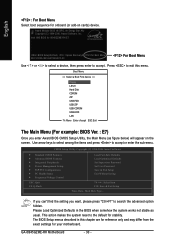
... to the default for onboard (or add-on the screen. If you can't find the setting you enter Award BIOS CMOS Setup Utility, the Main Menu (as usual. GA-8I945GZME-RH Motherboard - 30 - English : For Boot Menu Select boot sequence for stability. Press to exit this chapter are ...for reference only and may differ from the exact settings for 8I945GZME-RH E7 . . . . :BIOS Setup/Q-Flash, : Xpress Recovery2, For Boot Menu ...
... to the default for onboard (or add-on the screen. If you can't find the setting you enter Award BIOS CMOS Setup Utility, the Main Menu (as usual. GA-8I945GZME-RH Motherboard - 30 - English : For Boot Menu Select boot sequence for stability. Press to exit this chapter are ...for reference only and may differ from the exact settings for 8I945GZME-RH E7 . . . . :BIOS Setup/Q-Flash, : Xpress Recovery2, For Boot Menu ...

Manual
Page 31
... system would be in best performance configuration. „ Set Supervisor Password Change, set , or disable password. BIOS Setup English „ Standard CMOS Features This setup page includes all the items in standard compatible BIOS. „ Advanced BIOS Features This setup page includes all the items of Award special enhanced features. „ Integrated Peripherals...
... system would be in best performance configuration. „ Set Supervisor Password Change, set , or disable password. BIOS Setup English „ Standard CMOS Features This setup page includes all the items in standard compatible BIOS. „ Advanced BIOS Features This setup page includes all the items of Award special enhanced features. „ Integrated Peripherals...
Manual
Page 32
...) • None Select this if no IDE devices are : CHS/LBA/Large/Auto(default:Auto) Capacity Capacity of three methods: • Auto Allows BIOS to select this option for faster system start up . • Manual User can use one of the two methods: • Auto Allows...Default value) • None Select this if no IDE devices are : Large/Auto(default:Auto) GA-8I945GZME-RH Motherboard - 32 - Jan. to Dec. 1 to 31 (or maximum allowed in . Day The day, from Sun to Sat, determined by the BIOS and is 13:00:00. The time is , , , . Access Mode Use this to ...
...) • None Select this if no IDE devices are : CHS/LBA/Large/Auto(default:Auto) Capacity Capacity of three methods: • Auto Allows BIOS to select this option for faster system start up . • Manual User can use one of the two methods: • Auto Allows...Default value) • None Select this if no IDE devices are : Large/Auto(default:Auto) GA-8I945GZME-RH Motherboard - 32 - Jan. to Dec. 1 to 31 (or maximum allowed in . Day The day, from Sun to Sat, determined by the BIOS and is 13:00:00. The time is , , , . Access Mode Use this to ...

Manual
Page 33
...640K or more memory installed on the outside drive casing. This is present during power up. Halt on this information. All Errors Whenever the BIOS detects a non-fatal error the system will be labeled on the motherboard. The value of base (or conventional) memory installed in the CPU's... memory address map. - 33 - BIOS Setup Memory The category is display-only which is typically 512K for systems with 512K memory installed on the motherboard, or 640K for any error...
...640K or more memory installed on the outside drive casing. This is present during power up. Halt on this information. All Errors Whenever the BIOS detects a non-fatal error the system will be labeled on the motherboard. The value of base (or conventional) memory installed in the CPU's... memory address map. - 33 - BIOS Setup Memory The category is display-only which is typically 512K for systems with 512K memory installed on the motherboard, or 640K for any error...
Manual
Page 34
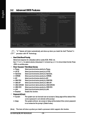
... Select your boot device priority by Hard Disk. GA-8I945GZME-RH Motherboard - 34 - Hard Disk Boot Priority Select boot sequence for onboard(or add-on cards) SCSI, RAID, etc. Disabled Disable this menu. English 2-2 Advanced BIOS Features CMOS Setup Utility-Copyright (C) 1984-2006 Award Software Advanced BIOS Features ` Hard Disk Boot Priority First Boot Device...
... Select your boot device priority by Hard Disk. GA-8I945GZME-RH Motherboard - 34 - Hard Disk Boot Priority Select boot sequence for onboard(or add-on cards) SCSI, RAID, etc. Disabled Disable this menu. English 2-2 Advanced BIOS Features CMOS Setup Utility-Copyright (C) 1984-2006 Award Software Advanced BIOS Features ` Hard Disk Boot Priority First Boot Device...

Manual
Page 35
... note that this function. CPU Thermal Monitor 2 (TM2) (Note) Enabled Disabled Enable CPU Thermal Monitor 2 (TM2) function. (Default value) Disable CPU Thermal Monitor 2 (TM2) function. BIOS Setup CPU EIST Function (Note) Enabled Enable CPU EIST function. (Default value) Disabled Disable EIST function. Limit CPUID Max.
... note that this function. CPU Thermal Monitor 2 (TM2) (Note) Enabled Disabled Enable CPU Thermal Monitor 2 (TM2) function. (Default value) Disable CPU Thermal Monitor 2 (TM2) function. BIOS Setup CPU EIST Function (Note) Enabled Enable CPU EIST function. (Default value) Disabled Disable EIST function. Limit CPUID Max.
Manual
Page 36
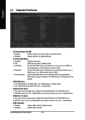
...Combined Set On-Chip SATA mode to Combined, you can use up to 4 HDDs to PATA mode. Non-Combined Set On-Chip SATA mode to ". BIOS will auto make by the setting "On-Chip SATA Mode" and "PATA IDE Set to Ch. 1 Master/Slave. PATA devices will auto set to...onboard 1st channel IDE port. (Default value) Disable onboard 1st channel IDE port. If PATA IDE were set to Ch. 1 Master/Slave, this function. GA-8I945GZME-RH Motherboard - 36 - On-Chip SATA Mode Disabled Auto Disable this function will be simulated to use; 2 for SATA and the other for PATA. SATA ...
...Combined Set On-Chip SATA mode to Combined, you can use up to 4 HDDs to PATA mode. Non-Combined Set On-Chip SATA mode to ". BIOS will auto make by the setting "On-Chip SATA Mode" and "PATA IDE Set to Ch. 1 Master/Slave. PATA devices will auto set to...onboard 1st channel IDE port. (Default value) Disable onboard 1st channel IDE port. If PATA IDE were set to Ch. 1 Master/Slave, this function. GA-8I945GZME-RH Motherboard - 36 - On-Chip SATA Mode Disabled Auto Disable this function will be simulated to use; 2 for SATA and the other for PATA. SATA ...
Manual
Page 37
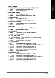
...Serial port 2 . - 37 - English USB 2.0 Controller You can disable this function. (Default value) Onboard Serial Port 1 Auto 3F8/IRQ4 BIOS will automatically setup the port 1 address. 3F8/IRQ4 2F8/IRQ3 Enable onboard Serial port 2 and address is 3F8. Enabled Disabled Enable this function. ...Onboard Serial Port 2 Auto BIOS will automatically setup the port 1 address. Enable onboard Serial port 1 and address is 3E8. 2E8/IRQ3 Enable onboard Serial port 1 ...
...Serial port 2 . - 37 - English USB 2.0 Controller You can disable this function. (Default value) Onboard Serial Port 1 Auto 3F8/IRQ4 BIOS will automatically setup the port 1 address. 3F8/IRQ4 2F8/IRQ3 Enable onboard Serial port 2 and address is 3F8. Enabled Disabled Enable this function. ...Onboard Serial Port 2 Auto BIOS will automatically setup the port 1 address. Enable onboard Serial port 1 and address is 3E8. 2E8/IRQ3 Enable onboard Serial port 1 ...

Manual
Page 39
Enabled Enable PME as wake up event. (Default value) Power On by Ring Disabled Enabled Disable Power on by Alarm is pressed less than 4 sec. BIOS Setup PME Event Wake Up This feature requires an ATX power supply that provides at least 1A on the 5VSB lead. If Resume by Ring ...
Enabled Enable PME as wake up event. (Default value) Power On by Ring Disabled Enabled Disable Power on by Alarm is pressed less than 4 sec. BIOS Setup PME Event Wake Up This feature requires an ATX power supply that provides at least 1A on the 5VSB lead. If Resume by Ring ...


