Manual
Page 1
GA-8I945GZME-RH Intel® Pentium® 4 LGA775 Processor Motherboard User's Manual Rev. 1003 12ME-945GZMER-1003R * The WEEE marking on the product indicates this product must not be disposed of with user's other household waste and must be handed over to a designated collection point for the recycling of waste electrical and electronic equipment!! * The WEEE marking applies only in European Union's member states.
GA-8I945GZME-RH Intel® Pentium® 4 LGA775 Processor Motherboard User's Manual Rev. 1003 12ME-945GZMER-1003R * The WEEE marking on the product indicates this product must not be disposed of with user's other household waste and must be handed over to a designated collection point for the recycling of waste electrical and electronic equipment!! * The WEEE marking applies only in European Union's member states.
Manual
Page 2
Motherboard GA-8I945GZME-RH Jun. 14, 2006 Motherboard GA-8I945GZME-RH Jun. 14, 2006
Motherboard GA-8I945GZME-RH Jun. 14, 2006 Motherboard GA-8I945GZME-RH Jun. 14, 2006
Manual
Page 4
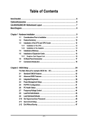
Table of Contents ItemChecklist ...6 OptionalAccessories ...6 GA-8I945GZME-RH Motherboard Layout 7 Block Diagram ...8 Chapter 1 Hardware Installation 9 1-1 Considerations Prior to Installation 9 1-2 Feature Summary 10 1-3 Installation of the CPU and CPU Cooler 12 1-3-1 Installation of the CPU ...
Table of Contents ItemChecklist ...6 OptionalAccessories ...6 GA-8I945GZME-RH Motherboard Layout 7 Block Diagram ...8 Chapter 1 Hardware Installation 9 1-1 Considerations Prior to Installation 9 1-2 Feature Summary 10 1-3 Installation of the CPU and CPU Cooler 12 1-3-1 Installation of the CPU ...
Manual
Page 7
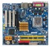
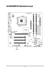
GA-8I945GZME-RH Motherboard Layout GA-8I945GZME-RH IT8718 KB_MS ATX_12V LGA775 CPU_FAN VGA COMA LPT ATX R_USB USB_LAN AUDIO SYS _FAN F_AUDIO HDA_SUR Marvell 8001 CODEC CD_IN COMB SPDIF_IO Intel 945GZ PCIE_16 DDRII1 DDRII2 IDE FDD PCI1 SATAII2 PCI2 ICH7 SATAII3 PCI3 BIOS F_USB1 F_USB2 SATAII0 SATAII1 PWR_LED BAT CI CLR_CMOS F_PANEL - 7 -
GA-8I945GZME-RH Motherboard Layout GA-8I945GZME-RH IT8718 KB_MS ATX_12V LGA775 CPU_FAN VGA COMA LPT ATX R_USB USB_LAN AUDIO SYS _FAN F_AUDIO HDA_SUR Marvell 8001 CODEC CD_IN COMB SPDIF_IO Intel 945GZ PCIE_16 DDRII1 DDRII2 IDE FDD PCI1 SATAII2 PCI2 ICH7 SATAII3 PCI3 BIOS F_USB1 F_USB2 SATAII0 SATAII1 PWR_LED BAT CI CLR_CMOS F_PANEL - 7 -
Manual
Page 9
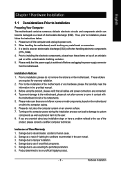
...7. To prevent damage to the motherboard, please do not allow screws ... to Installation Preparing Your Computer The motherboard contains numerous delicate electronic circuits and ... motherboard, avoid touching any hardware, please first carefully read the information in contact with the motherboard circuit... leftover screws or metal components placed on the motherboard or within a electrostatic shielding container. 5. Prior... Turning on the motherboard. Damage due to the use of the motherboard or any metal ...unplugging the power supply connector from the motherboard. Damage due to the user. ...
...7. To prevent damage to the motherboard, please do not allow screws ... to Installation Preparing Your Computer The motherboard contains numerous delicate electronic circuits and ... motherboard, avoid touching any hardware, please first carefully read the information in contact with the motherboard circuit... leftover screws or metal components placed on the motherboard or within a electrostatic shielding container. 5. Prior... Turning on the motherboard. Damage due to the use of the motherboard or any metal ...unplugging the power supply connector from the motherboard. Damage due to the user. ...
Manual
Page 10
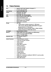
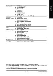
... connector Š 1 COMB connector Š 1 power LED connector Š 2 USB 2.0/1.1 connectors for additional 4 USB 2.0/1.1 ports by cables Š 1 SPDIF In/Out connector Š 1 HDA_SUR connector GA-8I945GZME-RH Motherboard - 10 -
... connector Š 1 COMB connector Š 1 power LED connector Š 2 USB 2.0/1.1 connectors for additional 4 USB 2.0/1.1 ports by cables Š 1 SPDIF In/Out connector Š 1 HDA_SUR connector GA-8I945GZME-RH Motherboard - 10 -
Manual
Page 11
...) Form Factor Š Micro ATX form factor; 24.4cm x 22.0cm (Note 1) For further CPU support information, please go to GIGABYTE's website. (Note 2) The GA-8I945GZME-RH supports up to PCI Express x4 mode. (please refer to the VGA cards support list on page 16) (Note 3) EasyTune functions may vary depending on different motherboards. - 11 -
...) Form Factor Š Micro ATX form factor; 24.4cm x 22.0cm (Note 1) For further CPU support information, please go to GIGABYTE's website. (Note 2) The GA-8I945GZME-RH supports up to PCI Express x4 mode. (please refer to the VGA cards support list on page 16) (Note 3) EasyTune functions may vary depending on different motherboards. - 11 -
Manual
Page 12
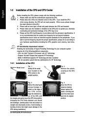
... triangle and gently insert the CPU into position. (Grasping the CPU firmly between the CPU and heatsink. 4. If you wish to the CPU during installation.) GA-8I945GZME-RH Motherboard - 12 - Fig. 4 Once the CPU is installed on the CPU socket to your hardware specifications including the CPU, graphics card, memory, hard drive, etc. Please...
... triangle and gently insert the CPU into position. (Grasping the CPU firmly between the CPU and heatsink. 4. If you wish to the CPU during installation.) GA-8I945GZME-RH Motherboard - 12 - Fig. 4 Once the CPU is installed on the CPU socket to your hardware specifications including the CPU, graphics card, memory, hard drive, etc. Please...
Manual
Page 13
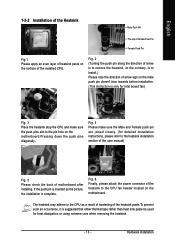
Fig. 4 Please make sure the push pins aim to the pin hole on the motherboard. Hardware Installation The heatsink may adhere to the CPU as the picture, the installation is complete. Fig. 2 (Turning the push pin along the direction of ... the back of arrow sign on the male push pin doesn't face inwards before installation. (This instruction is to install.) Please note the direction of motherboard after installing. Fig. 6 Finally, please attach the power connector of the installed CPU. English 1-3-2 Installation of the Heatsink Male Push Pin The top of Female...
Fig. 4 Please make sure the push pins aim to the pin hole on the motherboard. Hardware Installation The heatsink may adhere to the CPU as the picture, the installation is complete. Fig. 2 (Turning the push pin along the direction of ... the back of arrow sign on the male push pin doesn't face inwards before installation. (This instruction is to install.) Please note the direction of motherboard after installing. Fig. 6 Finally, please attach the power connector of the installed CPU. English 1-3-2 Installation of the Heatsink Male Push Pin The top of Female...
Manual
Page 14
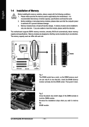
... please switch the direction. A memory module can only fit in one direction. The memory capacity used is supported by the motherboard. Reverse the installation steps when you are designed so that the memory used can be inserted only in only one direction. It...wish to remove the DIMM module. Notch DDRII Fig.1 The DIMM socket has a notch, so the DIMM memory module can be used. 2. GA-8I945GZME-RH Motherboard - 14 - Before installing or removing memory modules, please make sure that they can differ with the following conditions: 1. English 1-4 Installation of ...
... please switch the direction. A memory module can only fit in one direction. The memory capacity used is supported by the motherboard. Reverse the installation steps when you are designed so that the memory used can be inserted only in only one direction. It...wish to remove the DIMM module. Notch DDRII Fig.1 The DIMM socket has a notch, so the DIMM memory module can be used. 2. GA-8I945GZME-RH Motherboard - 14 - Before installing or removing memory modules, please make sure that they can differ with the following conditions: 1. English 1-4 Installation of ...
Manual
Page 15
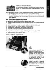
... of the PCI Express x16 slot when you wish to install/ uninstall the VGA card. Power on the card are indeed seated in motherboard. 4. Please align the VGA card to use memory modules of identical brand, size, chips, and speed), you must install them into...out the small whitedrawable bar at the end of the expansion card. 6. Remove your computer's chassis cover. 7. English Dual Channel Memory Configuration The GA-8I945GZME-RH supports the Dual Channel Technology. Due to CPU limitation, if you try to operate the Dual Channel Technology, follow the guidelines below : 1. ...
... of the PCI Express x16 slot when you wish to install/ uninstall the VGA card. Power on the card are indeed seated in motherboard. 4. Please align the VGA card to use memory modules of identical brand, size, chips, and speed), you must install them into...out the small whitedrawable bar at the end of the expansion card. 6. Remove your computer's chassis cover. 7. English Dual Channel Memory Configuration The GA-8I945GZME-RH supports the Dual Channel Technology. Due to CPU limitation, if you try to operate the Dual Channel Technology, follow the guidelines below : 1. ...
Manual
Page 16
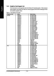
... Nvidia ATi Maker Gigabyte Gigabyte Gigabyte Gigabyte Gigabyte Gigabyte Gigabyte Gigabyte Gigabyte Gigabyte Gigabyte Gigabyte Gigabyte Gigabyte Gigabyte Gigabyte Gigabyte Gigabyte Gigabyte Gigabyte Nvidia Nvidia ASUS MSI WinFast Gigabyte Gigabyte Gigabyte Gigabyte Gigabyte Gigabyte Gigabyte Gigabyte Gigabyte Gigabyte Gigabyte Gigabyte Gigabyte Gigabyte Gigabyte Gigabyte ASUS ASUS MSI ...GV-RX55128D GV-RX85T256V-B GV-RC850T256D-B GV-RX13P256D-RH GV-RX16P256D-RH GV-RX18L256V-B GV-RX18T512V-B AX800XT AX700PRO RX600 XT-TD128 GA-8I945GZME-RH Motherboard - 16 - English 1-5-1 Graphics Card Support ...
... Nvidia ATi Maker Gigabyte Gigabyte Gigabyte Gigabyte Gigabyte Gigabyte Gigabyte Gigabyte Gigabyte Gigabyte Gigabyte Gigabyte Gigabyte Gigabyte Gigabyte Gigabyte Gigabyte Gigabyte Gigabyte Gigabyte Nvidia Nvidia ASUS MSI WinFast Gigabyte Gigabyte Gigabyte Gigabyte Gigabyte Gigabyte Gigabyte Gigabyte Gigabyte Gigabyte Gigabyte Gigabyte Gigabyte Gigabyte Gigabyte Gigabyte ASUS ASUS MSI ...GV-RX55128D GV-RX85T256V-B GV-RC850T256D-B GV-RX13P256D-RH GV-RX16P256D-RH GV-RX18L256V-B GV-RX18T512V-B AX800XT AX700PRO RX600 XT-TD128 GA-8I945GZME-RH Motherboard - 16 - English 1-5-1 Graphics Card Support ...
Manual
Page 18
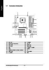
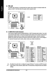
English 1-7 Connectors Introduction 1 3 2 4 5 6 9 13 7 18 16 11 10 12 15 14 8 17 1) ATX_12V 10) F_PANEL 2) ATX (Power Connector) 11) CD_IN 3) CPU_FAN 12) SPDIF_IO 4) SYS_FAN 13) HDA_SUR 5) IDE 14) F_USB1 / F_USB2 6) FDD 15) COMB 7) SATAII0 / SATAII1 /S ATAII2 / SATAII3 16) C I 8) PWR_LED 17) CLR_CMOS 9) F_AUDIO 18) BAT GA-8I945GZME-RH Motherboard - 18 -
English 1-7 Connectors Introduction 1 3 2 4 5 6 9 13 7 18 16 11 10 12 15 14 8 17 1) ATX_12V 10) F_PANEL 2) ATX (Power Connector) 11) CD_IN 3) CPU_FAN 12) SPDIF_IO 4) SYS_FAN 13) HDA_SUR 5) IDE 14) F_USB1 / F_USB2 6) FDD 15) COMB 7) SATAII0 / SATAII1 /S ATAII2 / SATAII3 16) C I 8) PWR_LED 17) CLR_CMOS 9) F_AUDIO 18) BAT GA-8I945GZME-RH Motherboard - 18 -
Manual
Page 19
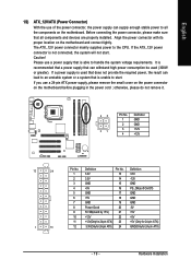
...pin ATX power supply, please remove the small cover on the power connector on the motherboard and connect tightly. Before connecting the power connector, please make sure that all the components on the motherboard. The ATX_12V power connector mainly supplies power to the CPU. If the ATX_12V power connector...+5V (Only for 24-pin ATX) GND(Only for 24-pin ATX) - 19 - Align the power connector with its proper location on the motherboard before plugging in the power cord ; English 1/2) ATX_12V/ATX (Power Connector) With the use of the power connector, the power supply can withstand high...
...pin ATX power supply, please remove the small cover on the power connector on the motherboard and connect tightly. Before connecting the power connector, please make sure that all the components on the motherboard. The ATX_12V power connector mainly supplies power to the CPU. If the ATX_12V power connector...+5V (Only for 24-pin ATX) GND(Only for 24-pin ATX) - 19 - Align the power connector with its proper location on the motherboard before plugging in the power cord ; English 1/2) ATX_12V/ATX (Power Connector) With the use of the power connector, the power supply can withstand high...
Manual
Page 20
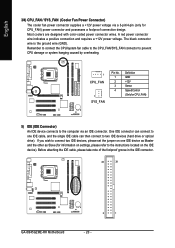
... to the computer via an IDE connector. Before attaching the IDE cable, please take note of the foolproof groove in the IDE connector. 40 39 GA-8I945GZME-RH Motherboard 2 1 - 20 - If you wish to connect two IDE devices, please set the jumper on one IDE cable, and the single IDE cable can then connect...
... to the computer via an IDE connector. Before attaching the IDE cable, please take note of the foolproof groove in the IDE connector. 40 39 GA-8I945GZME-RH Motherboard 2 1 - 20 - If you wish to connect two IDE devices, please set the jumper on one IDE cable, and the single IDE cable can then connect...
Manual
Page 22
If you connect the front panel audio module. GA-8I945GZME-RH Motherboard - 22 - Check the pin assignments carefully while you wish to use the front audio function, connect the front panel audio module to this connector, please ...
If you connect the front panel audio module. GA-8I945GZME-RH Motherboard - 22 - Check the pin assignments carefully while you wish to use the front audio function, connect the front panel audio module to this connector, please ...
Manual
Page 24
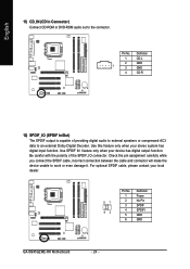
... has digital input function. For optional SPDIF cable, please contact your local dealer. 51 62 Pin No. 1 2 3 4 5 6 Definition Power No Pin SPDIF SPDIFI GND GND GA-8I945GZME-RH Motherboard - 24 - Check the pin assignment carefully while you connect the SPDIF cable, incorrect connection between the cable and connector will make the device unable to...
... has digital input function. For optional SPDIF cable, please contact your local dealer. 51 62 Pin No. 1 2 3 4 5 6 Definition Power No Pin SPDIF SPDIFI GND GND GA-8I945GZME-RH Motherboard - 24 - Check the pin assignment carefully while you connect the SPDIF cable, incorrect connection between the cable and connector will make the device unable to...
Manual
Page 26
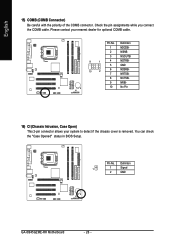
Definition 1 1 Signal 2 GND GA-8I945GZME-RH Motherboard - 26 - Pin No. Pin No. Please contact your system to detect if the chassis cover is removed. You can check the "Case Opened" status in ...
Definition 1 1 Signal 2 GND GA-8I945GZME-RH Motherboard - 26 - Pin No. Pin No. Please contact your system to detect if the chassis cover is removed. You can check the "Case Opened" status in ...

Manual
Page 29
... CMOS SRAM. Quit and not save changes into CMOS Status Page Setup Menu and Option Page Setup Menu - Because BIOS flashing is turned on the motherboard supplies the necessary power to the CMOS SETUP screen. To exit the Help Window press . English Chapter 2 BIOS Setup BIOS (Basic Input and Output...off, the battery on , press the button during the BIOS POST (Power-On Self Test) will take you wish to upgrade to a new BIOS, either GIGABYTE's Q-Flash or @BIOS utility can enter the BIOS setup screen by pressing "Ctrl + F1". BIOS Setup You can be used. The CMOS SETUP saves ...
... CMOS SRAM. Quit and not save changes into CMOS Status Page Setup Menu and Option Page Setup Menu - Because BIOS flashing is turned on the motherboard supplies the necessary power to the CMOS SETUP screen. To exit the Help Window press . English Chapter 2 BIOS Setup BIOS (Basic Input and Output...off, the battery on , press the button during the BIOS POST (Power-On Self Test) will take you wish to upgrade to a new BIOS, either GIGABYTE's Q-Flash or @BIOS utility can enter the BIOS setup screen by pressing "Ctrl + F1". BIOS Setup You can be used. The CMOS SETUP saves ...
Manual
Page 30
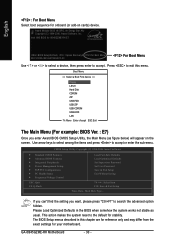
.... Use arrow keys to select among the items and press to accept . This action makes the system reset to the default for your motherboard. Boot Menu == Select a Boot First device == Floppy LS120 Hard Disk CDROM ZIP USB-FDD USB-ZIP USB-CDROM USB-HDD LAN KL... Type... Intel I945 BIOS for 8I945GZME-RH E7 . . . . :BIOS Setup/Q-Flash, : Xpress Recovery2, For Boot Menu 06/01/2006-I945-6A79HG0VC-00 For Boot Menu Use < > or < > to select a device, then press enter to accept or enter the sub-menu. Press to search the advanced option hidden. GA-8I945GZME-RH Motherboard - 30 -
.... Use arrow keys to select among the items and press to accept . This action makes the system reset to the default for your motherboard. Boot Menu == Select a Boot First device == Floppy LS120 Hard Disk CDROM ZIP USB-FDD USB-ZIP USB-CDROM USB-HDD LAN KL... Type... Intel I945 BIOS for 8I945GZME-RH E7 . . . . :BIOS Setup/Q-Flash, : Xpress Recovery2, For Boot Menu 06/01/2006-I945-6A79HG0VC-00 For Boot Menu Use < > or < > to select a device, then press enter to accept or enter the sub-menu. Press to search the advanced option hidden. GA-8I945GZME-RH Motherboard - 30 -


