Manual
Page 4
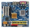
...the CPU 12 1-3-2 Installation of the Heatsink 13 1-4 Installation of Memory 14 1-5 Installation of Expansion Cards 15 1-5-1 Graphics Card Support List 16 1-6 I/O Back Panel Introduction 17 1-7 Connectors Introduction 18 Chapter 2 BIOS Setup 29 The Main Menu (For example: BIOS Ver. : E7 30 2-1 Standard CMOS Features 32 2-2 Advanced BIOS Features 34 2-3 IntegratedPeripherals 36 2-4 Power Management Setup 39 2-5 PnP/PCI Configurations 41 2-6 PC Health Status 42 2-7 Frequency/Voltage Control 44 2-8 Load Fail-Safe Defaults 45 2-9 Load Optimized Defaults 45 2-10 Set Supervisor/User...
...the CPU 12 1-3-2 Installation of the Heatsink 13 1-4 Installation of Memory 14 1-5 Installation of Expansion Cards 15 1-5-1 Graphics Card Support List 16 1-6 I/O Back Panel Introduction 17 1-7 Connectors Introduction 18 Chapter 2 BIOS Setup 29 The Main Menu (For example: BIOS Ver. : E7 30 2-1 Standard CMOS Features 32 2-2 Advanced BIOS Features 34 2-3 IntegratedPeripherals 36 2-4 Power Management Setup 39 2-5 PnP/PCI Configurations 41 2-6 PC Health Status 42 2-7 Frequency/Voltage Control 44 2-8 Load Fail-Safe Defaults 45 2-9 Load Optimized Defaults 45 2-10 Set Supervisor/User...
Manual
Page 10
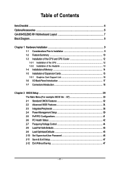
...PCI Express x16 slot(Note 2) Š 3 PCI slots Internal Connectors Š 1 24-pin ATX power connector Š 1 4-pin ATX 12V power connector Š 1 floppy connector Š 1 IDE connector Š 4 SATA 3Gb/s connectors Š 1 CPU fan connector Š 1 system fan connector Š 1 front panel connector Š 1 front audio connector Š 1 CD In connector Š 1 COMB connector Š 1 power LED connector Š 2 USB 2.0/1.1 connectors for additional 4 USB 2.0/1.1 ports by cables Š 1 SPDIF In/Out connector Š 1 HDA_SUR connector GA-8I945GZME-RH Motherboard...
...PCI Express x16 slot(Note 2) Š 3 PCI slots Internal Connectors Š 1 24-pin ATX power connector Š 1 4-pin ATX 12V power connector Š 1 floppy connector Š 1 IDE connector Š 4 SATA 3Gb/s connectors Š 1 CPU fan connector Š 1 system fan connector Š 1 front panel connector Š 1 front audio connector Š 1 CD In connector Š 1 COMB connector Š 1 power LED connector Š 2 USB 2.0/1.1 connectors for additional 4 USB 2.0/1.1 ports by cables Š 1 SPDIF In/Out connector Š 1 HDA_SUR connector GA-8I945GZME-RH Motherboard...
Manual
Page 11
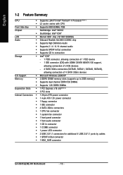
... 1 PS/2 keyboard port Š 1 PS/2 mouse port Š 1 parallel port Š 1 VGA port Š 1 COMA port Š 4 USB 2.0/1.1 ports Š 1 RJ-45 ports Š 3 audio jacks (Line In / Line Out / MIC In) I/O Control Š IT8718 chip Hardware Monitor Š System voltage detection Š CPU temperature detection Š CPU / System fan speed detection Š CPU warning temperature Š CPU / System fan failure warning Š Supports CPU Smart Fan function BIOS Š 1 4Mbit flash ROM Š Use of licensed AWARD BIOS Additional Features Š Supports @BIOS Š...
... 1 PS/2 keyboard port Š 1 PS/2 mouse port Š 1 parallel port Š 1 VGA port Š 1 COMA port Š 4 USB 2.0/1.1 ports Š 1 RJ-45 ports Š 3 audio jacks (Line In / Line Out / MIC In) I/O Control Š IT8718 chip Hardware Monitor Š System voltage detection Š CPU temperature detection Š CPU / System fan speed detection Š CPU warning temperature Š CPU / System fan failure warning Š Supports CPU Smart Fan function BIOS Š 1 4Mbit flash ROM Š Use of licensed AWARD BIOS Additional Features Š Supports @BIOS Š...
Manual
Page 15
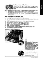
... expansion card's instruction document before install the expansion card into expansion slot in the slot. 5. Replace your VGA card is locked by following the steps outlined below : 1. Hardware Installation English Dual Channel Memory Configuration The GA-8I945GZME-RH supports the Dual Channel Technology. Install related driver from the computer. 3. Please align the VGA card to secure the slot bracket of Expansion Cards You can also press the latch on the card are indeed seated in motherboard. 4. To enable Dual Channel mode with two memory...
... expansion card's instruction document before install the expansion card into expansion slot in the slot. 5. Replace your VGA card is locked by following the steps outlined below : 1. Hardware Installation English Dual Channel Memory Configuration The GA-8I945GZME-RH supports the Dual Channel Technology. Install related driver from the computer. 3. Please align the VGA card to secure the slot bracket of Expansion Cards You can also press the latch on the card are indeed seated in motherboard. 4. To enable Dual Channel mode with two memory...
Manual
Page 16
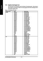
When using an add-on graphics card, please first delete the onboard graphics driver before installing the driver for the add-on graphics card.) Figure 1. PCI Express x16 Cards Graphics Chip Nvidia ATi Maker Gigabyte Gigabyte Gigabyte Gigabyte Gigabyte Gigabyte Gigabyte Gigabyte Gigabyte Gigabyte Gigabyte Gigabyte Gigabyte Gigabyte Gigabyte Gigabyte Gigabyte Gigabyte Gigabyte Gigabyte Nvidia Nvidia ASUS MSI WinFast Gigabyte Gigabyte Gigabyte Gigabyte Gigabyte Gigabyte Gigabyte Gigabyte Gigabyte Gigabyte Gigabyte Gigabyte Gigabyte Gigabyte Gigabyte Gigabyte ASUS ASUS MSI Model Name GV-...
When using an add-on graphics card, please first delete the onboard graphics driver before installing the driver for the add-on graphics card.) Figure 1. PCI Express x16 Cards Graphics Chip Nvidia ATi Maker Gigabyte Gigabyte Gigabyte Gigabyte Gigabyte Gigabyte Gigabyte Gigabyte Gigabyte Gigabyte Gigabyte Gigabyte Gigabyte Gigabyte Gigabyte Gigabyte Gigabyte Gigabyte Gigabyte Gigabyte Nvidia Nvidia ASUS MSI WinFast Gigabyte Gigabyte Gigabyte Gigabyte Gigabyte Gigabyte Gigabyte Gigabyte Gigabyte Gigabyte Gigabyte Gigabyte Gigabyte Gigabyte Gigabyte Gigabyte ASUS ASUS MSI Model Name GV-...
Manual
Page 20
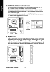
... Sense Speed Control (Only for CPU_FAN) 5) IDE (IDE Connector) An IDE device connects to the computer via a 3-pin/4-pin (only for information on settings, please refer to two IDE devices (hard drive or optical drive). English 3/4) CPU_FAN / SYS_FAN (Cooler Fan Power Connector) The cooler fan power connector supplies a +12V power voltage via an IDE connector. Before attaching the IDE cable, please take note of the foolproof groove in the IDE connector. 40 39 GA-8I945GZME-RH Motherboard 2 1 - 20 - One IDE connector can connect to one IDE cable, and the single IDE cable...
... Sense Speed Control (Only for CPU_FAN) 5) IDE (IDE Connector) An IDE device connects to the computer via a 3-pin/4-pin (only for information on settings, please refer to two IDE devices (hard drive or optical drive). English 3/4) CPU_FAN / SYS_FAN (Cooler Fan Power Connector) The cooler fan power connector supplies a +12V power voltage via an IDE connector. Before attaching the IDE cable, please take note of the foolproof groove in the IDE connector. 40 39 GA-8I945GZME-RH Motherboard 2 1 - 20 - One IDE connector can connect to one IDE cable, and the single IDE cable...

Manual
Page 21
.../s Connectors) SATA 3Gb/s can provide up to work properly. 1 SATAII2 7 1 SATAII0 7 7 SATAII3 1 7 SATAII1 Pin No. 1 2 3 4 5 6 7 Definition GND TXP TXN GND RXN RXP GND 1 - 21 - Hardware Installation Before attaching the FDD cable, please take note of the foolproof groove in order to 300MB/s transfer rate. The types of the cable connects to the FDD drive. English 6) FDD (FDD Connector) The FDD connector is used...
.../s Connectors) SATA 3Gb/s can provide up to work properly. 1 SATAII2 7 1 SATAII0 7 7 SATAII3 1 7 SATAII1 Pin No. 1 2 3 4 5 6 7 Definition GND TXP TXN GND RXN RXP GND 1 - 21 - Hardware Installation Before attaching the FDD cable, please take note of the foolproof groove in order to 300MB/s transfer rate. The types of the cable connects to the FDD drive. English 6) FDD (FDD Connector) The FDD connector is used...
Manual
Page 22
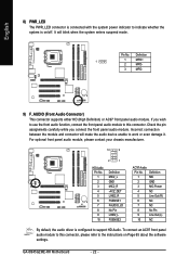
... system enters suspend mode. Definition 1 MIC 2 GND 3 MIC Power 4 NC 5 Line Out (R) 6 NC 7 NC 8 No Pin 9 Line Out (L) 10 NC By default, the audio driver is on Page 65 about the software settings. Pin No. It will make the audio device unable to work or even damage it. GA-8I945GZME-RH Motherboard - 22 - If you connect the front panel audio module. Definition 1 1 MPD+ 2 MPD- 3 MPD- 9) F_AUDIO (Front Audio Connector) This connector supports either HD (High...
... system enters suspend mode. Definition 1 MIC 2 GND 3 MIC Power 4 NC 5 Line Out (R) 6 NC 7 NC 8 No Pin 9 Line Out (L) 10 NC By default, the audio driver is on Page 65 about the software settings. Pin No. It will make the audio device unable to work or even damage it. GA-8I945GZME-RH Motherboard - 22 - If you connect the front panel audio module. Definition 1 1 MPD+ 2 MPD- 3 MPD- 9) F_AUDIO (Front Audio Connector) This connector supports either HD (High...

Manual
Page 23
... 10) F_PANEL (Front Panel Jumper) Please connect the power LED, PC speaker, reset switch and power switch etc of your chassis front panel to the F_PANEL connector according to the pin assignment below. Message LED/ Power/ Sleep LED Speaker Connector Power Switch MSG+ MSG- RESRES+ NC HD (IDE Hard Disk Active LED) SPEAK (Speaker Connector) RES (Reset Switch) PW (Power Switch) MSG (Message LED/Power/Sleep LED) NC Reset Switch IDE Hard Disk Active LED Pin 1: LED anode(+) Pin 2: LED cathode(-) Pin 1: Power Pin 2- Pin 3: NC Pin 4: Data(-) Open: Normal Close: Reset Hardware System Open...
... 10) F_PANEL (Front Panel Jumper) Please connect the power LED, PC speaker, reset switch and power switch etc of your chassis front panel to the F_PANEL connector according to the pin assignment below. Message LED/ Power/ Sleep LED Speaker Connector Power Switch MSG+ MSG- RESRES+ NC HD (IDE Hard Disk Active LED) SPEAK (Speaker Connector) RES (Reset Switch) PW (Power Switch) MSG (Message LED/Power/Sleep LED) NC Reset Switch IDE Hard Disk Active LED Pin 1: LED anode(+) Pin 2: LED cathode(-) Pin 1: Power Pin 2- Pin 3: NC Pin 4: Data(-) Open: Normal Close: Reset Hardware System Open...
Manual
Page 30
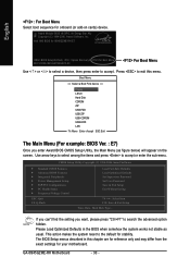
... Menu == Select a Boot First device == Floppy LS120 Hard Disk CDROM ZIP USB-FDD USB-ZIP USB-CDROM USB-HDD LAN KL:Move Enter :Accept ESC:Exit The Main Menu (For example: BIOS Ver. : E7) Once you want, please press "Ctrl+F1" to accept or enter the sub-menu. CMOS Setup Utility-Copyright (C) 1984-2006 Award Software ` Standard CMOS Features ` Advanced BIOS Features ` Integrated Peripherals ` Power Management Setup ` PnP/PCI Configurations ` PC Health Status ` Frequency/Voltage Control ESC: Quit F8: Q-Flash Load Fail-Safe Defaults Load Optimized Defaults Set Supervisor Password Set User...
... Menu == Select a Boot First device == Floppy LS120 Hard Disk CDROM ZIP USB-FDD USB-ZIP USB-CDROM USB-HDD LAN KL:Move Enter :Accept ESC:Exit The Main Menu (For example: BIOS Ver. : E7) Once you want, please press "Ctrl+F1" to accept or enter the sub-menu. CMOS Setup Utility-Copyright (C) 1984-2006 Award Software ` Standard CMOS Features ` Advanced BIOS Features ` Integrated Peripherals ` Power Management Setup ` PnP/PCI Configurations ` PC Health Status ` Frequency/Voltage Control ESC: Quit F8: Q-Flash Load Fail-Safe Defaults Load Optimized Defaults Set Supervisor Password Set User...
Manual
Page 32
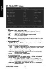
... this option for automatic device detection. IDE Channel 2, 3 Master/Slave IDE HDD Auto-Detection Press "Enter" to select this option for automatic device detection. English 2-1 Standard CMOS Features Date (mm:dd:yy) Time (hh:mm:ss) CMOS Setup Utility-Copyright (C) 1984-2006 Award Software Standard CMOS Features Wed, Apr 12 2006 14:31:24 Item Help Menu Level` ` IDE Channel 0 Master ` IDE Channel 0 Slave ` IDE Channel 2 Master ` IDE Channel 2 Slave ` IDE Channel 3 Master ` IDE Channel 3 Slave Drive A Floppy 3 Mode Support Halt On Base Memory Extended Memory...
... this option for automatic device detection. IDE Channel 2, 3 Master/Slave IDE HDD Auto-Detection Press "Enter" to select this option for automatic device detection. English 2-1 Standard CMOS Features Date (mm:dd:yy) Time (hh:mm:ss) CMOS Setup Utility-Copyright (C) 1984-2006 Award Software Standard CMOS Features Wed, Apr 12 2006 14:31:24 Item Help Menu Level` ` IDE Channel 0 Master ` IDE Channel 0 Slave ` IDE Channel 2 Master ` IDE Channel 2 Slave ` IDE Channel 3 Master ` IDE Channel 3 Slave Drive A Floppy 3 Mode Support Halt On Base Memory Extended Memory...
Manual
Page 34
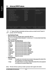
.... GA-8I945GZME-RH Motherboard - 34 - Setup The system will be denied if the correct password is not entered at the prompt. English 2-2 Advanced BIOS Features CMOS Setup Utility-Copyright (C) 1984-2006 Award Software Advanced BIOS Features ` Hard Disk Boot Priority First Boot Device Second Boot Device Third Boot Device Password Check # CPU Hyper-Threading Limit CPUID Max. to exit this function. Use < > or < > to select a device, then press to move it down the list. USB-HDD Select your boot device priority by USB-HDD. Disabled Disable this menu.
.... GA-8I945GZME-RH Motherboard - 34 - Setup The system will be denied if the correct password is not entered at the prompt. English 2-2 Advanced BIOS Features CMOS Setup Utility-Copyright (C) 1984-2006 Award Software Advanced BIOS Features ` Hard Disk Boot Priority First Boot Device Second Boot Device Third Boot Device Password Check # CPU Hyper-Threading Limit CPUID Max. to exit this function. Use < > or < > to select a device, then press to move it down the list. USB-HDD Select your boot device priority by USB-HDD. Disabled Disable this menu.

Manual
Page 43
...to Voltage when you use a CPU fan with 3-pin or 4-pin power cables. However, some 4-pin CPU fan power cables are not designed following Intel 4-Wire fans PWM control specifications. Auto BIOS autodetects the type of CPU fan you installed and sets the optimal CPU Smart FAN control mode for CPU fans with a 3-pin fan power cable. BIOS Setup Enabled When this function. English CPU Smart FAN Control Disabled Disable this function is enabled. Users can be used for it. (Default Value) Voltage Set to PWM when you use a CPU fan with Easy Tune based on CPU temperature...
...to Voltage when you use a CPU fan with 3-pin or 4-pin power cables. However, some 4-pin CPU fan power cables are not designed following Intel 4-Wire fans PWM control specifications. Auto BIOS autodetects the type of CPU fan you installed and sets the optimal CPU Smart FAN control mode for CPU fans with a 3-pin fan power cable. BIOS Setup Enabled When this function. English CPU Smart FAN Control Disabled Disable this function is enabled. Users can be used for it. (Default Value) Voltage Set to PWM when you use a CPU fan with Easy Tune based on CPU temperature...

Manual
Page 46
...password. GA-8I945GZME-RH Motherboard - 46 - Type the password, up to specify two separate passwords: SUPERVISOR PASSWORD and a USER PASSWORD. Type the password again and press . To disable password, just press when you are prompted to enter password. English 2-10 Set Supervisor/User Password CMOS Setup Utility-Copyright (C) 1984-2006 Award Software ` Standard CMOS Features ` Advanced BIOS Features ` Integrated Peripherals ` Power Management Setup ` PnP/PCI ConfiguratioEnsnter Password: ` PC Health Status ` Frequency/Voltage Control Load Fail-Safe Defaults Load Optimized Defaults...
...password. GA-8I945GZME-RH Motherboard - 46 - Type the password, up to specify two separate passwords: SUPERVISOR PASSWORD and a USER PASSWORD. Type the password again and press . To disable password, just press when you are prompted to enter password. English 2-10 Set Supervisor/User Password CMOS Setup Utility-Copyright (C) 1984-2006 Award Software ` Standard CMOS Features ` Advanced BIOS Features ` Integrated Peripherals ` Power Management Setup ` PnP/PCI ConfiguratioEnsnter Password: ` PC Health Status ` Frequency/Voltage Control Load Fail-Safe Defaults Load Optimized Defaults...
Manual
Page 49
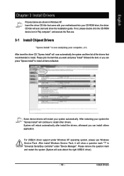
... not, please double click the CD-ROM device icon in Windows XP. After restarting your system the "Xpress Install" will restart your CD-ROM drive, the driver CD-title will auto start and show a question mark "?" in "Universal Serial Bus controller" under Windows XP operating system, please use Windows Service Pack. Some device drivers will continue to install. Install Drivers For USB2.0 driver support under "Device Manager". Please remove the question mark and restart the...
... not, please double click the CD-ROM device icon in Windows XP. After restarting your system the "Xpress Install" will restart your CD-ROM drive, the driver CD-title will auto start and show a question mark "?" in "Universal Serial Bus controller" under Windows XP operating system, please use Windows Service Pack. Some device drivers will continue to install. Install Drivers For USB2.0 driver support under "Device Manager". Please remove the question mark and restart the...

Manual
Page 54
... Recovery2 later, you have already entered Xpress Recovery2 by simply pressing the key during system bootup to startup XpressRecovery2..... GA-8I945GZME-RH Motherboard - 54 - Save the settings and exit the BIOS Setup. Press any key to enter Xpress Recovery2 without the CD-ROM. Boot from CD/DVD: Press any key to back up data on hard disks on . . . Supporting Microsoft operating systems including Windows XP/2000/NT/98/Me...
... Recovery2 later, you have already entered Xpress Recovery2 by simply pressing the key during system bootup to startup XpressRecovery2..... GA-8I945GZME-RH Motherboard - 54 - Save the settings and exit the BIOS Setup. Press any key to enter Xpress Recovery2 without the CD-ROM. Boot from CD/DVD: Press any key to back up data on hard disks on . . . Supporting Microsoft operating systems including Windows XP/2000/NT/98/Me...

Manual
Page 57
... English Entering the Q-FlashTM utility: Step1: To use Q-Flash utility, you must press Del in the boot screen to enter BIOS menu. CMOS Setup Utility-Copyright (C) 1984-2004 Award Software Standard CMOS Features Advanced BIOS Features Integrated Peripherals Power Management Setup PnP/PCI Configurations PC Health Status MB Intelligent Tweaker(M.I.T.) ESC: Quit F8: Dual BIOS/Q-Flash Select Language Load Fail-Safe Defaults Load Optimized Defaults Set Supervisor Password Set User Password Save & Exit Setup Exit Without Saving F3: Change Language F10: Save & Exit Setup Time, Date, Hard Disk Type...
... English Entering the Q-FlashTM utility: Step1: To use Q-Flash utility, you must press Del in the boot screen to enter BIOS menu. CMOS Setup Utility-Copyright (C) 1984-2004 Award Software Standard CMOS Features Advanced BIOS Features Integrated Peripherals Power Management Setup PnP/PCI Configurations PC Health Status MB Intelligent Tweaker(M.I.T.) ESC: Quit F8: Dual BIOS/Q-Flash Select Language Load Fail-Safe Defaults Load Optimized Defaults Set Supervisor Password Set User Password Save & Exit Setup Exit Without Saving F3: Change Language F10: Save & Exit Setup Time, Date, Hard Disk Type...

Manual
Page 59
... Disable Boot From Main Bios !A! Press Esc and then Y button to flash the backup BIOS, too. 5. Please do not take out the floppy disk when it will begin to update BIOS. Award Modular BIOS v6.00PG, An Energy Star Ally Copyright (C) 1984-2003, Award Software, Inc. Halt On Error Disable [EnCtoepry] tMoacionnRtiOnuMreDoarta[EtoscB]atcokuapbort... Load Default Settings Save Settings to CMOS Q-Flash Utility Load Main BIOS from Floppy Load Backup BIOS from Floppy Save Main BIOS to Floppy Save Backup BIOS to Floppy Enter : Run :Move ESC:Reset...
... Disable Boot From Main Bios !A! Press Esc and then Y button to flash the backup BIOS, too. 5. Please do not take out the floppy disk when it will begin to update BIOS. Award Modular BIOS v6.00PG, An Energy Star Ally Copyright (C) 1984-2003, Award Software, Inc. Halt On Error Disable [EnCtoepry] tMoacionnRtiOnuMreDoarta[EtoscB]atcokuapbort... Load Default Settings Save Settings to CMOS Q-Flash Utility Load Main BIOS from Floppy Load Backup BIOS from Floppy Save Main BIOS to Floppy Save Backup BIOS to Floppy Enter : Run :Move ESC:Reset...

Manual
Page 60
... Tweaker(M.I.T.) ESC: Quit F8: Q-Flash Top Performance Load Fail-Safe Defaults Load Optimized Defaults Set Supervisor Password Set User Password Save & Exit Setup Exit Without Saving F3: Change Language F10: Save & Exit Setup Time, Date, Hard Disk Type... System will reboot after BIOS has been upgraded. Normally the system redetects all devices after system reboots. Press Del to load BIOS Optimized Defaults. Part Two: Updating BIOS with Q-FlashTM Utility on your keyboard to save the settings to update BIOS using the Q-FlashTM...
... Tweaker(M.I.T.) ESC: Quit F8: Q-Flash Top Performance Load Fail-Safe Defaults Load Optimized Defaults Set Supervisor Password Set User Password Save & Exit Setup Exit Without Saving F3: Change Language F10: Save & Exit Setup Time, Date, Hard Disk Type... System will reboot after BIOS has been upgraded. Normally the system redetects all devices after system reboots. Press Del to load BIOS Optimized Defaults. Part Two: Updating BIOS with Q-FlashTM Utility on your keyboard to save the settings to update BIOS using the Q-FlashTM...

Manual
Page 71
...take off power. 2. AWARD BIOS Beep Codes 1 short: System boots successfully 2 short: CMOS setting error 1 long 1 short: DRAM or M/B error 1 long 2 short: Monitor or display card error 1 long 3 short: Keyboard error 1 long 9 short: BIOS ROM error Continuous long beeps: DRAM error Continuous short beeps: Power error - 71 - English 4-2 Troubleshooting Below is equipped with power/amplifier and try again later. Please press Ctrl and F1 keys after turning up . Re-insert the battery to MB again and turn on to case. Appendix Answer: Some advanced options are using is a collection...
...take off power. 2. AWARD BIOS Beep Codes 1 short: System boots successfully 2 short: CMOS setting error 1 long 1 short: DRAM or M/B error 1 long 2 short: Monitor or display card error 1 long 3 short: Keyboard error 1 long 9 short: BIOS ROM error Continuous long beeps: DRAM error Continuous short beeps: Power error - 71 - English 4-2 Troubleshooting Below is equipped with power/amplifier and try again later. Please press Ctrl and F1 keys after turning up . Re-insert the battery to MB again and turn on to case. Appendix Answer: Some advanced options are using is a collection...


