Manual
Page 1
GA-8I915ME Series Intel® Pentium® 4 LGA775 Processor Motherboard User's Manual Rev. 1003 12ME-I915MES-1003 * The WEEE marking on the product indicates this product must not be disposed of with user's other household waste and must be handed over to a designated collection point for the recycling of waste electrical and electronic equipment!! * The WEEE marking applies only in European Union's member states.
GA-8I915ME Series Intel® Pentium® 4 LGA775 Processor Motherboard User's Manual Rev. 1003 12ME-I915MES-1003 * The WEEE marking on the product indicates this product must not be disposed of with user's other household waste and must be handed over to a designated collection point for the recycling of waste electrical and electronic equipment!! * The WEEE marking applies only in European Union's member states.
Manual
Page 2
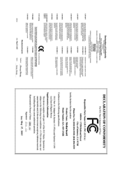
Motherboard GA-8I915ME May 27, 2005 Motherboard GA-8I915ME May 27, 2005
Motherboard GA-8I915ME May 27, 2005 Motherboard GA-8I915ME May 27, 2005

Manual
Page 4
Table of Content GA-8I915ME Series Motherboard Layout 6 Block Diagram ...7 Chapter 1 Hardware Installation 9 1-1 Considerations Prior to Installation 9 1-2 Feature Summary 10 1-3 Installation of the CPU and Heatsink 12 ...is G.E.A.R 17 1-5-2 Graphics Card Support List 17 1-6 I/O Back Panel Introduction 20 1-7 Connectors Introduction 21 Chapter 2 BIOS Setup 33 The Main Menu ...34 (For example: GA-8I915ME-GV / BIOS Ver.: F2 34 2-1 Standard CMOS Features 36 2-2 Advanced BIOS Features 38 2-3 IntegratedPeripherals 40 2-4 Power Management Setup 42 2-5 PnP/PCI Configurations 44 2-6 PC...
Table of Content GA-8I915ME Series Motherboard Layout 6 Block Diagram ...7 Chapter 1 Hardware Installation 9 1-1 Considerations Prior to Installation 9 1-2 Feature Summary 10 1-3 Installation of the CPU and Heatsink 12 ...is G.E.A.R 17 1-5-2 Graphics Card Support List 17 1-6 I/O Back Panel Introduction 20 1-7 Connectors Introduction 21 Chapter 2 BIOS Setup 33 The Main Menu ...34 (For example: GA-8I915ME-GV / BIOS Ver.: F2 34 2-1 Standard CMOS Features 36 2-2 Advanced BIOS Features 38 2-3 IntegratedPeripherals 40 2-4 Power Management Setup 42 2-5 PnP/PCI Configurations 44 2-6 PC...
Manual
Page 6
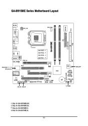
Only for GA-8I915ME-GV. GA-8I915ME Series Motherboard Layout IT8712F CI KB_MS ATX_12V CPU_FAN COM1 LPT GA-8I915ME ATX SYS_FAN FDD VGA LGA775 R_USB LAN USB F_AUDIO AUDIO1 SUR_CEN PCIE_16 Intel 915GV Intel 915GL Intel 910GL Intel 915G DIMM1 DIMM2 IDE RTL8100C RTL8110S PCI1 GEAR ICH6 -C -G -GL -GV PCI2 CODEC SPDIF_IO BUZZER F_USB1 F_USB2 BAT COM2 WOL CLR_CMOS BIOS SATA2 SATA0 BIOS_WP PWR_LED CD_IN AUX_IN F_PANEL Only for GA-8I915ME-G. - 6 - Only for GA-8I915ME-GL. Only for GA-8I915ME-C.
Only for GA-8I915ME-GV. GA-8I915ME Series Motherboard Layout IT8712F CI KB_MS ATX_12V CPU_FAN COM1 LPT GA-8I915ME ATX SYS_FAN FDD VGA LGA775 R_USB LAN USB F_AUDIO AUDIO1 SUR_CEN PCIE_16 Intel 915GV Intel 915GL Intel 910GL Intel 915G DIMM1 DIMM2 IDE RTL8100C RTL8110S PCI1 GEAR ICH6 -C -G -GL -GV PCI2 CODEC SPDIF_IO BUZZER F_USB1 F_USB2 BAT COM2 WOL CLR_CMOS BIOS SATA2 SATA0 BIOS_WP PWR_LED CD_IN AUX_IN F_PANEL Only for GA-8I915ME-G. - 6 - Only for GA-8I915ME-GL. Only for GA-8I915ME-C.
Manual
Page 7
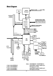
Only for GA-8I915ME-GV. GA-8I915ME-G supports transfer up to PCI Express x16 mode. Block Diagram VGA LGA775 Processor CPUCLK+/-(200 /133 MHz) PCI-ECLK (100MHz) Host Interface PCI Express x16 ... Ports AC97 Link AC97 CODEC 8 USB Ports 24MHz 33MHz PS/2 KB/Mouse PCICLK (33MHz) MIC Line-Out Line-In SPDIF In SPDIF Out Only for GA-8I915ME-GL. GA-8I915ME-GV / GA-8I915ME-GL / GA-8I915ME-C supports transfer up to PCI Express x4 mode. Only for...
Only for GA-8I915ME-GV. GA-8I915ME-G supports transfer up to PCI Express x16 mode. Block Diagram VGA LGA775 Processor CPUCLK+/-(200 /133 MHz) PCI-ECLK (100MHz) Host Interface PCI Express x16 ... Ports AC97 Link AC97 CODEC 8 USB Ports 24MHz 33MHz PS/2 KB/Mouse PCICLK (33MHz) MIC Line-Out Line-In SPDIF In SPDIF Out Only for GA-8I915ME-GL. GA-8I915ME-GV / GA-8I915ME-GL / GA-8I915ME-C supports transfer up to PCI Express x4 mode. Only for...
Manual
Page 10
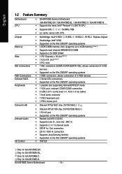
...In / AUX In connection Š Supports Jack-Sensing function Š Supported on the Win 2000/XP operating systems Š IT8712F Only for GA-8I915ME-C. slot (Note 3) Š 2 PCI slots Š 1 IDE connection (UDMA 33/ATA 66/ATA 100), allows connection of 2 ...5V DDR DIMM Š 1 PCI Express x 16 slot (Note 2) Š 1 G.E.A.R. English 1-2 Feature Summary Motherboard CPU Š GA-8I915ME Series motherboard -GA-8I915ME-GV / GA-8I915ME-GL / GA-8I915ME-C / GA-8I915ME-G Š Supports the latest Intel® Pentium® 4 LGA775 CPU Š Supports 800 / 533MHz FSB Š L2 cache varies...
...In / AUX In connection Š Supports Jack-Sensing function Š Supported on the Win 2000/XP operating systems Š IT8712F Only for GA-8I915ME-C. slot (Note 3) Š 2 PCI slots Š 1 IDE connection (UDMA 33/ATA 66/ATA 100), allows connection of 2 ...5V DDR DIMM Š 1 PCI Express x 16 slot (Note 2) Š 1 G.E.A.R. English 1-2 Feature Summary Motherboard CPU Š GA-8I915ME Series motherboard -GA-8I915ME-GV / GA-8I915ME-GL / GA-8I915ME-C / GA-8I915ME-G Š Supports the latest Intel® Pentium® 4 LGA775 CPU Š Supports 800 / 533MHz FSB Š L2 cache varies...
Manual
Page 11
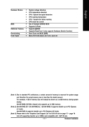
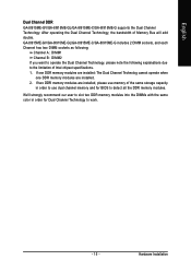
... factor; 24.4 cm x 23.6 cm (Note 1) Due to 33MHz and compatible with AGP 8X slot. - 11 - GA-8I915ME-C(910GL chipset) only supports up to 2GB memory. (Note 2) GA-8I915ME-GV / GA-8I915ME-GL / GA-8I915ME-C supports transfer up to PCI Express x16 mode. (Note 3) Please refer to PCI Express x4 mode.... GA-8I915ME-G supports transfer up to the "Graphics Card Support List" for system usage and therefore the...
... factor; 24.4 cm x 23.6 cm (Note 1) Due to 33MHz and compatible with AGP 8X slot. - 11 - GA-8I915ME-C(910GL chipset) only supports up to 2GB memory. (Note 2) GA-8I915ME-GV / GA-8I915ME-GL / GA-8I915ME-C supports transfer up to PCI Express x16 mode. (Note 3) Please refer to PCI Express x4 mode.... GA-8I915ME-G supports transfer up to the "Graphics Card Support List" for system usage and therefore the...
Manual
Page 12
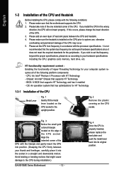
... for HT Technology 1-3-1 Installation of the CPU Metal Lever Fig. 1 Gently lift the metal lever located on the CPU prior to the CPU during installation.) GA-8I915ME Series Motherboard - 12 - Please take note of the one indented corner of the CPU. 3. If you wish to set the CPU host frequency in the...
... for HT Technology 1-3-1 Installation of the CPU Metal Lever Fig. 1 Gently lift the metal lever located on the CPU prior to the CPU during installation.) GA-8I915ME Series Motherboard - 12 - Please take note of the one indented corner of the CPU. 3. If you wish to set the CPU host frequency in the...
Manual
Page 14
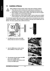
... damage. 3. The DIMM slot has a notch, so the DIMM memory module can differ with the following conditions: 1. The memory capacity used . 2. Then push it down. 3. GA-8I915ME Series Motherboard - 14 - Please make sure that memory of similar capacity, specifications and brand be inserted only in one direction. The motherboard supports DDR memory...
... damage. 3. The DIMM slot has a notch, so the DIMM memory module can differ with the following conditions: 1. The memory capacity used . 2. Then push it down. 3. GA-8I915ME Series Motherboard - 14 - Please make sure that memory of similar capacity, specifications and brand be inserted only in one direction. The motherboard supports DDR memory...
Manual
Page 15
...storage capacity in order for BIOS to detect all the DDR memory modules. Hardware Installation English Dual Channel DDR GA-8I915ME-GV/GA-8I915ME-GL/GA-8I915ME-C/GA-8I915ME-G supports the Dual Channel Technology. If one DDR memory modules are installed: The Dual Channel Technolog cannot ...and for Dual Channel Technology to the limitation of Memory Bus will add double. If two DDR memory modules are installed. 2. GA-8I915ME-GV/GA-8I915ME-GL/GA-8I915ME-C/GA-8I915ME-G includes 2 DIMM sockets, and each Channel has two DIMM sockets as following: Channel A : DIMM1 Channel B : DIMM2...
...storage capacity in order for BIOS to detect all the DDR memory modules. Hardware Installation English Dual Channel DDR GA-8I915ME-GV/GA-8I915ME-GL/GA-8I915ME-C/GA-8I915ME-G supports the Dual Channel Technology. If one DDR memory modules are installed: The Dual Channel Technolog cannot ...and for Dual Channel Technology to the limitation of Memory Bus will add double. If two DDR memory modules are installed. 2. GA-8I915ME-GV/GA-8I915ME-GL/GA-8I915ME-C/GA-8I915ME-G includes 2 DIMM sockets, and each Channel has two DIMM sockets as following: Channel A : DIMM1 Channel B : DIMM2...
Manual
Page 16
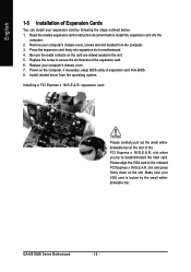
English 1-5 Installation of the expansion card. 6. Read the related expansion card's instruction document before install the expansion card into expansion slot in the slot. 5. GA-8I915ME Series Motherboard - 16 - Install related driver from the computer. 3. slot when you try to the onboard PCI Express x 16/G.E.A.R. Replace the screw to secure the ...
English 1-5 Installation of the expansion card. 6. Read the related expansion card's instruction document before install the expansion card into expansion slot in the slot. 5. GA-8I915ME Series Motherboard - 16 - Install related driver from the computer. 3. slot when you try to the onboard PCI Express x 16/G.E.A.R. Replace the screw to secure the ...
Manual
Page 17
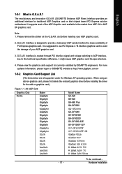
... 1-1. 4X AGP Card Graphics Chip Nvidia Maker Gigabyte Gigabyte Gigabyte Gigabyte Model Name GA-620 GA-622 GA-660 Plus GA-GF2560 Gigabyte Gigabyte Gigabyte Gigabyte Gigabyte Gigabyte GA-GF2000 GA-GF1280 GV-GF2010D GA-GF3000D GV-GF1280-32E GV-GF1280T-32P Gigabyte Gigabyte ELSA G V-GF3200TF G V-GF3500TF-GH Gladiac ... It supports most of your AGP graphics card. 2. G.E.A.R. Please view the graphics cards support list currently validated by GIGABYTE enginneers. English 1-5-1 What is designed to provide a temporary AGP solution before the mass availability of PCI Express graphics ...
... 1-1. 4X AGP Card Graphics Chip Nvidia Maker Gigabyte Gigabyte Gigabyte Gigabyte Model Name GA-620 GA-622 GA-660 Plus GA-GF2560 Gigabyte Gigabyte Gigabyte Gigabyte Gigabyte Gigabyte GA-GF2000 GA-GF1280 GV-GF2010D GA-GF3000D GV-GF1280-32E GV-GF1280T-32P Gigabyte Gigabyte ELSA G V-GF3200TF G V-GF3500TF-GH Gladiac ... It supports most of your AGP graphics card. 2. G.E.A.R. Please view the graphics cards support list currently validated by GIGABYTE enginneers. English 1-5-1 What is designed to provide a temporary AGP solution before the mass availability of PCI Express graphics ...
Manual
Page 20
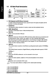
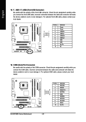
...In jack. MIC In Microphone can be connected to MIC In jack. can use audio software to serial-based mouse or data processing devices. GA-8I915ME Series Motherboard - 20 - COM 1 (Serial Port) Connects to configure 2-/4-/6- have a standard USB interface. The provided Internet connection is fast ...for possible patch or driver upgrade. Line In Devices like CD-ROM, walkman etc. channel audio functioning. Only for GA-8I915ME-G. Only for GA-8I915ME-GV. USB port Before you connect your device(s) into USB connector(s), please make sure your OS or device(s) vendors. Only...
...In jack. MIC In Microphone can be connected to MIC In jack. can use audio software to serial-based mouse or data processing devices. GA-8I915ME Series Motherboard - 20 - COM 1 (Serial Port) Connects to configure 2-/4-/6- have a standard USB interface. The provided Internet connection is fast ...for possible patch or driver upgrade. Line In Devices like CD-ROM, walkman etc. channel audio functioning. Only for GA-8I915ME-G. Only for GA-8I915ME-GV. USB port Before you connect your device(s) into USB connector(s), please make sure your OS or device(s) vendors. Only...
Manual
Page 22
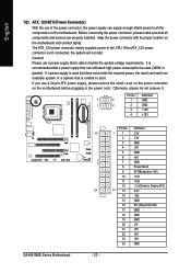
... 3.3V(Only for 24pins ATX) 3.3V -12V GND PS_ON(soft On/Off) GND GND GND -5V +5V +5V +5V GND Definition 3 4 1 GND 1 2 2 GND 3 +12V 4 +12V GA-8I915ME Series Motherboard 13 24 - 22 - Align the power connector with its proper location on the motherboard before plugging in the power cord ; English 1/2) ATX_12V/ATX...
... 3.3V(Only for 24pins ATX) 3.3V -12V GND PS_ON(soft On/Off) GND GND GND -5V +5V +5V +5V GND Definition 3 4 1 GND 1 2 2 GND 3 +12V 4 +12V GA-8I915ME Series Motherboard 13 24 - 22 - Align the power connector with its proper location on the motherboard before plugging in the power cord ; English 1/2) ATX_12V/ATX...
Manual
Page 24
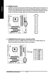
... the Serial ATA and install the proper driver in order to the computer via an IDE connector. Definition 1 GND 1 7 2 TXP 3 TXN 4 GND 5 RXN 6 RXP 7 GND GA-8I915ME Series Motherboard - 24 - One IDE connector can provide up to two IDE devices (hard drive or optical drive).
... the Serial ATA and install the proper driver in order to the computer via an IDE connector. Definition 1 GND 1 7 2 TXP 3 TXN 4 GND 5 RXN 6 RXP 7 GND GA-8I915ME Series Motherboard - 24 - One IDE connector can provide up to two IDE devices (hard drive or optical drive).
Manual
Page 26
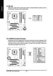
... remove the jumpers on /off. Pin No. Definition 1 MIC 10 9 2 GND 3 MIC_BIAS 4 POWER 2 1 5 FrontAudio(R) 6 Rear Audio (R)/ Return R 7 NC 8 No Pin 9 FrontAudio (L) 10 Rear Audio (L)/ Return L GA-8I915ME Series Motherboard - 26 - Pin No.
... remove the jumpers on /off. Pin No. Definition 1 MIC 10 9 2 GND 3 MIC_BIAS 4 POWER 2 1 5 FrontAudio(R) 6 Rear Audio (R)/ Return R 7 NC 8 No Pin 9 FrontAudio (L) 10 Rear Audio (L)/ Return L GA-8I915ME Series Motherboard - 26 - Pin No.
Manual
Page 28
... will make the device unable to work or even damage it . Definition 1 NDCD B- 2 NSIN B 2 10 3 NSOUT B 4 NDTR B- 1 9 5 GND 6 NDSR B- 7 NRTS B- 8 NCTS B- 9 NRI B- 10 No Pin GA-8I915ME Series Motherboard - 28 - Pin No. Check the pin assignment carefully while you connect the COM cable, incorrect connection between the cable and connector will make...
... will make the device unable to work or even damage it . Definition 1 NDCD B- 2 NSIN B 2 10 3 NSOUT B 4 NDTR B- 1 9 5 GND 6 NDSR B- 7 NRTS B- 8 NCTS B- 9 NRI B- 10 No Pin GA-8I915ME Series Motherboard - 28 - Pin No. Check the pin assignment carefully while you connect the COM cable, incorrect connection between the cable and connector will make...
Manual
Page 30
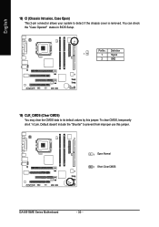
Default doesn't include the "Shunter" to detect if the chassis cover is removed. Pin No. English 18) CI (Chassis Intrusion, Case Open) This 2-pin connector allows your system to prevent from improper use this jumper. You can check the "Case Opened" status in BIOS Setup. To clear CMOS, temporarily short 1-2 pin. Definition 1 1 Signal 2 GND 19) CLR_CMOS (Clear CMOS) You may clear the CMOS data to its default values by this jumper. 1 Open: Normal 1 Short :Clear CMOS GA-8I915ME Series Motherboard - 30 -
Default doesn't include the "Shunter" to detect if the chassis cover is removed. Pin No. English 18) CI (Chassis Intrusion, Case Open) This 2-pin connector allows your system to prevent from improper use this jumper. You can check the "Case Opened" status in BIOS Setup. To clear CMOS, temporarily short 1-2 pin. Definition 1 1 Signal 2 GND 19) CLR_CMOS (Clear CMOS) You may clear the CMOS data to its default values by this jumper. 1 Open: Normal 1 Short :Clear CMOS GA-8I915ME Series Motherboard - 30 -
Manual
Page 34
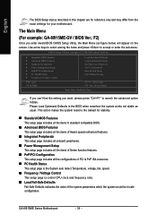
... User Password Save & Exit Setup Exit Without Saving KLJI: Select Item F10: Save & Exit Setup Time, Date, Hard Disk Type... The Main Menu (For example: GA-8I915ME-GV / BIOS Ver.: F2) Once you want, please press "Ctrl+F1" to accept or enter the sub-menu...
... User Password Save & Exit Setup Exit Without Saving KLJI: Select Item F10: Save & Exit Setup Time, Date, Hard Disk Type... The Main Menu (For example: GA-8I915ME-GV / BIOS Ver.: F2) Once you want, please press "Ctrl+F1" to accept or enter the sub-menu...
Manual
Page 36
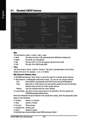
... of sectors If a hard disk has not been installed, select NONE and press . Enter the appropriate option based on the outside drive casing. For example, 1 p.m. GA-8I915ME Series Motherboard - 36 - to Dec. to Sat. Week The week, from 1999 through 2098 Time The times format in the month) 1999 to select this...
... of sectors If a hard disk has not been installed, select NONE and press . Enter the appropriate option based on the outside drive casing. For example, 1 p.m. GA-8I915ME Series Motherboard - 36 - to Dec. to Sat. Week The week, from 1999 through 2098 Time The times format in the month) 1999 to select this...

