Manual
Page 1
GA-8I865GMFK-775 / GA-8I865GMK-775 Intel® Pentium® 4 LGA775 Processor Motherboard User's Manual Rev. 1001 12ME-I865GMFKT-1001
GA-8I865GMFK-775 / GA-8I865GMK-775 Intel® Pentium® 4 LGA775 Processor Motherboard User's Manual Rev. 1001 12ME-I865GMFKT-1001
Manual
Page 2
Motherboard GA-8I865GMFK-775 / GA-8I865GMK-775 May. 31, 2005 Motherboard GA-8I865GMFK-775 / GA-8I865GMK-775 May. 31, 2005
Motherboard GA-8I865GMFK-775 / GA-8I865GMK-775 May. 31, 2005 Motherboard GA-8I865GMFK-775 / GA-8I865GMK-775 May. 31, 2005
Manual
Page 4
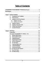
Table of Contents GA-8I865GMFK-775/GA-8I865GMK-775 Motherboard Layout 6 Block Diagram ...7 Chapter 1 Hardware Installation 9 1-1 Considerations Prior to Installation 9 1-2 Feature Summary 10 1-3 Installation of the CPU and Heatsink 12 1-3-1... 1-5 Installation of Expansion Cards 16 1-6 I/O Back Panel Introduction 17 1-7 Connectors Introduction 18 Chapter 2 BIOS Setup 29 The Main Menu ...30 (For example: GA-8I865GMFK-775 / BIOS Ver. : E2 30 2-1 Standard CMOS Features 32 2-2 Advanced BIOS Features 34 2-3 IntegratedPeripherals 36 2-4 Power Management Setup 39 2-5 PnP/PCI Configurations...
Table of Contents GA-8I865GMFK-775/GA-8I865GMK-775 Motherboard Layout 6 Block Diagram ...7 Chapter 1 Hardware Installation 9 1-1 Considerations Prior to Installation 9 1-2 Feature Summary 10 1-3 Installation of the CPU and Heatsink 12 1-3-1... 1-5 Installation of Expansion Cards 16 1-6 I/O Back Panel Introduction 17 1-7 Connectors Introduction 18 Chapter 2 BIOS Setup 29 The Main Menu ...30 (For example: GA-8I865GMFK-775 / BIOS Ver. : E2 30 2-1 Standard CMOS Features 32 2-2 Advanced BIOS Features 34 2-3 IntegratedPeripherals 36 2-4 Power Management Setup 39 2-5 PnP/PCI Configurations...
Manual
Page 6
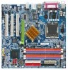
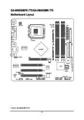
IDE1 GA-8I865GMFK-775/GA-8I865GMK-775 Motherboard Layout KB_MS ATX_12V CPU_FAN LGA775 ATX FDD GA-8I865GMFK-775 * (or GA-8I865GMK-775) DDR1 DDR2 DDR3 DDR4 IDE2 LPT LAN VGA COMA R_USB LPC47M997 Intel 865G USB AUDIO F_AUDIO EP82562G IR CODEC SPDIF CD_IN AGP BAT COMB PCI1 BIOS PCI2 TSB43AB23* PCI3 F2_1394* F1_1394* ICH5 SATA1 SATA0 PWR_LED F_USB1 F_USB2 F_PANEL CLR_CMOS SYS_FAN * Only for GA-8I865GMFK-775. - 6 -
IDE1 GA-8I865GMFK-775/GA-8I865GMK-775 Motherboard Layout KB_MS ATX_12V CPU_FAN LGA775 ATX FDD GA-8I865GMFK-775 * (or GA-8I865GMK-775) DDR1 DDR2 DDR3 DDR4 IDE2 LPT LAN VGA COMA R_USB LPC47M997 Intel 865G USB AUDIO F_AUDIO EP82562G IR CODEC SPDIF CD_IN AGP BAT COMB PCI1 BIOS PCI2 TSB43AB23* PCI3 F2_1394* F1_1394* ICH5 SATA1 SATA0 PWR_LED F_USB1 F_USB2 F_PANEL CLR_CMOS SYS_FAN * Only for GA-8I865GMFK-775. - 6 -
Manual
Page 9
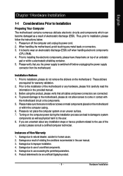
... Installation Notices 1. Please make sure there are required for warranty validation. 2. If you the power supply is best to be an unofficial Gigabyte product. - 9 - Prior to installing the electronic components, please have a problem related to come in the user manual. 3. Prior ...become damaged as physical harm to improper installation. 4. To prevent damage to natural disaster, accident or human cause. 2. Turning on the motherboard or within a electrostatic shielding container. 5. Damage due to the user. 8. Product determined to wear an electrostatic discharge (ESD) cuff...
... Installation Notices 1. Please make sure there are required for warranty validation. 2. If you the power supply is best to be an unofficial Gigabyte product. - 9 - Prior to installing the electronic components, please have a problem related to come in the user manual. 3. Prior ...become damaged as physical harm to improper installation. 4. To prevent damage to natural disaster, accident or human cause. 2. Turning on the motherboard or within a electrostatic shielding container. 5. Damage due to the user. 8. Product determined to wear an electrostatic discharge (ESD) cuff...
Manual
Page 10
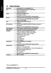
...; Supports 2 / 4 / 5.1 channel audio Š Supports Line In (Rear Speaker Out) ; GA-8I865GM(F)K-775 Motherboard - 10 - English 1-2 Feature Summary Motherboard CPU Chipset Memory Slots IDE Connections FDD Connections Onboard SATA Peripherals Onboard LAN Onboard Audio I/O Control Š GA-8I865GMK-775 or GA-8I865GMFK-775 Š Supports the latest Intel® Pentium® 4 LGA775 CPU Š Supports 800... chip (10/100Mbit) Š 1 RJ 45 port Š Supported on the Win 98/ME2000/XP operating systems Š SMSC LPC47M997 * Only for GA-8I865GMFK-775. Line Out (Front Speaker Out) ;
...; Supports 2 / 4 / 5.1 channel audio Š Supports Line In (Rear Speaker Out) ; GA-8I865GM(F)K-775 Motherboard - 10 - English 1-2 Feature Summary Motherboard CPU Chipset Memory Slots IDE Connections FDD Connections Onboard SATA Peripherals Onboard LAN Onboard Audio I/O Control Š GA-8I865GMK-775 or GA-8I865GMFK-775 Š Supports the latest Intel® Pentium® 4 LGA775 CPU Š Supports 800... chip (10/100Mbit) Š 1 RJ 45 port Š Supported on the Win 98/ME2000/XP operating systems Š SMSC LPC47M997 * Only for GA-8I865GMFK-775. Line Out (Front Speaker Out) ;
Manual
Page 12
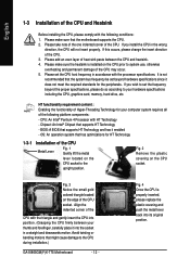
... corner of the CPU. 3. CPU: An Intel® Pentium 4 Processor with the following platform components: - BIOS: A BIOS that the motherboard supports the CPU. 2. If this occurs, please change the insert direction of the CPU. Please make sure that supports HT Technology and has... of the following conditions: 1. Fig. 3 Notice the small gold colored triangle located on the CPU prior to the CPU during installation.) GA-8I865GM(F)K-775 Motherboard - 12 - Fig. 4 Once the CPU is not recommended that might cause damage to system use, otherwise overheating and permanent damage of...
... corner of the CPU. 3. CPU: An Intel® Pentium 4 Processor with the following platform components: - BIOS: A BIOS that the motherboard supports the CPU. 2. If this occurs, please change the insert direction of the CPU. Please make sure that supports HT Technology and has... of the following conditions: 1. Fig. 3 Notice the small gold colored triangle located on the CPU prior to the CPU during installation.) GA-8I865GM(F)K-775 Motherboard - 12 - Fig. 4 Once the CPU is not recommended that might cause damage to system use, otherwise overheating and permanent damage of...
Manual
Page 13
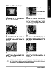
... used for Intel boxed fan) Fig. 3 Place the heatsink atop the CPU and make sure the push pins aim to the pin hole on the motherboard. To prevent such an occurrence, it is only for heat dissipation or using extreme care when removing the heatsink. - 13 - Fig. 2 (Turning the push pin... Push Pin Fig.1 Please apply an even layer of heatsink paste on the surface of the heatsink to the CPU fan header located on the motherboard. The heatsink may adhere to the CPU as the picture, the installation is to install.) Please note the direction of...
... used for Intel boxed fan) Fig. 3 Place the heatsink atop the CPU and make sure the push pins aim to the pin hole on the motherboard. To prevent such an occurrence, it is only for heat dissipation or using extreme care when removing the heatsink. - 13 - Fig. 2 (Turning the push pin... Push Pin Fig.1 Please apply an even layer of heatsink paste on the surface of the heatsink to the CPU fan header located on the motherboard. The heatsink may adhere to the CPU as the picture, the installation is to install.) Please note the direction of...
Manual
Page 14
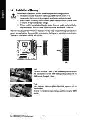
... one direction. Fig.2 Close the plastic clip at both edges of the DIMM sockets to remove the DIMM module. GA-8I865GM(F)K-775 Motherboard - 14 - Memory modules are unable to prevent hardware damage. 3. Insert the DIMM memory module vertically into the DIMM socket. The... motherboard supports DDR memory modules, whereby BIOS will automatically detect memory capacity and specifications. Please make sure that they can differ ...
... one direction. Fig.2 Close the plastic clip at both edges of the DIMM sockets to remove the DIMM module. GA-8I865GM(F)K-775 Motherboard - 14 - Memory modules are unable to prevent hardware damage. 3. Insert the DIMM memory module vertically into the DIMM socket. The... motherboard supports DDR memory modules, whereby BIOS will automatically detect memory capacity and specifications. Please make sure that they can differ ...
Manual
Page 16
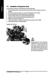
... bracket of the expansion card. 6. Press the expansion card firmly into the computer. 2. Install related driver from BIOS. 8. GA-8I865GM(F)K-775 Motherboard - 16 - Be sure the metal contacts on the card are indeed seated in motherboard. 4. Replace the screw to install/uninstall the VGA card. Replace your computer's chassis cover, screws and slot bracket...
... bracket of the expansion card. 6. Press the expansion card firmly into the computer. 2. Install related driver from BIOS. 8. GA-8I865GM(F)K-775 Motherboard - 16 - Be sure the metal contacts on the card are indeed seated in motherboard. 4. Replace the screw to install/uninstall the VGA card. Replace your computer's chassis cover, screws and slot bracket...
Manual
Page 18
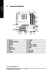
English 1-7 Connectors Introduction 1 3 2 5 6 10 8 17 4 16 12 7 18 11 15 14 13 9 1) ATX_12V 2) ATX (Power Connector) 3) CPU_FAN 4) SYS_FAN 5) FDD 6) IDE1 / IDE2 7) SATA0 / SATA1 8) BAT 9) F_PANEL 10) F_AUDIO 11) CD_IN 12) SPDIF 13) F_USB1 / F_USB2 14) F1_1394* / F2_1394* 15) COMB 16) IR 17) CLR_CMOS 18) PWR_LED * Only for GA-8I865GMFK-775. GA-8I865GM(F)K-775 Motherboard - 18 -
English 1-7 Connectors Introduction 1 3 2 5 6 10 8 17 4 16 12 7 18 11 15 14 13 9 1) ATX_12V 2) ATX (Power Connector) 3) CPU_FAN 4) SYS_FAN 5) FDD 6) IDE1 / IDE2 7) SATA0 / SATA1 8) BAT 9) F_PANEL 10) F_AUDIO 11) CD_IN 12) SPDIF 13) F_USB1 / F_USB2 14) F1_1394* / F2_1394* 15) COMB 16) IR 17) CLR_CMOS 18) PWR_LED * Only for GA-8I865GMFK-775. GA-8I865GM(F)K-775 Motherboard - 18 -

Manual
Page 19
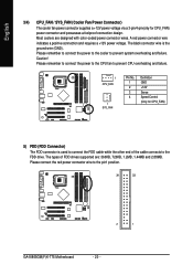
... components and devices are properly installed. If the ATX_12V power connector is unable to handle the system voltage requirements. Please remove the sticker on the motherboard before plugging in while the ATX power supplier is able to start . Definition 11 1 1 3.3V 2 3.3V 3 GND 4 +5V 5 GND...or a system that is 24 pins; Caution! Hardware Installation It is recommended that a power supply that all the components on the motherboard and connect tightly. English 1/2) ATX_12V/ATX (Power Connector) With the use a power supply that is not connected, the system ...
... components and devices are properly installed. If the ATX_12V power connector is unable to handle the system voltage requirements. Please remove the sticker on the motherboard before plugging in while the ATX power supplier is able to start . Definition 11 1 1 3.3V 2 3.3V 3 GND 4 +5V 5 GND...or a system that is 24 pins; Caution! Hardware Installation It is recommended that a power supply that all the components on the motherboard and connect tightly. English 1/2) ATX_12V/ATX (Power Connector) With the use a power supply that is not connected, the system ...
Manual
Page 20
... drives supported are designed with color-coded power connector wires. Please remember to connect the power to the cooler to the pin1 position. 34 33 2 1 GA-8I865GM(F)K-775 Motherboard - 20 - English 3/4) CPU_FAN / SYS_FAN (Cooler Fan Power Connector) The cooler fan power connector supplies a +12V power voltage via a 3-pin/4-pin(only for CPU_FAN) 5) FDD...
... drives supported are designed with color-coded power connector wires. Please remember to connect the power to the cooler to the pin1 position. 34 33 2 1 GA-8I865GM(F)K-775 Motherboard - 20 - English 3/4) CPU_FAN / SYS_FAN (Cooler Fan Power Connector) The cooler fan power connector supplies a +12V power voltage via a 3-pin/4-pin(only for CPU_FAN) 5) FDD...
Manual
Page 22
...+ MSG- RESRES+ NC HD (IDE Hard Disk Active LED) SPEAK (Speaker Connector) RES (Reset Switch) PW (Power Switch) MSG(Message LED/Power/Sleep LED) NC GA-8I865GM(F)K-775 Motherboard IDE Hard Disk Active LED Reset Switch Pin 1: LED anode(+) Pin 2: LED cathode(-) Pin 1: Power Pin 2- If you can use a metal object to connect...
...+ MSG- RESRES+ NC HD (IDE Hard Disk Active LED) SPEAK (Speaker Connector) RES (Reset Switch) PW (Power Switch) MSG(Message LED/Power/Sleep LED) NC GA-8I865GM(F)K-775 Motherboard IDE Hard Disk Active LED Reset Switch Pin 1: LED anode(+) Pin 2: LED cathode(-) Pin 1: Power Pin 2- If you can use a metal object to connect...
Manual
Page 24
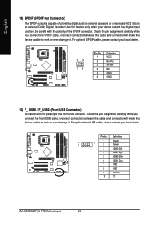
... the polarity of the SPDIF connector. Definition 1 Power 2 10 1 9 2 Power 3 USB0 DX- 4 USB1 Dy- 5 USB0 DX+ 6 USB1 Dy+ 7 GND 8 GND 9 No Pin 10 NC GA-8I865GM(F)K-775 Motherboard - 24 - Use this feature only when your local dealer. Pin No. English 12) SPDIF (SPDIF Out Connector) The SPDIF output is capable of providing digital...
... the polarity of the SPDIF connector. Definition 1 Power 2 10 1 9 2 Power 3 USB0 DX- 4 USB1 Dy- 5 USB0 DX+ 6 USB1 Dy+ 7 GND 8 GND 9 No Pin 10 NC GA-8I865GM(F)K-775 Motherboard - 24 - Use this feature only when your local dealer. Pin No. English 12) SPDIF (SPDIF Out Connector) The SPDIF output is capable of providing digital...
Manual
Page 26
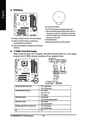
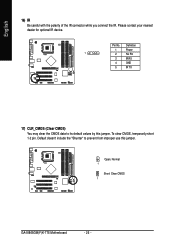
Definition 1 Power 1 2 No Pin 3 IR RX 4 GND 5 IR TX 17) CLR_CMOS (Clear CMOS) You may clear the CMOS data to prevent from improper use this jumper. English 16) IR Be careful with the polarity of the IR connector while you connect the IR. Pin No. Please contact your nearest dealer for optional IR device. To clear CMOS, temporarily short 1-2 pin. Default doesn't include the "Shunter" to its default values by this jumper. Open: Normal 1 Short: Clear CMOS 1 GA-8I865GM(F)K-775 Motherboard - 26 -
Definition 1 Power 1 2 No Pin 3 IR RX 4 GND 5 IR TX 17) CLR_CMOS (Clear CMOS) You may clear the CMOS data to prevent from improper use this jumper. English 16) IR Be careful with the polarity of the IR connector while you connect the IR. Pin No. Please contact your nearest dealer for optional IR device. To clear CMOS, temporarily short 1-2 pin. Default doesn't include the "Shunter" to its default values by this jumper. Open: Normal 1 Short: Clear CMOS 1 GA-8I865GM(F)K-775 Motherboard - 26 -
Manual
Page 29
... Test) will take you save changes into CMOS Status Page Setup Menu and Option Page Setup Menu - Q-Flash allows the user to a new BIOS, either Gigabyte's Q-Flash or @BIOS utility can enter the BIOS setup screen by pressing "Ctrl + F1". To exit the Help Window press . - 29 - You can... changes, only for the first time, it is recommended that you to its original settings. When the power is displayed at the bottom of the motherboard. English Chapter 2 BIOS Setup BIOS (Basic Input and Output System) includes a CMOS SETUP utility which allows user to configure required settings or to ...
... Test) will take you save changes into CMOS Status Page Setup Menu and Option Page Setup Menu - Q-Flash allows the user to a new BIOS, either Gigabyte's Q-Flash or @BIOS utility can enter the BIOS setup screen by pressing "Ctrl + F1". To exit the Help Window press . - 29 - You can... changes, only for the first time, it is recommended that you to its original settings. When the power is displayed at the bottom of the motherboard. English Chapter 2 BIOS Setup BIOS (Basic Input and Output System) includes a CMOS SETUP utility which allows user to configure required settings or to ...
Manual
Page 30
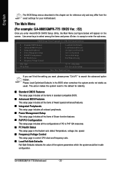
... parameters which the system would be in the BIOS when somehow the system works not stable as figure below) will appear on the screen. GA-8I865GM(F)K-775 Motherboard - 30 - CMOS Setup Utility-Copyright (C) 1984-2005 Award Software ` Standard CMOS Features ` Advanced BIOS Features ` Integrated Peripherals ` Power ... Setup Exit Without Saving KLJI: Select Item F10: Save & Exit Setup Time, Date, Hard Disk Type... The Main Menu (For example: GA-8I865GMFK-775 / BIOS Ver. : E2) Once you want, please press "Ctrl+F1" to search the advanced option hidden. Please Load Optimized Defaults in...
... parameters which the system would be in the BIOS when somehow the system works not stable as figure below) will appear on the screen. GA-8I865GM(F)K-775 Motherboard - 30 - CMOS Setup Utility-Copyright (C) 1984-2005 Award Software ` Standard CMOS Features ` Advanced BIOS Features ` Integrated Peripherals ` Power ... Setup Exit Without Saving KLJI: Select Item F10: Save & Exit Setup Time, Date, Hard Disk Type... The Main Menu (For example: GA-8I865GMFK-775 / BIOS Ver. : E2) Once you want, please press "Ctrl+F1" to search the advanced option hidden. Please Load Optimized Defaults in...
Manual
Page 32
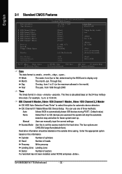
... sectors If a hard disk has not been installed, select NONE and press . You can manually input the correct settings. The time is 13:00:00. GA-8I865GM(F)K-775 Motherboard - 32 - Day The day, from 1 to 31 (or the maximum allowed in the month) Base Memory Extended Memory Total Memory KLJI: Move Enter: Select...
... sectors If a hard disk has not been installed, select NONE and press . You can manually input the correct settings. The time is 13:00:00. GA-8I865GM(F)K-775 Motherboard - 32 - Day The day, from 1 to 31 (or the maximum allowed in the month) Base Memory Extended Memory Total Memory KLJI: Move Enter: Select...
Manual
Page 33
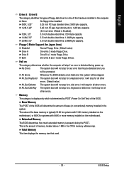
..., 3.5" 2.88M, 3.5" 3.5 inch double-sided drive; 1.44M byte capacity. 3.5 inch double-sided drive; 2.88M byte capacity. Halt on the motherboard. The system boot will not stop if an error is present during power up. Extended Memory The BIOS determines how much extended memory is detected... Area) Disabled Drive A Drive B Normal Floppy Drive. (Default value) Drive A is typically 512K for systems with 512K memory installed on the motherboard, or 640K for a keyboard error; No Errors The system boot will determine the amount of base (or conventional) memory installed in the computer...
..., 3.5" 2.88M, 3.5" 3.5 inch double-sided drive; 1.44M byte capacity. 3.5 inch double-sided drive; 2.88M byte capacity. Halt on the motherboard. The system boot will not stop if an error is present during power up. Extended Memory The BIOS determines how much extended memory is detected... Area) Disabled Drive A Drive B Normal Floppy Drive. (Default value) Drive A is typically 512K for systems with 512K memory installed on the motherboard, or 640K for a keyboard error; No Errors The system boot will determine the amount of base (or conventional) memory installed in the computer...


