
Manual
Page 1
GA-8AENXP-DW Intel® Pentium® 4 LGA775 Processor Motherboard User's Manual Rev. 1001 12ME-8AENXPDW-1001
GA-8AENXP-DW Intel® Pentium® 4 LGA775 Processor Motherboard User's Manual Rev. 1001 12ME-8AENXPDW-1001

Manual
Page 2
Jan. 15, 2005 Motherboard GA-8AENXP-DW Jan. 15, 2005
Jan. 15, 2005 Motherboard GA-8AENXP-DW Jan. 15, 2005

Manual
Page 7
Table of Contents Safety, Care and Regulatory Information 3 GA-8AENXP-DW Motherboard Layout 9 Block Diagram ...10 Chapter 1 Hardware Installation 13 1-1 Considerations Prior to Installation 13 1-2 Feature Summary 14 1-3 Installation of the CPU and Heatsink 16 1-3-1 Installation of ...
Table of Contents Safety, Care and Regulatory Information 3 GA-8AENXP-DW Motherboard Layout 9 Block Diagram ...10 Chapter 1 Hardware Installation 13 1-1 Considerations Prior to Installation 13 1-2 Feature Summary 14 1-3 Installation of the CPU and Heatsink 16 1-3-1 Installation of ...

Manual
Page 9
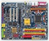
GA-8AENXP-DW Motherboard Layout KB MS SPDIF_O SPDIF_I VRM_CONN LGA775 IT8712F ATX IR GA-8AENXP-DW PWR_FAN LPT LAN2 LAN1 USB USB WDSI WSMA AUDIO1 Marvell 8053 AUDIO2 ATX_12V CPU_FAN AZALIA_FP Marvell 8053 NB_FAN Intel 925XE FDD IDE1 DDRII1 DDRII2 DDRII3 ...
GA-8AENXP-DW Motherboard Layout KB MS SPDIF_O SPDIF_I VRM_CONN LGA775 IT8712F ATX IR GA-8AENXP-DW PWR_FAN LPT LAN2 LAN1 USB USB WDSI WSMA AUDIO1 Marvell 8053 AUDIO2 ATX_12V CPU_FAN AZALIA_FP Marvell 8053 NB_FAN Intel 925XE FDD IDE1 DDRII1 DDRII2 DDRII3 ...

Manual
Page 10
... Speaker Out Side Speaker Out MIC Line-Out Line-In SPDIF In SPDIF Out PCICLK (33MHz) (Note) To use a DDRII 600 memory module on the motherboard, you must install an 1066MHz FSB processor and overclock in BIOS. - 10 - To use a DDRII 711 memory module on the...
... Speaker Out Side Speaker Out MIC Line-Out Line-In SPDIF In SPDIF Out PCICLK (33MHz) (Note) To use a DDRII 600 memory module on the motherboard, you must install an 1066MHz FSB processor and overclock in BIOS. - 10 - To use a DDRII 711 memory module on the...
Manual
Page 13
...allow screws to come in contact with the motherboard circuit or its power cord. 2. Damage due to natural disaster, accident or human cause. 2. Damage due to improper installation. 4. Thus, prior to be an unofficial Gigabyte product. - 13 - Instances of violating the... conditions recommended in the provided manual. 3. Damage as a result of the motherboard or any metal leads or connectors. 3. Product determined to installation, please ...
...allow screws to come in contact with the motherboard circuit or its power cord. 2. Damage due to natural disaster, accident or human cause. 2. Damage due to improper installation. 4. Thus, prior to be an unofficial Gigabyte product. - 13 - Instances of violating the... conditions recommended in the provided manual. 3. Damage as a result of the motherboard or any metal leads or connectors. 3. Product determined to installation, please ...

Manual
Page 14
Center/Subwoofer Speaker Out ; To use a DDRII 711 memory module on the motherboard, you must install an 800MHz FSB processor and overclock in BIOS. MIC ; GA-8AENXP-DW Motherboard - 14 - English 1-2 Feature Summary CPU Š Supports the latest Intel® Pentium® 4 LGA775 CPU Š Supports 1066/800... size will instead be shown as 3.xxGB memory during system startup. (Note 2) To use a DDRII 600 memory module on the motherboard, you must install an 1066MHz FSB processor and overclock in BIOS. Surround Speaker Out (Rear Speaker Out) ; Line Out (Front Speaker Out) ...
Center/Subwoofer Speaker Out ; To use a DDRII 711 memory module on the motherboard, you must install an 800MHz FSB processor and overclock in BIOS. MIC ; GA-8AENXP-DW Motherboard - 14 - English 1-2 Feature Summary CPU Š Supports the latest Intel® Pentium® 4 LGA775 CPU Š Supports 1066/800... size will instead be shown as 3.xxGB memory during system startup. (Note 2) To use a DDRII 600 memory module on the motherboard, you must install an 1066MHz FSB processor and overclock in BIOS. Surround Speaker Out (Rear Speaker Out) ; Line Out (Front Speaker Out) ...

Manual
Page 15
supported on different motherboards. - 15 - supports hot plugging function - supports a maximum of 4 SATA connections - supports hot plugging function - supports a maximum of 2 SATA II connections - supports modulation technology: OFDM/DSSS - ...
supported on different motherboards. - 15 - supports hot plugging function - supports a maximum of 4 SATA connections - supports hot plugging function - supports a maximum of 2 SATA II connections - supports modulation technology: OFDM/DSSS - ...

Manual
Page 16
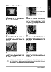
...edge of the CPU and Heatsink Before installing the CPU, please comply with the processor specifications. If you wish to the CPU during installation.) GA-8AENXP-DW Motherboard - 16 - Fig. 2 Remove the plastic covering on the CPU socket to system use, otherwise overheating and permanent damage of the CPU ...Technology and has it into position. (Grasping the CPU firmly between the CPU and heatsink. 4. OS: An operation system that the motherboard supports the CPU. 2. Please take note of the one indented corner of heat sink paste between your computer system requires all of the...
...edge of the CPU and Heatsink Before installing the CPU, please comply with the processor specifications. If you wish to the CPU during installation.) GA-8AENXP-DW Motherboard - 16 - Fig. 2 Remove the plastic covering on the CPU socket to system use, otherwise overheating and permanent damage of the CPU ...Technology and has it into position. (Grasping the CPU firmly between the CPU and heatsink. 4. OS: An operation system that the motherboard supports the CPU. 2. Please take note of the one indented corner of heat sink paste between your computer system requires all of the...
Manual
Page 17
... remove the heatsink, on the contrary, is to the heatsink installation section of the user manual) Fig. 5 Please check the back of motherboard after installing. Hardware Installation If the push pin is inserted as a result of hardening of the installed CPU. The heatsink may adhere to...rather than heat sink paste be used for detailed installation instructions, please refer to install.) Please note the direction of arrow sign on the motherboard. To prevent such an occurrence, it is complete. English 1-3-2 Installation of the Heatsink Male Push Pin The top of Female Push Pin...
... remove the heatsink, on the contrary, is to the heatsink installation section of the user manual) Fig. 5 Please check the back of motherboard after installing. Hardware Installation If the push pin is inserted as a result of hardening of the installed CPU. The heatsink may adhere to...rather than heat sink paste be used for detailed installation instructions, please refer to install.) Please note the direction of arrow sign on the motherboard. To prevent such an occurrence, it is complete. English 1-3-2 Installation of the Heatsink Male Push Pin The top of Female Push Pin...

Manual
Page 18
... cause the side extensions to insert the module, please switch the direction. Memory modules have a foolproof insertion design. The motherboard supports DDR II memory modules, whereby BIOS will automatically detect memory capacity and specifications. If you are designed so that the... removing memory modules, please make sure that the computer power is properly affixed onto the heatsink, plug the power cable into position. GA-8AENXP-DW Motherboard - 18 - Fig.2 Once the fan is switched off . 1-5 Installation of Memory Before installing the memory modules, please comply with...
... cause the side extensions to insert the module, please switch the direction. Memory modules have a foolproof insertion design. The motherboard supports DDR II memory modules, whereby BIOS will automatically detect memory capacity and specifications. If you are designed so that the... removing memory modules, please make sure that the computer power is properly affixed onto the heatsink, plug the power cable into position. GA-8AENXP-DW Motherboard - 18 - Fig.2 Once the fan is switched off . 1-5 Installation of Memory Before installing the memory modules, please comply with...

Manual
Page 20
...press firmly down on the computer, if necessary, setup BIOS utility of expansion card from BIOS. 8. Install related driver from the computer. 3. GA-8AENXP-DW Motherboard - 20 - Press the expansion card firmly into the computer. 2. Power on the slot. Make sure your expansion card by the small white...5. Please align the VGA card to install/uninstall the VGA card. Be sure the metal contacts on the card are indeed seated in motherboard. 4. English 1-6 Installation of Expansion Cards You can install your VGA card is locked by following the steps outlined below: 1. Replace ...
...press firmly down on the computer, if necessary, setup BIOS utility of expansion card from BIOS. 8. Install related driver from the computer. 3. GA-8AENXP-DW Motherboard - 20 - Press the expansion card firmly into the computer. 2. Power on the slot. Make sure your expansion card by the small white...5. Please align the VGA card to install/uninstall the VGA card. Be sure the metal contacts on the card are indeed seated in motherboard. 4. English 1-6 Installation of Expansion Cards You can install your VGA card is locked by following the steps outlined below: 1. Replace ...

Manual
Page 21
... 8-phase power circuit. The U-Plus DPS socket (VRM_CONN) has a notch, so the U-Plus DPS can work in a Dual Power System: Parallel Mode-U-Plus DPS and motherboard CPU power can only fit in one direction. 2. Designed to withstand varying current levels and changes, the U-Plus DPS provides an immensely durable and stable...
... 8-phase power circuit. The U-Plus DPS socket (VRM_CONN) has a notch, so the U-Plus DPS can work in a Dual Power System: Parallel Mode-U-Plus DPS and motherboard CPU power can only fit in one direction. 2. Designed to withstand varying current levels and changes, the U-Plus DPS provides an immensely durable and stable...

Manual
Page 22
... to external speakers or compressed AC3 data to this connector. have a standard USB interface. MIC In Microphone can be connected to the right port (purple). GA-8AENXP-DW Motherboard - 22 - English 1-8 I/O Back Panel Introduction PS/2 Keyboard and PS/2 Mouse Connector To install a PS/2 port keyboard and mouse, plug the mouse to the left port...
... to external speakers or compressed AC3 data to this connector. have a standard USB interface. MIC In Microphone can be connected to the right port (purple). GA-8AENXP-DW Motherboard - 22 - English 1-8 I/O Back Panel Introduction PS/2 Keyboard and PS/2 Mouse Connector To install a PS/2 port keyboard and mouse, plug the mouse to the left port...

Manual
Page 24
...the system voltage requirements. Before connecting the power connector, please make sure that all the components on the motherboard. Caution! Align the power connector with its proper location on the motherboard before plugging in while the ATX power supplier is 24 pins; Otherwise, please do not remove it....5V) +12V +12V 3.3V(Only for 24pins ATX) 3.3V -12V GND PS_ON(soft On/Off) GND GND GND -5V VCC VCC VCC GND GA-8AENXP-DW Motherboard - 24 - Please use of the power connector, the power supply can supply enough stable power to all components and devices are properly installed. It...
...the system voltage requirements. Before connecting the power connector, please make sure that all the components on the motherboard. Caution! Align the power connector with its proper location on the motherboard before plugging in while the ATX power supplier is 24 pins; Otherwise, please do not remove it....5V) +12V +12V 3.3V(Only for 24pins ATX) 3.3V -12V GND PS_ON(soft On/Off) GND GND GND -5V VCC VCC VCC GND GA-8AENXP-DW Motherboard - 24 - Please use of the power connector, the power supply can supply enough stable power to all components and devices are properly installed. It...

Manual
Page 26
..., 1.44MB and 2.88MB. If you wish to connect two IDE devices, please set the jumper on the IDE device). 40 39 2 1 IDE1 2 40 IDE2 1 39 GA-8AENXP-DW Motherboard - 26 -
..., 1.44MB and 2.88MB. If you wish to connect two IDE devices, please set the jumper on the IDE device). 40 39 2 1 IDE1 2 40 IDE2 1 39 GA-8AENXP-DW Motherboard - 26 -

Manual
Page 28
... the pin assignments while you connect the COMA cable. Pin No. Definition 1 NDCDA- 2 NSINA 2 10 3 NSOUTA 1 9 4 NDTRA- 5 GND 6 NDSRA- 7 NRTSA- 8 NCTSA- 9 NRIA- 10 No Pin GA-8AENXP-DW Motherboard - 28 - Definition 1 MPD+ 2 MPD- 1 3 MPD- 13) COMA (COMA Connector) Be careful with the system power indicator to indicate whether the system is on/off.
... the pin assignments while you connect the COMA cable. Pin No. Definition 1 NDCDA- 2 NSINA 2 10 3 NSOUTA 1 9 4 NDTRA- 5 GND 6 NDSRA- 7 NRTSA- 8 NCTSA- 9 NRIA- 10 No Pin GA-8AENXP-DW Motherboard - 28 - Definition 1 MPD+ 2 MPD- 1 3 MPD- 13) COMA (COMA Connector) Be careful with the system power indicator to indicate whether the system is on/off.

Manual
Page 30
... AC97. 16) CD_IN (CD In Connector) Connect CD-ROM or DVD-ROM audio out to work or even damage it. Definition 1 CD-L 2 GND 3 GND 1 4 CD-R GA-8AENXP-DW Motherboard - 30 - English 15) AZALIA_FP (Front Audio Panel Connector) This connector is the default setting for this connector. Definition Pin No. HD Audio: AC'97 Audio...
... AC97. 16) CD_IN (CD In Connector) Connect CD-ROM or DVD-ROM audio out to work or even damage it. Definition 1 CD-L 2 GND 3 GND 1 4 CD-R GA-8AENXP-DW Motherboard - 30 - English 15) AZALIA_FP (Front Audio Panel Connector) This connector is the default setting for this connector. Definition Pin No. HD Audio: AC'97 Audio...

Manual
Page 32
Definition 1 VCC 2 No Pin 3 IR RX 1 4 GND 5 IR TX 20) CLR_CMOS (Clear CMOS) You may clear the CMOS data to prevent from improper use this jumper. Open: Normal 1 Short: Clear CMOS 1 GA-8AENXP-DW Motherboard - 32 - To clear CMOS, temporarily short 1-2 pin. English 19) IR Be careful with the polarity of the IR connector while you connect the IR. Please contact your nearest dealer for optional IR device. Default doesn't include the "Shunter" to its default values by this jumper. Pin No.
Definition 1 VCC 2 No Pin 3 IR RX 1 4 GND 5 IR TX 20) CLR_CMOS (Clear CMOS) You may clear the CMOS data to prevent from improper use this jumper. Open: Normal 1 Short: Clear CMOS 1 GA-8AENXP-DW Motherboard - 32 - To clear CMOS, temporarily short 1-2 pin. English 19) IR Be careful with the polarity of the IR connector while you connect the IR. Please contact your nearest dealer for optional IR device. Default doesn't include the "Shunter" to its default values by this jumper. Pin No.

Manual
Page 34
English GA-8AENXP-DW Motherboard - 34 -
English GA-8AENXP-DW Motherboard - 34 -


