Manual
Page 1
GA-880GMA-UD2H AM3 socket motherboard for AMD Phenom™ II processor/AMD Athlon™ II processor User's Manual Rev. 2002 12ME-880GA2H-2002R
GA-880GMA-UD2H AM3 socket motherboard for AMD Phenom™ II processor/AMD Athlon™ II processor User's Manual Rev. 2002 12ME-880GA2H-2002R
Manual
Page 2
Motherboard GA-880GMA-UD2H Apr. 12, 2010 Motherboard GA-880GMA-UD2H Apr. 12, 2010
Motherboard GA-880GMA-UD2H Apr. 12, 2010 Motherboard GA-880GMA-UD2H Apr. 12, 2010
Manual
Page 3
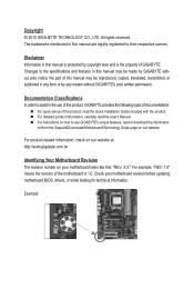
... is protected by copyright laws and is 1.0. For product-related information, check on our website at: http://www.gigabyte.com.tw Identifying Your Motherboard Revision The revision number on how to assist in any means without prior notice. Example: For instructions on your... Copyright © 2010 GIGA-BYTE TECHNOLOGY CO., LTD. Changes to their respective owners. Check your motherboard looks like this manual may be made by any form or by GIGABYTE without GIGABYTE's prior written permission. No part of the product, read the User's Manual. The trademarks mentioned ...
... is protected by copyright laws and is 1.0. For product-related information, check on our website at: http://www.gigabyte.com.tw Identifying Your Motherboard Revision The revision number on how to assist in any means without prior notice. Example: For instructions on your... Copyright © 2010 GIGA-BYTE TECHNOLOGY CO., LTD. Changes to their respective owners. Check your motherboard looks like this manual may be made by any form or by GIGABYTE without GIGABYTE's prior written permission. No part of the product, read the User's Manual. The trademarks mentioned ...
Manual
Page 4
Table of Contents Box Contents...6 Optional Items...6 GA-880GMA-UD2H Motherboard Layout 7 GA-880GMA-UD2H Motherboard Block Diagram 8 Chapter 1 Hardware Installation 9 1-1 Installation Precautions 9 1-2 Product Specifications 10 1-3 Installing the CPU and CPU Cooler 13 1-3-1 Installing the CPU 13 1-3-2 Installing the CPU Cooler ...
Table of Contents Box Contents...6 Optional Items...6 GA-880GMA-UD2H Motherboard Layout 7 GA-880GMA-UD2H Motherboard Block Diagram 8 Chapter 1 Hardware Installation 9 1-1 Installation Precautions 9 1-2 Product Specifications 10 1-3 Installing the CPU and CPU Cooler 13 1-3-1 Installing the CPU 13 1-3-2 Installing the CPU Cooler ...
Manual
Page 6
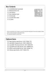
... 12CF1-2SERPW-0*R) S/PDIF In and Out cable (Part No. 12CR1-1SPINO-1*R) COM port cable (Part No. 12CF1-1CM001-3*R) - 6 - Box Contents GA-880GMA-UD2H motherboard Motherboard driver disk User's Manual Quick Installation Guide One IDE cable Two SATA 3Gb/s cables I/O Shield • The box contents above are subject to change ...without notice. • The motherboard image is for reference only and the actual items shall depend on the product package you obtain. The box contents are for reference only....
... 12CF1-2SERPW-0*R) S/PDIF In and Out cable (Part No. 12CR1-1SPINO-1*R) COM port cable (Part No. 12CF1-1CM001-3*R) - 6 - Box Contents GA-880GMA-UD2H motherboard Motherboard driver disk User's Manual Quick Installation Guide One IDE cable Two SATA 3Gb/s cables I/O Shield • The box contents above are subject to change ...without notice. • The motherboard image is for reference only and the actual items shall depend on the product package you obtain. The box contents are for reference only....
Manual
Page 7
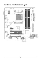
TSB43AB23 CLR_CMOS DDR3_1 DDR3_2 DDR3_3 DDR3_4 IDE AMD SB850 JMicron JMB368 SATA3_3 SATA3_1 BAT SPDIF_IO COM SYS_FAN F_1394 F_USB2 F_USB3 F_USB1 SATA3_4 SATA3_2 SATA3_0 F_PANEL - 7 - GA-880GMA-UD2H Motherboard Layout KB_MS_USB ATX_12V CPU_FAN VGA_DVI Socket AM3 M_BIOS B_BIOS ATX FDD iTE IT8720 HDMI_SPDIF ESATA_1394_USB USB30_LAN NEC D720200F1 F_AUDIO AUDIO PCIEX1 Realtek RTL8111D CD_IN CODEC PCIEX16 PCIEX4 PCI AMD 880G GA-880GMA-UD2H T.I.
TSB43AB23 CLR_CMOS DDR3_1 DDR3_2 DDR3_3 DDR3_4 IDE AMD SB850 JMicron JMB368 SATA3_3 SATA3_1 BAT SPDIF_IO COM SYS_FAN F_1394 F_USB2 F_USB3 F_USB1 SATA3_4 SATA3_2 SATA3_0 F_PANEL - 7 - GA-880GMA-UD2H Motherboard Layout KB_MS_USB ATX_12V CPU_FAN VGA_DVI Socket AM3 M_BIOS B_BIOS ATX FDD iTE IT8720 HDMI_SPDIF ESATA_1394_USB USB30_LAN NEC D720200F1 F_AUDIO AUDIO PCIEX1 Realtek RTL8111D CD_IN CODEC PCIEX16 PCIEX4 PCI AMD 880G GA-880GMA-UD2H T.I.
Manual
Page 8
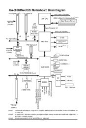
GA-880GMA-UD2H Motherboard Block Diagram 1 PCI Express x16 (Note 1) 1 PCI Express x4 CPU CLK+/- (200 MHz) PCIe CLK (100 MHz) LAN RJ45 AM3 CPU DDR3 1800(O.C.)/1333/1066 ...
GA-880GMA-UD2H Motherboard Block Diagram 1 PCI Express x16 (Note 1) 1 PCI Express x4 CPU CLK+/- (200 MHz) PCIe CLK (100 MHz) LAN RJ45 AM3 CPU DDR3 1800(O.C.)/1333/1066 ...
Manual
Page 9
... 9 - These stickers are required for warranty validation. • Always remove the AC power by unplugging the power cord from the motherboard, make sure the power supply has been turned off. • Before turning on the power, make sure they are uncertain about ... wear an electrostatic discharge (ESD) wrist strap when handling electronic com- Hardware Installation Chapter 1 Hardware Installation 1-1 Installation Precautions The motherboard contains numerous delicate electronic circuits and components which can lead to damage to system components as well as physical harm to the user...
... 9 - These stickers are required for warranty validation. • Always remove the AC power by unplugging the power cord from the motherboard, make sure the power supply has been turned off. • Before turning on the power, make sure they are uncertain about ... wear an electrostatic discharge (ESD) wrist strap when handling electronic com- Hardware Installation Chapter 1 Hardware Installation 1-1 Installation Precautions The motherboard contains numerous delicate electronic circuits and components which can lead to damage to system components as well as physical harm to the user...
Manual
Page 12
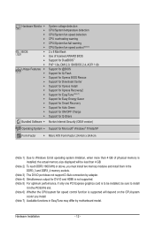
... CPU/system fan speed control function is supported will depend on the CPU/system cooler you install. (Note 7) Available functions in EasyTune may differ by motherboard model. Hardware Installation - 12 -
... CPU/system fan speed control function is supported will depend on the CPU/system cooler you install. (Note 7) Available functions in EasyTune may differ by motherboard model. Hardware Installation - 12 -
Manual
Page 13
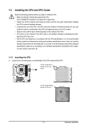
... installing the CPU to prevent hardware damage. • Locate the pin one (denoted by a small triangle) of the CPU. It is not recommended that the motherboard supports the CPU. (Go to GIGABYTE's website for the peripherals.
... installing the CPU to prevent hardware damage. • Locate the pin one (denoted by a small triangle) of the CPU. It is not recommended that the motherboard supports the CPU. (Go to GIGABYTE's website for the peripherals.
Manual
Page 14
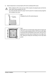
... pins fit perfectly into the CPU socket. Adjust the CPU orientation if this occurs. Follow the steps below to correctly install the CPU into the motherboard CPU socket. • Before installing the CPU, make sure to turn off the computer and unplug the power cord from the power outlet to prevent...
... pins fit perfectly into the CPU socket. Adjust the CPU orientation if this occurs. Follow the steps below to correctly install the CPU into the motherboard CPU socket. • Before installing the CPU, make sure to turn off the computer and unplug the power cord from the power outlet to prevent...
Manual
Page 15
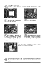
1-3-2 Installing the CPU Cooler Follow the steps below to correctly install the CPU cooler on the CPU. (The following procedure uses the GIGABYTE cooler as the picture above shows) to lock into place. (Refer to your CPU cooler installation manual for instructions on installing the cooler.) Step 5: Finally, ... the installed CPU. On the other side,push straight down on the the CPU cooler clip to hook it to the mounting lug on the motherboard. Use extreme care when removing the CPU cooler because the thermal grease/tape between the CPU cooler and CPU may damage the CPU. - 15 - Step...
1-3-2 Installing the CPU Cooler Follow the steps below to correctly install the CPU cooler on the CPU. (The following procedure uses the GIGABYTE cooler as the picture above shows) to lock into place. (Refer to your CPU cooler installation manual for instructions on installing the cooler.) Step 5: Finally, ... the installed CPU. On the other side,push straight down on the the CPU cooler clip to hook it to the mounting lug on the motherboard. Use extreme care when removing the CPU cooler because the thermal grease/tape between the CPU cooler and CPU may damage the CPU. - 15 - Step...

Manual
Page 16
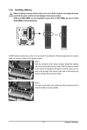
... is installed. 2. If you begin to insert the memory, switch the direction. 1-4-1 Dual Channel Memory Configuration This motherboard provides four DDR3 memory sockets and supports Dual Channel Technology. The four DDR3 memory sockets are unable to install the... memory: • Make sure that the motherboard supports the memory. A memory module can be used and installed in only one DDR3 memory module is ...power cord from the power outlet before installing the memory to GIGABYTE's website for optimum performance.
... is installed. 2. If you begin to insert the memory, switch the direction. 1-4-1 Dual Channel Memory Configuration This motherboard provides four DDR3 memory sockets and supports Dual Channel Technology. The four DDR3 memory sockets are unable to install the... memory: • Make sure that the motherboard supports the memory. A memory module can be used and installed in only one DDR3 memory module is ...power cord from the power outlet before installing the memory to GIGABYTE's website for optimum performance.
Manual
Page 17
Place the memory module on this motherboard. As indicated in the picture on the memory and insert it can only fit in the memory sockets. Follow the steps below to correctly install ...
Place the memory module on this motherboard. As indicated in the picture on the memory and insert it can only fit in the memory sockets. Follow the steps below to correctly install ...
Manual
Page 18
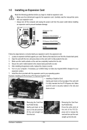
... turn off the computer and unplug the power cord from the power outlet before you begin to install an expansion card: • Make sure the motherboard supports the expansion card. Make sure the card is fully seated in the expansion slot. 1. Make sure the metal contacts on your expansion card in...
... turn off the computer and unplug the power cord from the power outlet before you begin to install an expansion card: • Make sure the motherboard supports the expansion card. Make sure the card is fully seated in the expansion slot. 1. Make sure the metal contacts on your expansion card in...
Manual
Page 19
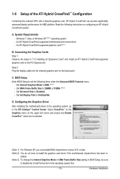
...B. Set Internal Graphics Mode to OnChipVGA. Hardware Installation Set Init Display First to UMA. (Note 3) - Configuring the Graphics Driver After installing the motherboard driver in BIOS Setup, be sure to Disabled. - A. Set UMA Frame Buffer Size to the ATI Catalyst™ Control Center. D. An ... the Graphics Cards Step 1: Observe the steps in - BIOS Setup Enter BIOS Setup to install the graphics card driver if the motherboard chipset driver has been in "1-5 Installing an Expansion Card" and install an ATI Hybrid CrossFireX-supported graphics card on the PCI Express...
...B. Set Internal Graphics Mode to OnChipVGA. Hardware Installation Set Init Display First to UMA. (Note 3) - Configuring the Graphics Driver After installing the motherboard driver in BIOS Setup, be sure to Disabled. - A. Set UMA Frame Buffer Size to the ATI Catalyst™ Control Center. D. An ... the Graphics Cards Step 1: Observe the steps in - BIOS Setup Enter BIOS Setup to install the graphics card driver if the motherboard chipset driver has been in "1-5 Installing an Expansion Card" and install an ATI Hybrid CrossFireX-supported graphics card on the PCI Express...

Manual
Page 21
... 1394 port supports the IEEE 1394a specification, featuring high speed, high bandwidth and hotplug capabilities. Do not rock it straight out from the motherboard. • When removing the cable, pull it side to side to a back panel connector, first remove the cable from your device ...the connector. The table below . • Memory: Two 1 GB DDR3 1066 memory modules with SATA 1.5Gb/s standard. Dual Display Configurations: This motherboard provides three ports for DVI-D and HDMI is compatible with dual channel mode enabled • BIOS Setup: At least 256 MB of the LAN ...
... 1394 port supports the IEEE 1394a specification, featuring high speed, high bandwidth and hotplug capabilities. Do not rock it straight out from the motherboard. • When removing the cable, pull it side to side to a back panel connector, first remove the cable from your device ...the connector. The table below . • Memory: Two 1 GB DDR3 1066 memory modules with SATA 1.5Gb/s standard. Dual Display Configurations: This motherboard provides three ports for DVI-D and HDMI is compatible with dual channel mode enabled • BIOS Setup: At least 256 MB of the LAN ...
Manual
Page 23
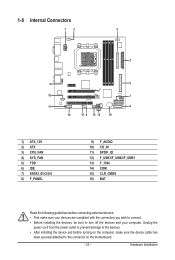
... 9) F_AUDIO 10) CD_IN 11) SPDIF_IO 12) F_USB1/F_USB2/F_USB3 13) F_1394 14) COM 15) CLR_CMOS 16) BAT Read the following guidelines before turning on the motherboard. - 23 - Unplug the power cord from the power outlet to prevent damage to the devices. • After installing the device and before connecting external devices...
... 9) F_AUDIO 10) CD_IN 11) SPDIF_IO 12) F_USB1/F_USB2/F_USB3 13) F_1394 14) COM 15) CLR_CMOS 16) BAT Read the following guidelines before turning on the motherboard. - 23 - Unplug the power cord from the power outlet to prevent damage to the devices. • After installing the device and before connecting external devices...
Manual
Page 24
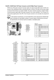
... power connector possesses a foolproof design. Connect the power supply cable to the CPU. If a power supply is turned off and all the components on the motherboard. The 12V power connector mainly supplies power to the power connector in the correct orientation. If the 12V power connector is recommended that a power supply...
... power connector possesses a foolproof design. Connect the power supply cable to the CPU. If a power supply is turned off and all the components on the motherboard. The 12V power connector mainly supplies power to the power connector in the correct orientation. If the 12V power connector is recommended that a power supply...
Manual
Page 25
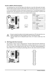
...headers. 5) FDD (Floppy Disk Drive Connector) This connector is recommended that a system fan be installed inside the chassis. 3/4) CPU_FAN/SYS_FAN (Fan Headers) The motherboard has a 4-pin CPU fan header (CPU_FAN) and a 4-pin (SYS_FAN) system fan header. CPU_FAN: Pin No. Overheating may hang. • These fan... headers are : 360 KB, 720 KB, 1.2 MB, 1.44 MB, and 2.88 MB. The motherboard supports CPU fan speed control, which requires the use of the connector and the floppy disk drive cable. Before connecting a floppy disk drive, be ...
...headers. 5) FDD (Floppy Disk Drive Connector) This connector is recommended that a system fan be installed inside the chassis. 3/4) CPU_FAN/SYS_FAN (Fan Headers) The motherboard has a 4-pin CPU fan header (CPU_FAN) and a 4-pin (SYS_FAN) system fan header. CPU_FAN: Pin No. Overheating may hang. • These fan... headers are : 360 KB, 720 KB, 1.2 MB, 1.44 MB, and 2.88 MB. The motherboard supports CPU fan speed control, which requires the use of the connector and the floppy disk drive cable. Before connecting a floppy disk drive, be ...


