Manual
Page 1
GA-880GM-UD2H/ GA-880GM-US2H AM3 socket motherboard for AMD Phenom™ II processor/AMD Athlon™ II processor User's Manual Rev. 1001 12ME-88GMU2H-1001R
GA-880GM-UD2H/ GA-880GM-US2H AM3 socket motherboard for AMD Phenom™ II processor/AMD Athlon™ II processor User's Manual Rev. 1001 12ME-88GMU2H-1001R
Manual
Page 2
Motherboard GA-880GM-UD2H/GA-880GM-US2H Mar. 5, 2010 Motherboard GA-880GM-UD2H/ GA-880GM-US2H Mar. 5, 2010
Motherboard GA-880GM-UD2H/GA-880GM-US2H Mar. 5, 2010 Motherboard GA-880GM-UD2H/ GA-880GM-US2H Mar. 5, 2010
Manual
Page 3
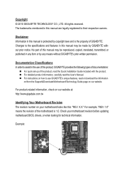
.... For detailed product information, carefully read or download the information on/from the Support&Downloads\Motherboard\Technology Guide page on your motherboard revision before updating motherboard BIOS, drivers, or when looking for technical information. Example: The trademarks mentioned in this product, GIGABYTE provides the following types of documentations: For quick set-up of the...
.... For detailed product information, carefully read or download the information on/from the Support&Downloads\Motherboard\Technology Guide page on your motherboard revision before updating motherboard BIOS, drivers, or when looking for technical information. Example: The trademarks mentioned in this product, GIGABYTE provides the following types of documentations: For quick set-up of the...
Manual
Page 4
Table of Contents Box Contents...6 Optional Items...6 GA-880GM-UD2H/GA-880GM-US2H Motherboard Layout 7 GA-880GM-UD2H/GA-880GM-US2H Motherboard Block Diagram 8 Chapter 1 Hardware Installation 9 1-1 Installation Precautions 9 1-2 Product Specifications 10 1-3 Installing the CPU and CPU Cooler 13 1-3-1 Installing the CPU 13 1-3-2 Installing the CPU Cooler ...
Table of Contents Box Contents...6 Optional Items...6 GA-880GM-UD2H/GA-880GM-US2H Motherboard Layout 7 GA-880GM-UD2H/GA-880GM-US2H Motherboard Block Diagram 8 Chapter 1 Hardware Installation 9 1-1 Installation Precautions 9 1-2 Product Specifications 10 1-3 Installing the CPU and CPU Cooler 13 1-3-1 Installing the CPU 13 1-3-2 Installing the CPU Cooler ...
Manual
Page 6
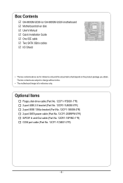
Box Contents GA-880GM-UD2H or GA-880GM-US2H motherboard Motherboard driver disk User's Manual Quick Installation Guide One IDE cable Two SATA 3Gb/s cables I/O Shield • The box contents above are subject to change without notice. • The motherboard image is for reference only and the actual items shall depend on the product package you obtain. Optional Items...
Box Contents GA-880GM-UD2H or GA-880GM-US2H motherboard Motherboard driver disk User's Manual Quick Installation Guide One IDE cable Two SATA 3Gb/s cables I/O Shield • The box contents above are subject to change without notice. • The motherboard image is for reference only and the actual items shall depend on the product package you obtain. Optional Items...
Manual
Page 7
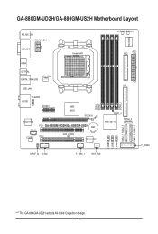
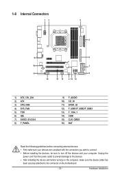
GA-880GM-UD2H/GA-880GM-US2H Motherboard Layout KB_MS_USB ATX_12V_2X4 VGA_DVI Socket AM3 M_BIOS B_BIOS ATX FDD iTE IT8720 HDMI OPTICAL ESATA_1394_USB CPU_FAN USB_LAN F_AUDIO AUDIO PCIEX1 AMD 880G PCIEX16 RTL8111D CD_IN CODEC PCI1 GA-880GM-UD2H/GA-880GM-US2H BAT CLR_CMOS PCI2 TSB43AB23 DDR3_1 DDR3_2 DDR3_4 IDE DDR3_3 AMD SB710 SATA2_4 SPDIF_IO COM F_1394_1 SYS_FAN F_USB1 F_USB2 F_USB3 SATA2_1 SATA2_3 SATA2_0 SATA2_2 F_PANEL "*" The GA-880GM-UD2H adopts All-Solid Capacitor design. - 7 -
GA-880GM-UD2H/GA-880GM-US2H Motherboard Layout KB_MS_USB ATX_12V_2X4 VGA_DVI Socket AM3 M_BIOS B_BIOS ATX FDD iTE IT8720 HDMI OPTICAL ESATA_1394_USB CPU_FAN USB_LAN F_AUDIO AUDIO PCIEX1 AMD 880G PCIEX16 RTL8111D CD_IN CODEC PCI1 GA-880GM-UD2H/GA-880GM-US2H BAT CLR_CMOS PCI2 TSB43AB23 DDR3_1 DDR3_2 DDR3_4 IDE DDR3_3 AMD SB710 SATA2_4 SPDIF_IO COM F_1394_1 SYS_FAN F_USB1 F_USB2 F_USB3 SATA2_1 SATA2_3 SATA2_0 SATA2_2 F_PANEL "*" The GA-880GM-UD2H adopts All-Solid Capacitor design. - 7 -
Manual
Page 8
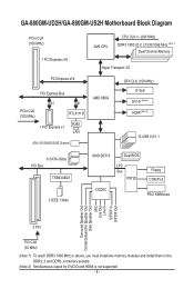
GA-880GM-UD2H/GA-880GM-US2H Motherboard Block Diagram PCIe CLK (100 MHz) 1 PCI Express x16 PCI Express x16 PCI Express Bus x1 x1 PCIe CLK (100 MHz) RTL8111D RJ45 1 PCI Express ...
GA-880GM-UD2H/GA-880GM-US2H Motherboard Block Diagram PCIe CLK (100 MHz) 1 PCI Express x16 PCI Express x16 PCI Express Bus x1 x1 PCIe CLK (100 MHz) RTL8111D RJ45 1 PCI Express ...
Manual
Page 9
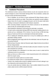
...the product, please consult a certified computer technician. - 9 - These stickers are connected tightly and securely. • When handling the motherboard, avoid touching any installation steps or have it on top of an antistatic pad or within the computer casing. • Do not ...warranty validation. • Always remove the AC power by your dealer. Hardware Installation Chapter 1 Hardware Installation 1-1 Installation Precautions The motherboard contains numerous delicate electronic circuits and components which can lead to damage to system components as well as physical harm to the ...
...the product, please consult a certified computer technician. - 9 - These stickers are connected tightly and securely. • When handling the motherboard, avoid touching any installation steps or have it on top of an antistatic pad or within the computer casing. • Do not ...warranty validation. • Always remove the AC power by your dealer. Hardware Installation Chapter 1 Hardware Installation 1-1 Installation Precautions The motherboard contains numerous delicate electronic circuits and components which can lead to damage to system components as well as physical harm to the ...
Manual
Page 12
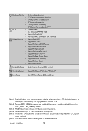
... CPU/system fan speed control function is supported will depend on the CPU/system cooler you install. (Note 6) Available functions in EasyTune may differ by motherboard model.
... CPU/system fan speed control function is supported will depend on the CPU/system cooler you install. (Note 6) Available functions in EasyTune may differ by motherboard model.
Manual
Page 13
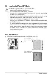
... that the system bus frequency be inserted if oriented incorrectly. (Or you begin to install the CPU: • Make sure that the motherboard supports the CPU. (Go to GIGABYTE's website for the peripherals. Locate the pin one of the Socket AM3 Socket A Small Triangle Marking Denotes CPU Pin One AM3 CPU - 13...
... that the system bus frequency be inserted if oriented incorrectly. (Or you begin to install the CPU: • Make sure that the motherboard supports the CPU. (Go to GIGABYTE's website for the peripherals. Locate the pin one of the Socket AM3 Socket A Small Triangle Marking Denotes CPU Pin One AM3 CPU - 13...
Manual
Page 14
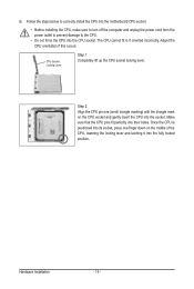
... Locking Lever Step 1: Completely lift up the CPU socket locking lever. Hardware Installation - 14 - Follow the steps below to correctly install the CPU into the motherboard CPU socket. • Before installing the CPU, make sure to turn off the computer and unplug the power cord from the power outlet to prevent...
... Locking Lever Step 1: Completely lift up the CPU socket locking lever. Hardware Installation - 14 - Follow the steps below to correctly install the CPU into the motherboard CPU socket. • Before installing the CPU, make sure to turn off the computer and unplug the power cord from the power outlet to prevent...
Manual
Page 15
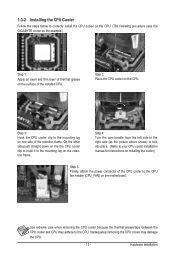
Step 3: Hook the CPU cooler clip to correctly install the CPU cooler on the CPU. (The following procedure uses the GIGABYTE cooler as the picture above shows) to lock into place. (Refer to your CPU cooler installation manual for instructions on installing the cooler.) Step 5: Finally, ...attach the power connector of the CPU cooler to the CPU fan header (CPU_FAN) on the CPU. Step 2: Place the CPU cooler on the motherboard. 1-3-2 Installing the CPU Cooler Follow the steps below to the mounting lug on one side of the retention frame. On the other side,push straight...
Step 3: Hook the CPU cooler clip to correctly install the CPU cooler on the CPU. (The following procedure uses the GIGABYTE cooler as the picture above shows) to lock into place. (Refer to your CPU cooler installation manual for instructions on installing the cooler.) Step 5: Finally, ...attach the power connector of the CPU cooler to the CPU fan header (CPU_FAN) on the CPU. Step 2: Place the CPU cooler on the motherboard. 1-3-2 Installing the CPU Cooler Follow the steps below to the mounting lug on one side of the retention frame. On the other side,push straight...
Manual
Page 16
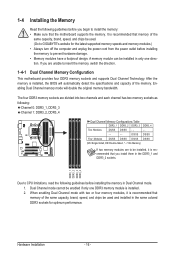
... to be installed, it is recommended that memory of the same capacity, brand, speed, and chips be used . (Go to GIGABYTE's website for optimum performance. When enabling Dual Channel mode with two or four memory modules, it is recommended that you install them ...Dual Channel mode. 1. DDR3_1 DDR3_2 DDR3_3 DDR3_4 Due to insert the memory, switch the direction. 1-4-1 Dual Channel Memory Configuration This motherboard provides four DDR3 memory sockets and supports Dual Channel Technology. Enabling Dual Channel memory mode will automatically detect the specifications and capacity of...
... to be installed, it is recommended that memory of the same capacity, brand, speed, and chips be used . (Go to GIGABYTE's website for optimum performance. When enabling Dual Channel mode with two or four memory modules, it is recommended that you install them ...Dual Channel mode. 1. DDR3_1 DDR3_2 DDR3_3 DDR3_4 Due to insert the memory, switch the direction. 1-4-1 Dual Channel Memory Configuration This motherboard provides four DDR3 memory sockets and supports Dual Channel Technology. Enabling Dual Channel memory mode will automatically detect the specifications and capacity of...
Manual
Page 17
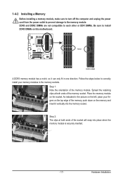
... steps below to the memory module. Step 1: Note the orientation of the socket will snap into the memory socket. Place the memory module on this motherboard. 1-4-2 Installing a Memory Before installing a memory module, make sure to turn off the computer and unplug the power cord from the power outlet to prevent damage...
... steps below to the memory module. Step 1: Note the orientation of the socket will snap into the memory socket. Place the memory module on this motherboard. 1-4-2 Installing a Memory Before installing a memory module, make sure to turn off the computer and unplug the power cord from the power outlet to prevent damage...
Manual
Page 18
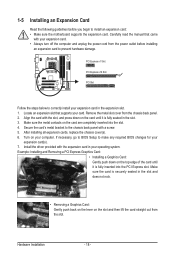
... turn off the computer and unplug the power cord from the power outlet before you begin to install an expansion card: • Make sure the motherboard supports the expansion card. Turn on the card are completely inserted into the PCI Express slot. If necessary, go to BIOS Setup to the chassis...
... turn off the computer and unplug the power cord from the power outlet before you begin to install an expansion card: • Make sure the motherboard supports the expansion card. Turn on the card are completely inserted into the PCI Express slot. If necessary, go to BIOS Setup to the chassis...
Manual
Page 19
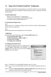
...Set Init Display First to 256MB or 512MB. (Note 3) - D. System Requirements - Configuring the Graphics Driver After installing the motherboard driver in "1-5 Installing an Expansion Card" and install an ATI Hybrid CrossFireX-supported graphics card on the back panel. An ATI Hybrid... CrossFireX-supported motherboard and correct driver - Connecting the Graphics Cards Step 1: Observe the steps in the operating system, go to disable the CrossFire...
...Set Init Display First to 256MB or 512MB. (Note 3) - D. System Requirements - Configuring the Graphics Driver After installing the motherboard driver in "1-5 Installing an Expansion Card" and install an ATI Hybrid CrossFireX-supported graphics card on the back panel. An ATI Hybrid... CrossFireX-supported motherboard and correct driver - Connecting the Graphics Cards Step 1: Observe the steps in the operating system, go to disable the CrossFire...
Manual
Page 21
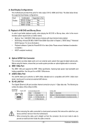
... monitor(s) Optical S/PDIF Out Connector This connector provides digital audio out to an external audio system that your device and then remove it from the motherboard. • When removing the cable, pull it side to side to a back panel connector, first remove the cable from your audio system provides an optical...: DVI-D, HDMI and D-Sub. Hardware Installation Dual Display Combination DVI-D + D-Sub DVI-D + HDMI HDMI + D-Sub Supported or Not Yes No Yes B. Dual Display Configurations: This motherboard provides three ports for an IEEE 1394a device.
... monitor(s) Optical S/PDIF Out Connector This connector provides digital audio out to an external audio system that your device and then remove it from the motherboard. • When removing the cable, pull it side to side to a back panel connector, first remove the cable from your audio system provides an optical...: DVI-D, HDMI and D-Sub. Hardware Installation Dual Display Combination DVI-D + D-Sub DVI-D + HDMI HDMI + D-Sub Supported or Not Yes No Yes B. Dual Display Configurations: This motherboard provides three ports for an IEEE 1394a device.
Manual
Page 23
..., make sure your devices are compliant with the connectors you wish to connect. • Before installing the devices, be sure to the connector on the motherboard. - 23 - Hardware Installation Unplug the power cord from the power outlet to prevent damage to the devices. • After installing the device and before connecting...
..., make sure your devices are compliant with the connectors you wish to connect. • Before installing the devices, be sure to the connector on the motherboard. - 23 - Hardware Installation Unplug the power cord from the power outlet to prevent damage to the devices. • After installing the device and before connecting...
Manual
Page 24
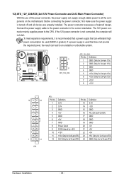
... power connector, first make sure the power supply is used (500W or greater). If a power supply is turned off and all the components on the motherboard. The power connector possesses a foolproof design.
... power connector, first make sure the power supply is used (500W or greater). If a power supply is turned off and all the components on the motherboard. The power connector possesses a foolproof design.
Manual
Page 25
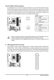
... fan speed control design. Hardware Installation When connecting a fan cable, be sure to connect it is the ground wire). The motherboard supports CPU fan speed control, which requires the use of floppy disk drives supported are not configuration jumper blocks. For purchasing the optional... floppy disk drive cable, please contact the local dealer. 34 33 2 1 - 25 - 3/4) CPU_FAN/SYS_FAN (Fan Headers) The motherboard has a 4-pin CPU fan header (CPU_FAN) and a 4-pin (SYS_FAN) system fan header. For optimum heat dissipation, it in damage to prevent your...
... fan speed control design. Hardware Installation When connecting a fan cable, be sure to connect it is the ground wire). The motherboard supports CPU fan speed control, which requires the use of floppy disk drives supported are not configuration jumper blocks. For purchasing the optional... floppy disk drive cable, please contact the local dealer. 34 33 2 1 - 25 - 3/4) CPU_FAN/SYS_FAN (Fan Headers) The motherboard has a 4-pin CPU fan header (CPU_FAN) and a 4-pin (SYS_FAN) system fan header. For optimum heat dissipation, it in damage to prevent your...


