User Manual
Page 4
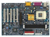
... 8 GA-7VTXE/GA-7VTXH Motherboard Layout 10 Chapter 2 Hardware Installation Process 11 Step 1: Install the Central Processing Unit (CPU 12 Step1-1: CPU Speed Setup 12 Step1-2: CPU Installation 13 Step1-3:CPU Heat Sink Installation 14 Step 2: Install memory modules 15 Step 3: Install expension cards 17 Step 4: Connect ribbon cables, cabinet wires, and power supply 18 Step4-1:I/O Back Panel Introduction 18 Step4-2: Connectors Introduction 20 Chapter 3 BIOS Setup 24 The Main Menu (For example: BIOS Ver. :F1 25 Standard CMOS Features 27 BIOS Features Setup...
... 8 GA-7VTXE/GA-7VTXH Motherboard Layout 10 Chapter 2 Hardware Installation Process 11 Step 1: Install the Central Processing Unit (CPU 12 Step1-1: CPU Speed Setup 12 Step1-2: CPU Installation 13 Step1-3:CPU Heat Sink Installation 14 Step 2: Install memory modules 15 Step 3: Install expension cards 17 Step 4: Connect ribbon cables, cabinet wires, and power supply 18 Step4-1:I/O Back Panel Introduction 18 Step4-2: Connectors Introduction 20 Chapter 3 BIOS Setup 24 The Main Menu (For example: BIOS Ver. :F1 25 Standard CMOS Features 27 BIOS Features Setup...
User Manual
Page 8
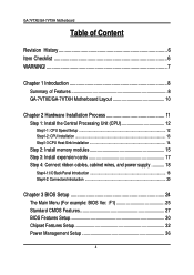
... 4 ATAPI devices Supports PIO mode3,4 (/ATA66/ATA100) IDE & ATAPI CD-ROM 1 Floppy port supports 2 FDD with 360K, 720K,1.2M, 1.44M and 2.88M bytes. 1 Parallel port supports Normal/EPP/ECP mode 1 Serial port (COMA & COMB) 4 USB ports (Rear USB x 2, Front USB x 2) 1 IrDA connector for IR CPU/System Fan Revolution detect CPU/System temperature detect System Voltage Detect to be continued...... 8 GA-7VTXE/GA-7VTXH Motherboard Chapter 1 Introduction Summary of Features Form Factor Motherboard CPU Chipset Memory I/O Control Slots On-Board IDE On-Board Peripherals Hardware Monitor 30...
... 4 ATAPI devices Supports PIO mode3,4 (/ATA66/ATA100) IDE & ATAPI CD-ROM 1 Floppy port supports 2 FDD with 360K, 720K,1.2M, 1.44M and 2.88M bytes. 1 Parallel port supports Normal/EPP/ECP mode 1 Serial port (COMA & COMB) 4 USB ports (Rear USB x 2, Front USB x 2) 1 IrDA connector for IR CPU/System Fan Revolution detect CPU/System temperature detect System Voltage Detect to be continued...... 8 GA-7VTXE/GA-7VTXH Motherboard Chapter 1 Introduction Summary of Features Form Factor Motherboard CPU Chipset Memory I/O Control Slots On-Board IDE On-Board Peripherals Hardware Monitor 30...

User Manual
Page 9
... Port Build in accordance with your system can run under these specific bus frequencies are not the standard specifications for CPU, chipset and most of the peripherals. "**" Only for GA-7VTXH. We don't recommend you to set the CPU host frequency in RTL8100L Chipset* PS/2 Keyboard interface and PS/2 Mouse interace Licensed AMI BIOS, 2M bit Flash ROM Support Dual BIOS STR(Suspend-To-RAM) Wake on LAN** AC Recovery USB KB/Mouse wake up from S3 Supports...
... Port Build in accordance with your system can run under these specific bus frequencies are not the standard specifications for CPU, chipset and most of the peripherals. "**" Only for GA-7VTXH. We don't recommend you to set the CPU host frequency in RTL8100L Chipset* PS/2 Keyboard interface and PS/2 Mouse interace Licensed AMI BIOS, 2M bit Flash ROM Support Dual BIOS STR(Suspend-To-RAM) Wake on LAN** AC Recovery USB KB/Mouse wake up from S3 Supports...
User Manual
Page 12
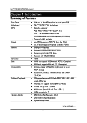
CK_RATIO* RATIO 12 AUTO(Default) X X 5x OO 5.5x XO 6x OX 6.5x XX 7x OO 7.5x XO 8x OX 8.5x XX 9x OO 9.5x XO 10x OX 10.5x XX ... X OO X OO X ON 1 2345 CLK_JP CPU AGP PCI 1 100 66 33 2-3 close 1 133 66 33 1-2 close The system bus frequency can be switched at 100/ 133MHz by CK_RATIO and refer to below table. GA-7VTXE/GA-7VTXH Motherboard Step 1: Install the Central Processing Unit (CPU) Step1-1: CPU Speed Setup The clock ratio can be switched by adjusting system jumper (CLK_JP). (The internal frequency depend on CPU.) "*" CK_RATIO only for GA-7VTXH. 12
CK_RATIO* RATIO 12 AUTO(Default) X X 5x OO 5.5x XO 6x OX 6.5x XX 7x OO 7.5x XO 8x OX 8.5x XX 9x OO 9.5x XO 10x OX 10.5x XX ... X OO X OO X ON 1 2345 CLK_JP CPU AGP PCI 1 100 66 33 2-3 close 1 133 66 33 1-2 close The system bus frequency can be switched at 100/ 133MHz by CK_RATIO and refer to below table. GA-7VTXE/GA-7VTXH Motherboard Step 1: Install the Central Processing Unit (CPU) Step1-1: CPU Speed Setup The clock ratio can be switched by adjusting system jumper (CLK_JP). (The internal frequency depend on CPU.) "*" CK_RATIO only for GA-7VTXH. 12
User Manual
Page 19
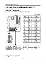
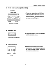
... (15 pin Female) This connector supports joystick, MIDI keyboard and other relate audio devices. Audio Connectors Line Out MIC In Line In After install onboard audio driver, you may connect speaker to Line Out jack, micro phone to Line-In jack. 19 Device like CD-ROM , walkman etc can be connected to MIC In jack. Hardware Installation Process Parallel Port , Serial Ports (COMA / COMB) Parallel Port (25 pin Female) This connector supports 2 standard COM ports ,1 Parallel port .
... (15 pin Female) This connector supports joystick, MIDI keyboard and other relate audio devices. Audio Connectors Line Out MIC In Line In After install onboard audio driver, you may connect speaker to Line Out jack, micro phone to Line-In jack. 19 Device like CD-ROM , walkman etc can be connected to MIC In jack. Hardware Installation Process Parallel Port , Serial Ports (COMA / COMB) Parallel Port (25 pin Female) This connector supports 2 standard COM ports ,1 Parallel port .
User Manual
Page 26
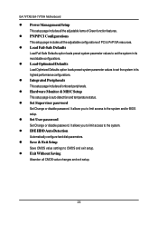
... items of PCI & PnP ISA resources. Set Supervisor password Set Change or disable password. Save & Exit Setup Save CMOS value settings to the system. Exit Without Saving Abandon all onboard peripherals. Load Optimized Defaults Load Optimized Defaults option loads preset system parameter values to set the system in its highest performance configurations. Integrated Peripherals This setup page includes all CMOS value changes and exit setup. 26 IDE HDD Auto Detection Automatically configure hard disk parameters. Load Fail-Safe Defaults Load Fail-Safe Defaults option loads preset...
... items of PCI & PnP ISA resources. Set Supervisor password Set Change or disable password. Save & Exit Setup Save CMOS value settings to the system. Exit Without Saving Abandon all onboard peripherals. Load Optimized Defaults Load Optimized Defaults option loads preset system parameter values to set the system in its highest performance configurations. Integrated Peripherals This setup page includes all CMOS value changes and exit setup. 26 IDE HDD Auto Detection Automatically configure hard disk parameters. Load Fail-Safe Defaults Load Fail-Safe Defaults option loads preset...
User Manual
Page 28
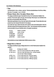
...; There are two types: auto type, and manual type. The hard disk will not work properly if you select User Type, related information will automatically detect HDD type. None No floppy drive installed 360K, 5.25 in. 5.25 inch PC-type standard drive; 360K byte capacity. 1.2M, 5.25 in. 5.25 inch AT-type high-density drive; 1.2M byte capacity (3.5 inch when 3 Mode is calculated base on the 24-hour militarytime clock. Primary Master...
...; There are two types: auto type, and manual type. The hard disk will not work properly if you select User Type, related information will automatically detect HDD type. None No floppy drive installed 360K, 5.25 in. 5.25 inch PC-type standard drive; 360K byte capacity. 1.2M, 5.25 in. 5.25 inch AT-type high-density drive; 1.2M byte capacity (3.5 inch when 3 Mode is calculated base on the 24-hour militarytime clock. Primary Master...
User Manual
Page 30
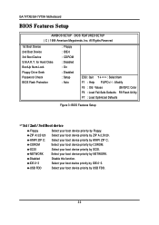
... Hard Disks BootUp Num-Lock Floppy Drive Seek Password Check BIOS Flash Protection : Floppy : IDE-0 : CDROM : Disabled : On : Disabled : Setup : Auto ESC: Quit : Select Item F1 : Help PU/PD+/-/ : Modify F5 : Old Values (Shift)F2: Color F6 : Load Fail-Safe Defaults F8:Flash Utility F7 : Load Optimized Defaults Figure 3: BIOS Features Setup 1st / 2nd / 3rd Boot device Floppy Select your boot device priority by Floppy. CDROM Select your boot device priority by CDROM. USB FDD Select your boot device priority by USB FDD. 30 NETWORK...
... Hard Disks BootUp Num-Lock Floppy Drive Seek Password Check BIOS Flash Protection : Floppy : IDE-0 : CDROM : Disabled : On : Disabled : Setup : Auto ESC: Quit : Select Item F1 : Help PU/PD+/-/ : Modify F5 : Old Values (Shift)F2: Color F6 : Load Fail-Safe Defaults F8:Flash Utility F7 : Load Optimized Defaults Figure 3: BIOS Features Setup 1st / 2nd / 3rd Boot device Floppy Select your boot device priority by Floppy. CDROM Select your boot device priority by CDROM. USB FDD Select your boot device priority by USB FDD. 30 NETWORK...
User Manual
Page 32
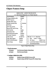
... :Disabled PCI Delay Transaction :Enabled USB Controller :All USB Port ESC: Quit : Select Item USB Legacy Support :Disabled F1 : Help PU/PD+/-/ : Modify USB Port 64/60 Emulation :Disabled F5 : Old Values (Shift)F2: Color VCore Voltage :Normal F6 : Load Fail-Safe Defaults F8:Flash Utility F7 : Load Optimized Defaults Figure 4: Chipset Features Setup Top Performance Disabled Top Performance Disabled. (Default Value) Enabled Top Performance Enabled. Enabled Enabled Configure SDRAM Timing by SPD. Driving :Auto Manual AGP Comp. Configure SDRAM by SPD Disabled...
... :Disabled PCI Delay Transaction :Enabled USB Controller :All USB Port ESC: Quit : Select Item USB Legacy Support :Disabled F1 : Help PU/PD+/-/ : Modify USB Port 64/60 Emulation :Disabled F5 : Old Values (Shift)F2: Color VCore Voltage :Normal F6 : Load Fail-Safe Defaults F8:Flash Utility F7 : Load Optimized Defaults Figure 4: Chipset Features Setup Top Performance Disabled Top Performance Disabled. (Default Value) Enabled Top Performance Enabled. Enabled Enabled Configure SDRAM Timing by SPD. Driving :Auto Manual AGP Comp. Configure SDRAM by SPD Disabled...
User Manual
Page 43
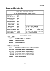
...FDC :Auto OnBoard Serial Port 1 :Auto OnBoard Serial Port 2 :Auto Serial Port2 Mode :Normal OnBoard Parallel Port :Auto Parallel Port Mode :ECP Parallel Port IRQ :Auto Parallel Port DMA :Auto ESC: Quit : Select Item OnBoard IDE :Both F1 : Help PU/PD+/-/ : Modify OnBoard MC'97 Modem :Auto F5 : Old Values (Shift)F2: Color OnBoard Creative Sound :Enabled F6 : Load Fail-Safe Defaults F8:Flash Utility OnBoard LAN Chip :Enabled F7 : Load Optimized Defaults Figure 9: Integrated Peripherals On Board FDC Auto Set On Board FDC is 2E8. Disabled Disabled On Board FDC Enabled...
...FDC :Auto OnBoard Serial Port 1 :Auto OnBoard Serial Port 2 :Auto Serial Port2 Mode :Normal OnBoard Parallel Port :Auto Parallel Port Mode :ECP Parallel Port IRQ :Auto Parallel Port DMA :Auto ESC: Quit : Select Item OnBoard IDE :Both F1 : Help PU/PD+/-/ : Modify OnBoard MC'97 Modem :Auto F5 : Old Values (Shift)F2: Color OnBoard Creative Sound :Enabled F6 : Load Fail-Safe Defaults F8:Flash Utility OnBoard LAN Chip :Enabled F7 : Load Optimized Defaults Figure 9: Integrated Peripherals On Board FDC Auto Set On Board FDC is 2E8. Disabled Disabled On Board FDC Enabled...
User Manual
Page 45
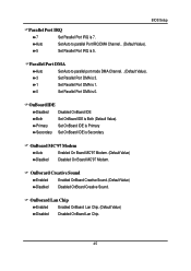
... Secondary Set OnBoard IDE is Both (Default Value). Parallel Port DMA Auto Set Auto to parallel Port IRQ DMA Channel. . (Default Value). 5 Set Parallel Port IRQ is 5. OnBorard Creative Sound Enabled Enabled OnBoard Creative Sound. (Default Value) Disabled Disabled OnBoard Creative Sound. BIOS Setup Parallel Port IRQ 7 Set Parallel Port IRQ is 0. Auto Set Auto to parallel port mode DMA Channel. . (Default Value). 3 Set Parallel Port DMA is 3. 1 Set Parallel Port DMA is 1. 0 Set Parallel Port DMA is 7. OnBorard Lan Chip Enabled Enabled OnBoard Lan Chip. (Default...
... Secondary Set OnBoard IDE is Both (Default Value). Parallel Port DMA Auto Set Auto to parallel Port IRQ DMA Channel. . (Default Value). 5 Set Parallel Port IRQ is 5. OnBorard Creative Sound Enabled Enabled OnBoard Creative Sound. (Default Value) Disabled Disabled OnBoard Creative Sound. BIOS Setup Parallel Port IRQ 7 Set Parallel Port IRQ is 0. Auto Set Auto to parallel port mode DMA Channel. . (Default Value). 3 Set Parallel Port DMA is 3. 1 Set Parallel Port DMA is 1. 0 Set Parallel Port DMA is 7. OnBorard Lan Chip Enabled Enabled OnBoard Lan Chip. (Default...
User Manual
Page 47
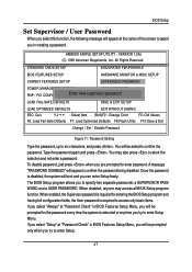
... MONITOR & MISC SETUP CHIPSET FEATURES SETUP SUPERVISOR PASSWORD POWER MANAGEMENT SETUP USER PASSWORD PNP / PCI CONFIGURATIONEnter new supervisoIDrEpHasDsDwAoUrTdO: DETECTION LOAD FAIL-SAFE DEFAULTS SAVE & EXIT SETUP LOAD OPTIMIZED DEFAULTS EXIT WITHOUT SAVING ESC: Quit : Select Item (Shift)F2 : Change Color F5: Old Values F6: Load Fail-Safe Defaults F7: Load Optimized Defaults F8:Flash Utility F10:Save & Exit Change / Set / Disable Password Figure 11: Password Setting Type the password, up to enter password. Type the password again and press . You may access all BIOS Setup...
... MONITOR & MISC SETUP CHIPSET FEATURES SETUP SUPERVISOR PASSWORD POWER MANAGEMENT SETUP USER PASSWORD PNP / PCI CONFIGURATIONEnter new supervisoIDrEpHasDsDwAoUrTdO: DETECTION LOAD FAIL-SAFE DEFAULTS SAVE & EXIT SETUP LOAD OPTIMIZED DEFAULTS EXIT WITHOUT SAVING ESC: Quit : Select Item (Shift)F2 : Change Color F5: Old Values F6: Load Fail-Safe Defaults F7: Load Optimized Defaults F8:Flash Utility F10:Save & Exit Change / Set / Disable Password Figure 11: Password Setting Type the password, up to enter password. Type the password again and press . You may access all BIOS Setup...
User Manual
Page 53
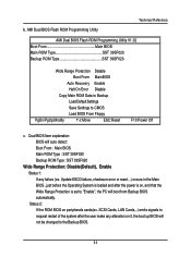
... Backup BIOS. 53 Update ESCD failure, checksum error or reset...) occurs in the Main BIOS , just before the Operating System is set to CMOS Load BIOS From Floppy PgDn/PgUp:Modify :Move ESC:Reset F10:Power Off c. AMI Dual BIOS Flash ROM Programming Utility Technical Reference AMI Dual BIOS Flash ROM Programming Utility V1.02 Boot From Main BIOS Main ROM Type SST 39SF020 Backup ROM Type SST 39SF020 Wide Range Protection Disable Boot From MainBIOS Auto Recovery Enable Halt On Error Disable Copy Main ROM Data to Backup Load Default Settings Save Settings to "Enable...
... Backup BIOS. 53 Update ESCD failure, checksum error or reset...) occurs in the Main BIOS , just before the Operating System is set to CMOS Load BIOS From Floppy PgDn/PgUp:Modify :Move ESC:Reset F10:Power Off c. AMI Dual BIOS Flash ROM Programming Utility Technical Reference AMI Dual BIOS Flash ROM Programming Utility V1.02 Boot From Main BIOS Main ROM Type SST 39SF020 Backup ROM Type SST 39SF020 Wide Range Protection Disable Boot From MainBIOS Auto Recovery Enable Halt On Error Disable Copy Main ROM Data to Backup Load Default Settings Save Settings to "Enable...
User Manual
Page 54
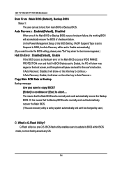
... Power Management Setup of the Main BIOS or Backup BIOS occurs checksum failure, the working BIOS will show mes sages on the boot screen, and the system will pause and wait for the user's instruction. Auto Recovery : Enabled(Default), Disabled When one of the BIOS Setting, if ACPI Suspend Type is set by system automatically and can set to update its BIOS within BIOS mode, no more fooling around any OS. 54 GA-7VTXE/GA-7VTXH Motherboard Boot From : Main BIOS (Default), Backup BIOS Status 1: The user...
... Power Management Setup of the Main BIOS or Backup BIOS occurs checksum failure, the working BIOS will show mes sages on the boot screen, and the system will pause and wait for the user's instruction. Auto Recovery : Enabled(Default), Disabled When one of the BIOS Setting, if ACPI Suspend Type is set by system automatically and can set to update its BIOS within BIOS mode, no more fooling around any OS. 54 GA-7VTXE/GA-7VTXH Motherboard Boot From : Main BIOS (Default), Backup BIOS Status 1: The user...
User Manual
Page 57
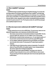
... by BIOS failures. 57 Answer: DualBIOS technology is updated regularly. II. If a user mistakenly updates their mainboard with DualBIOSTM technology? If a user changes peripherals often, there is a slight chance of this technology is pressed during system boot up, and/or loss BIOS data due to the flash ROM. This new technology will be corrupted if a power loss/surge occurs, or if a user resets the system, or if the power button is...
... by BIOS failures. 57 Answer: DualBIOS technology is updated regularly. II. If a user mistakenly updates their mainboard with DualBIOSTM technology? If a user changes peripherals often, there is a slight chance of this technology is pressed during system boot up, and/or loss BIOS data due to the flash ROM. This new technology will be corrupted if a power loss/surge occurs, or if a user resets the system, or if the power button is...
User Manual
Page 64
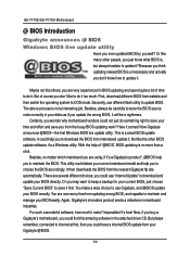
... you could use different flash utility to use Gigabyte, and @BIOS update your Gigabyte @BIOS. 64 you to download and update your time and effort and save it . First, download different BIOS from the nearest Gigabyte ftp site automatically. This utility could detect your BIOS easily. Secondly, use "Internet Update" to download the BIOS from your BIOS smartly. This is not a interesting job. GA-7VTXE/GA-7VTXH Motherboard @ BIOS Introduction Gigabyte announces @ BIOS Windows BIOS live update utility. Not like many other BIOS update software, it...
... you could use different flash utility to use Gigabyte, and @BIOS update your Gigabyte @BIOS. 64 you to download and update your time and effort and save it . First, download different BIOS from the nearest Gigabyte ftp site automatically. This utility could detect your BIOS easily. Secondly, use "Internet Update" to download the BIOS from your BIOS smartly. This is not a interesting job. GA-7VTXE/GA-7VTXH Motherboard @ BIOS Introduction Gigabyte announces @ BIOS Windows BIOS live update utility. Not like many other BIOS update software, it...
User Manual
Page 73
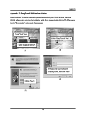
If not, please double click the CD-ROM device icon in "My computer", and execute the setup.exe. Appendix RApepvenisdiixoEn: EHaissyTtounreyIII Utilities Installation Insert the driver CD-title that came with your motherboard into your name and company name, then click "Next". (4) 73 Press "Tools" icon. 1.Click "Gigabyte Utilities". (1) 2.Click "Easy Tune III Ver 3.3 (2) 3.Click "Next". (3) 4. Please enter your CD-ROM driver, the driver CD-title will auto start and show the installation guide.
If not, please double click the CD-ROM device icon in "My computer", and execute the setup.exe. Appendix RApepvenisdiixoEn: EHaissyTtounreyIII Utilities Installation Insert the driver CD-title that came with your motherboard into your name and company name, then click "Next". (4) 73 Press "Tools" icon. 1.Click "Gigabyte Utilities". (1) 2.Click "Easy Tune III Ver 3.3 (2) 3.Click "Next". (3) 4. Please enter your CD-ROM driver, the driver CD-title will auto start and show the installation guide.
User Manual
Page 82
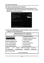
...: Setup F8: Boot Menu F12: Network boot Press any key to highlight the item "BIOS FEATURES SETUP". GA-7VTXE/GA-7VTXH Motherboard STEP 4: Make sure the system will boot from the floppy disk. Please press key to enter BIOS setup main menu when system is 300/100MHz Checking NVRAM 262144KB Wait... All Rights Reserved STANDARD CMOS SETUP INTEGRATED PERIPHERALS BIOS FEATURES SETUP HARDWARE MONITOR & MISC SETUP CHIPSET FEATURES SETUP SUPERVISOR PASSWORD POWER MANAGEMENT SETUP USER PASSWORD PNP / PCI CONFIGURATION IDE HDD AUTO DETECTION LOAD FAIL-SAFE DEFAULTS SAVE & EXIT SETUP LOAD...
...: Setup F8: Boot Menu F12: Network boot Press any key to highlight the item "BIOS FEATURES SETUP". GA-7VTXE/GA-7VTXH Motherboard STEP 4: Make sure the system will boot from the floppy disk. Please press key to enter BIOS setup main menu when system is 300/100MHz Checking NVRAM 262144KB Wait... All Rights Reserved STANDARD CMOS SETUP INTEGRATED PERIPHERALS BIOS FEATURES SETUP HARDWARE MONITOR & MISC SETUP CHIPSET FEATURES SETUP SUPERVISOR PASSWORD POWER MANAGEMENT SETUP USER PASSWORD PNP / PCI CONFIGURATION IDE HDD AUTO DETECTION LOAD FAIL-SAFE DEFAULTS SAVE & EXIT SETUP LOAD...
User Manual
Page 86
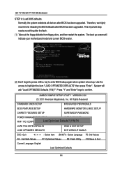
... : 0009 Intel(R) Pentium(R) 4 Processor-1.50 GHz RamBus/Host Frequency is boot up screen will ask "Load OPTIMIZED Defaults (Y/N)?" Press "Y" and "Enter" keys to highlight the item "LOAD OPTIMIZED DEFAULTS" then press "Enter". This important step resets everything after BIOS has been upgraded. AMIBIOS SIMPLE SETUP UTILITY - VERSION 2.00 (C) 2001 American Megatrends, Inc. Normally the system redetects all devices after the flash. (1) Take out the floppy diskette from floppy drive, and then restart...
... : 0009 Intel(R) Pentium(R) 4 Processor-1.50 GHz RamBus/Host Frequency is boot up screen will ask "Load OPTIMIZED Defaults (Y/N)?" Press "Y" and "Enter" keys to highlight the item "LOAD OPTIMIZED DEFAULTS" then press "Enter". This important step resets everything after BIOS has been upgraded. AMIBIOS SIMPLE SETUP UTILITY - VERSION 2.00 (C) 2001 American Megatrends, Inc. Normally the system redetects all devices after the flash. (1) Take out the floppy diskette from floppy drive, and then restart...
User Manual
Page 88
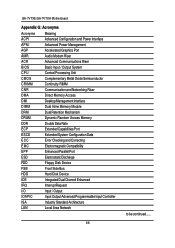
.../GA-7VTXH Motherboard Appendix G: Acronyms Acronyms Meaning ACPI Advanced Configuration and Power Interface APM Advanced Power Management AGP Accelerated Graphics Port AMR Audio Modem Riser ACR Advanced Communications Riser BIOS Basic Input / Output System CPU Central Processing Unit CMOS Complementary Metal Oxide Semiconductor CRIMM Continuity RIMM CNR Communication and Networking Riser DMA Direct Memory Access DMI Desktop Management Interface DIMM Dual Inline Memory Module DRM Dual Retention Mechanism DRAM Dynamic Random Access Memory...
.../GA-7VTXH Motherboard Appendix G: Acronyms Acronyms Meaning ACPI Advanced Configuration and Power Interface APM Advanced Power Management AGP Accelerated Graphics Port AMR Audio Modem Riser ACR Advanced Communications Riser BIOS Basic Input / Output System CPU Central Processing Unit CMOS Complementary Metal Oxide Semiconductor CRIMM Continuity RIMM CNR Communication and Networking Riser DMA Direct Memory Access DMI Desktop Management Interface DIMM Dual Inline Memory Module DRM Dual Retention Mechanism DRAM Dynamic Random Access Memory...


