User Manual
Page 1
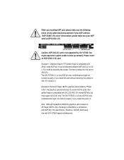
... Note : Although Gigabyte's AG32S(G) graphics card is based on ATi Rage 128 Pro chip, the design of AG32S(G) is not supported by VIA® KT600. Please insert an AGP 4X/8X(1.5V) card Example 1: Diamond Vipper V770 golden finger is 2X(3.3V). The GA-7VT600(-L) (or any AGP 4X only) motherboards might experience system... cards made by adjusting the jumper. You might not function properly, If you install this card is compatible with AGP 4X(1.5V) specification. The GA-7VT600(-L) (or any AGP 4X only) motherboards might not function properly, if you install this card in it .
... Note : Although Gigabyte's AG32S(G) graphics card is based on ATi Rage 128 Pro chip, the design of AG32S(G) is not supported by VIA® KT600. Please insert an AGP 4X/8X(1.5V) card Example 1: Diamond Vipper V770 golden finger is 2X(3.3V). The GA-7VT600(-L) (or any AGP 4X only) motherboards might experience system... cards made by adjusting the jumper. You might not function properly, If you install this card is compatible with AGP 4X(1.5V) specification. The GA-7VT600(-L) (or any AGP 4X only) motherboards might not function properly, if you install this card in it .

User Manual
Page 2
M The author assumes no responsibility for any labels on motherboard, thismay void the warranty of this document nor does the author make a commitment to rapid change in this motherboard. M Third-party brands and names are the property of this booklet. M Please do not remove any errors or omissions that may appear in technology, some of the specifications might be out of date before publication of their respective owners. M Due to update the information contained herein.
M The author assumes no responsibility for any labels on motherboard, thismay void the warranty of this document nor does the author make a commitment to rapid change in this motherboard. M Third-party brands and names are the property of this booklet. M Please do not remove any errors or omissions that may appear in technology, some of the specifications might be out of date before publication of their respective owners. M Due to update the information contained herein.

User Manual
Page 4
... complies with part 15 of Industry, CA 91748 Phone/Fax No: (818) 854-9338/ (818) 854-9339 hereby declares that the product Product Name: Motherboard Model Number:GA-7VT600 Conforms to the following two conditions: (1) This device may not cause harmful and (2) this device must accept any inference received, including that may cause...
... complies with part 15 of Industry, CA 91748 Phone/Fax No: (818) 854-9338/ (818) 854-9339 hereby declares that the product Product Name: Motherboard Model Number:GA-7VT600 Conforms to the following two conditions: (1) This device may not cause harmful and (2) this device must accept any inference received, including that may cause...
User Manual
Page 5
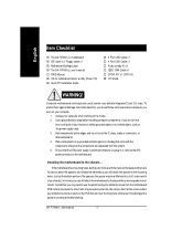
GA-7VT600(-L) AMD Socket A Processor Motherboard USER'S MANUAL AMD Athlon™/ Athlon™ XP / Duron™ Socket A Processor Motherboard Rev. 1001 12ME-7VT600-1001
GA-7VT600(-L) AMD Socket A Processor Motherboard USER'S MANUAL AMD Athlon™/ Athlon™ XP / Duron™ Socket A Processor Motherboard Rev. 1001 12ME-7VT600-1001

User Manual
Page 6
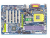
English Table of Content Item Checklist 4 WARNING 4 Chapter 1 Introduction 5 Features Summary 5 GA-7VT600(-L) Motherboard Layout 7 Block Diagram 8 Chapter 2 Hardware Installation Process 9 Step 1: Install the Central Processing Unit (CPU 10 Step1-1: CPU Speed Setup 10 Step1-2: CPU Installation 11 Step1-3:... 18 Chapter 3 BIOS Setup 31 The Main Menu (For example: BIOS Ver. :E1 32 Standard CMOS Features 34 Advanced BIOS Features 37 Integrated Peripherals 39 GA-7VT600(-L) Motherboard - 2 -
English Table of Content Item Checklist 4 WARNING 4 Chapter 1 Introduction 5 Features Summary 5 GA-7VT600(-L) Motherboard Layout 7 Block Diagram 8 Chapter 2 Hardware Installation Process 9 Step 1: Install the Central Processing Unit (CPU 10 Step1-1: CPU Speed Setup 10 Step1-2: CPU Installation 11 Step1-3:... 18 Chapter 3 BIOS Setup 31 The Main Menu (For example: BIOS Ver. :E1 32 Standard CMOS Features 34 Advanced BIOS Features 37 Integrated Peripherals 39 GA-7VT600(-L) Motherboard - 2 -
User Manual
Page 8
... is switched off , so be a little hard to the chassis... Sometimes you can still attach the motherboard to the mounting holes. GA-7VT600(-L) Motherboard - 4 - Place components on a grounded antistatic pad or on the bag that are near by the...the screw contact any printed circuit write or parts on the motherboard. English Item Checklist þ The GA-7VT600(-L) motherboard þ IDE cable x 2/ Floppy cable x 1 þ Motherboard Settings Label þ The GA-7VT600(-L) user's manual o RAID Manual þ CD for motherboard driver & utility (Driver CD) þ Quick PC ...
... is switched off , so be a little hard to the chassis... Sometimes you can still attach the motherboard to the mounting holes. GA-7VT600(-L) Motherboard - 4 - Place components on a grounded antistatic pad or on the bag that are near by the...the screw contact any printed circuit write or parts on the motherboard. English Item Checklist þ The GA-7VT600(-L) motherboard þ IDE cable x 2/ Floppy cable x 1 þ Motherboard Settings Label þ The GA-7VT600(-L) user's manual o RAID Manual þ CD for motherboard driver & utility (Driver CD) þ Quick PC ...
User Manual
Page 10
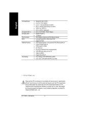
... — Supports @BIOS — Supports EasyTune 4 — Over Voltage (CPU/AGP/DDR) by BIOS — Over Clock (CPU/AGP/DDR/PCI) by BIOS " * " FOR GA-7VT600-L Only. GA-7VT600(-L) Motherboard - 6 - We don't recommend you to set the CPU host frequency in VIA VT8235 / VT8237 Chipset — RealTek RTL8101L — 1 RJ45 port — PS/2 Keyboard interface...
... — Supports @BIOS — Supports EasyTune 4 — Over Voltage (CPU/AGP/DDR) by BIOS — Over Clock (CPU/AGP/DDR/PCI) by BIOS " * " FOR GA-7VT600-L Only. GA-7VT600(-L) Motherboard - 6 - We don't recommend you to set the CPU host frequency in VIA VT8235 / VT8237 Chipset — RealTek RTL8101L — 1 RJ45 port — PS/2 Keyboard interface...

User Manual
Page 12
... Ports IDE Channels 33 MHz PS/2 KB/Mouse COM Ports MIC LINE-IN LINE-OUT PCICLK (33MHz) USBCLK (48MHz) 14.318 MHz 33 MHz " * " FOR GA-7VT600-L Only. GA-7VT600(-L) Motherboard CLK HCLK+/- (100/133/166/200MHz) CPUCLK+/- (100/133/166/200MHz) GEN AGPCLK (66MHz) V_Link (66MHz) - 8 -
... Ports IDE Channels 33 MHz PS/2 KB/Mouse COM Ports MIC LINE-IN LINE-OUT PCICLK (33MHz) USBCLK (48MHz) 14.318 MHz 33 MHz " * " FOR GA-7VT600-L Only. GA-7VT600(-L) Motherboard CLK HCLK+/- (100/133/166/200MHz) CPUCLK+/- (100/133/166/200MHz) GEN AGPCLK (66MHz) V_Link (66MHz) - 8 -
User Manual
Page 14
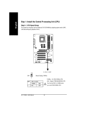
English Step 1: Install the Central Processing Unit (CPU) Step1-1: CPU Speed Setup The system bus frequency can be switched at 100/133/166MHz by adjusting system switch (SW1). (The internal frequency depend on CPU.) O: ON / X :OFF ON SW1 Default Setting: 100MHz 1 SW1 CPU CLOCK 100MHz Auto 1 ON OFF 100MHz : Fix FSB 200MHz CPU Auto : Support FSB 266/333 MHz CPU You must set SW1 to 100MHz when you used FSB 200MHz CPU. GA-7VT600(-L) Motherboard - 10 -
English Step 1: Install the Central Processing Unit (CPU) Step1-1: CPU Speed Setup The system bus frequency can be switched at 100/133/166MHz by adjusting system switch (SW1). (The internal frequency depend on CPU.) O: ON / X :OFF ON SW1 Default Setting: 100MHz 1 SW1 CPU CLOCK 100MHz Auto 1 ON OFF 100MHz : Fix FSB 200MHz CPU Auto : Support FSB 266/333 MHz CPU You must set SW1 to 100MHz when you used FSB 200MHz CPU. GA-7VT600(-L) Motherboard - 10 -

User Manual
Page 15
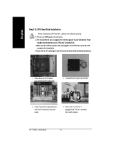
... the insert orientation. Pull up the CPU socket lever and up to the following warning: 1.Please make sure the CPU type is supported by the motherboard. 2.If you do not match the CPU socket Pin 1 and CPU cut edge on the CPU upper corner. Hardware Installation Process English Step1-2: CPU Installation...
... the insert orientation. Pull up the CPU socket lever and up to the following warning: 1.Please make sure the CPU type is supported by the motherboard. 2.If you do not match the CPU socket Pin 1 and CPU cut edge on the CPU upper corner. Hardware Installation Process English Step1-2: CPU Installation...
User Manual
Page 16
Please refer to the following warning: 1. GA-7VT600(-L) Motherboard - 12 - Please use AMD approved cooling fan. 2. Make sure the CPU fan power cable is plugged to the CPU fan connector, than install complete. Use ...
Please refer to the following warning: 1. GA-7VT600(-L) Motherboard - 12 - Please use AMD approved cooling fan. 2. Make sure the CPU fan power cable is plugged to the CPU fan connector, than install complete. Use ...

User Manual
Page 17
... Slot. Please change the insert orientation. The BIOS will cause improper installation. Wrong orientation will automatically detects memory type and size. Hardware Installation Process The motherboard has 3 dual inline memory module(DIMM) sockets. The DIMM module can only fit in one direction due to the one direction due to the following...
... Slot. Please change the insert orientation. The BIOS will cause improper installation. Wrong orientation will automatically detects memory type and size. Hardware Installation Process The motherboard has 3 dual inline memory module(DIMM) sockets. The DIMM module can only fit in one direction due to the one direction due to the following...

User Manual
Page 18
... infrastructure, DDR (Double Data Rate) memory is a sensible evolutionary solution for the PC industry that are suitable for small form factor desktops and notebook applications. GA-7VT600(-L) Motherboard - 14 - DDR memory is a high performance and cost-effective solution that allows easy adoption for memory vendors, OEMs and system integrators. DDR SDRAM will offer...
... infrastructure, DDR (Double Data Rate) memory is a sensible evolutionary solution for the PC industry that are suitable for small form factor desktops and notebook applications. GA-7VT600(-L) Motherboard - 14 - DDR memory is a high performance and cost-effective solution that allows easy adoption for memory vendors, OEMs and system integrators. DDR SDRAM will offer...

User Manual
Page 19
... the related expansion card's instruction document before install the expansion card into expansion slot in the slot. 5. Power on the card are indeed seated in motherboard. 4. Press the expansion card firmly into the computer. 2. Remove your computer's chassis cover. 7. AGP Card Please carefully pull out the small whitedrawable bar at the...
... the related expansion card's instruction document before install the expansion card into expansion slot in the slot. 5. Power on the card are indeed seated in motherboard. 4. Press the expansion card firmly into the computer. 2. Remove your computer's chassis cover. 7. AGP Card Please carefully pull out the small whitedrawable bar at the...

User Manual
Page 20
... / COMB) Parallel Port (25 pin Female) This connector supports 2 standard COM ports and 1 Parallel port. mouse and modem etc. COMA COMB Serial Port (9 pin Male) GA-7VT600(-L) Motherboard - 16 - Device like printer can be connected to Serial ports. can be connected to Parallel port; English Step 4: Connect ribbon cables, cabinet wires and power...
... / COMB) Parallel Port (25 pin Female) This connector supports 2 standard COM ports and 1 Parallel port. mouse and modem etc. COMA COMB Serial Port (9 pin Male) GA-7VT600(-L) Motherboard - 16 - Device like printer can be connected to Serial ports. can be connected to Parallel port; English Step 4: Connect ribbon cables, cabinet wires and power...

User Manual
Page 22
GA-7VT600(-L) Motherboard - 18 - English Step4-2 : Connectors Introduction 1 6 3 5 10 12 8 13 14 2 11 4 15 1) CPU_FAN 2) SYS_FAN 3) ATX_POWER 4) IDE1/IDE2 5) FDD 6) RAM_LED 7) PWR_LED 8) BATTERY 9) F_PANEL 16 17 18 79 10) F_AUDIO 11) SUR_CEN 12) CD_IN 13) AUX_IN 14) SPDIF_IO 15) F_USB1/F_USB2 16) GAME 17) MODEM * 18) CI " * " FOR GA-7VT600-L Only.
GA-7VT600(-L) Motherboard - 18 - English Step4-2 : Connectors Introduction 1 6 3 5 10 12 8 13 14 2 11 4 15 1) CPU_FAN 2) SYS_FAN 3) ATX_POWER 4) IDE1/IDE2 5) FDD 6) RAM_LED 7) PWR_LED 8) BATTERY 9) F_PANEL 16 17 18 79 10) F_AUDIO 11) SUR_CEN 12) CD_IN 13) AUX_IN 14) SPDIF_IO 15) F_USB1/F_USB2 16) GAME 17) MODEM * 18) CI " * " FOR GA-7VT600-L Only.

User Manual
Page 24
... connect CDROM to the mainboard. English 3) ATX_POWER (ATX Power) AC power cord should only be the same side with the Pin1. 40 2 39 1 IDE2 IDE1 GA-7VT600(-L) Motherboard - 20 - Pin No. The red stripe of the ribbon cable must be connected to your power supply unit after ATX power cable and other related...
... connect CDROM to the mainboard. English 3) ATX_POWER (ATX Power) AC power cord should only be the same side with the Pin1. 40 2 39 1 IDE2 IDE1 GA-7VT600(-L) Motherboard - 20 - Pin No. The red stripe of the ribbon cable must be connected to your power supply unit after ATX power cable and other related...

User Manual
Page 26
... battery, wait for 30 second. 3.Re-install the battery. 4.Plug the power cord and turn to the manufacturer's instructions. Definition 1 MPD+ 1 2 MPD3 MPD- 8) BATTERY (Battery) GA-7VT600(-L) Motherboard + CAUTION v Danger of used batteries according to another color. v Replace only with the system power indicator to indicate whether the system is incorrectly replaced. v Dispose...
... battery, wait for 30 second. 3.Re-install the battery. 4.Plug the power cord and turn to the manufacturer's instructions. Definition 1 MPD+ 1 2 MPD3 MPD- 8) BATTERY (Battery) GA-7VT600(-L) Motherboard + CAUTION v Danger of used batteries according to another color. v Replace only with the system power indicator to indicate whether the system is incorrectly replaced. v Dispose...

User Manual
Page 28
..., you are buying support front audio connector, please contact your dealer. 10 9 21 Pin No. Definition 1 SUR OUTL 2 SUR OUTR 3 GND 4 No Pin 5 CENTER_OUT 6 BASS_OUT GA-7VT600(-L) Motherboard - 24 - Definition 1 MIC 2 GND 3 REF 4 POWER 5 FrontAudio(R) 6 RearAudio(R) 7 Reserved 8 No Pin 9 FrontAudio (L) 10 RearAudio(L) 11) SUR_CEN Please contact your nearest dealer for optional SUR_CEN cable...
..., you are buying support front audio connector, please contact your dealer. 10 9 21 Pin No. Definition 1 SUR OUTL 2 SUR OUTR 3 GND 4 No Pin 5 CENTER_OUT 6 BASS_OUT GA-7VT600(-L) Motherboard - 24 - Definition 1 MIC 2 GND 3 REF 4 POWER 5 FrontAudio(R) 6 RearAudio(R) 7 Reserved 8 No Pin 9 FrontAudio (L) 10 RearAudio(L) 11) SUR_CEN Please contact your nearest dealer for optional SUR_CEN cable...

User Manual
Page 30
... when your local dealer. 2 10 19 Pin No. 1 2 3 4 5 6 7 8 9 10 Definition Power Power USB DXUSB DyUSB DX+ USB Dy+ GND GND No Pin USB Over Current GA-7VT600(-L) Motherboard - 26 - Definition 1 VCC 2 No Pin 3 SPDIF 4 SPDIFI 5 GND 6 GND 15) F_ USB1 / F_USB2(Front USB Connector, Yellow ) Be careful with the polarity of the SPDIF_IO...
... when your local dealer. 2 10 19 Pin No. 1 2 3 4 5 6 7 8 9 10 Definition Power Power USB DXUSB DyUSB DX+ USB Dy+ GND GND No Pin USB Over Current GA-7VT600(-L) Motherboard - 26 - Definition 1 VCC 2 No Pin 3 SPDIF 4 SPDIFI 5 GND 6 GND 15) F_ USB1 / F_USB2(Front USB Connector, Yellow ) Be careful with the polarity of the SPDIF_IO...


