
Manual
Page 1
GA-7TESM Dual Xeon Processor Motherboard USER'S Manual Xeon® Processor Motherboard Rev. 1001 * The WEEE marking on the product indicates this product must not be disposed of with user's other household waste and must be handed over to a designated collection point for the recycling of waste electrical and electronic equipment!! * The WEEE marking applies only in European Union's member states.
GA-7TESM Dual Xeon Processor Motherboard USER'S Manual Xeon® Processor Motherboard Rev. 1001 * The WEEE marking on the product indicates this product must not be disposed of with user's other household waste and must be handed over to a designated collection point for the recycling of waste electrical and electronic equipment!! * The WEEE marking applies only in European Union's member states.

Manual
Page 2
... Configuration ...42 Advanced Chipset Configuration 44 PCI Configuration ...48 SATA Configuration ...50 I /O Back Panel Introduction 17 2.4. Considerations Prior to Installation 5 1.2. Installing Heat Sink 12 2.2. GA-7TEWH-RH Motherboard Component 8 Chapter 2 Hardware Installation Process 11 2.1. Connect ribbon cables, cabinet wires, and power supply 17 2.3.1. Features Summary 6 1.3. I /O DeviceConfiguration 52 Boot DeviceConfiguration 54 Haradware Monitor...
... Configuration ...42 Advanced Chipset Configuration 44 PCI Configuration ...48 SATA Configuration ...50 I /O Back Panel Introduction 17 2.4. Considerations Prior to Installation 5 1.2. Installing Heat Sink 12 2.2. GA-7TEWH-RH Motherboard Component 8 Chapter 2 Hardware Installation Process 11 2.1. Connect ribbon cables, cabinet wires, and power supply 17 2.3.1. Features Summary 6 1.3. I /O DeviceConfiguration 52 Boot DeviceConfiguration 54 Haradware Monitor...
Manual
Page 3
English GA-7TESM Motherboard System Management ...62 Console Redirection ...63 Boot ...65 Exit ...66 3
English GA-7TESM Motherboard System Management ...62 Console Redirection ...63 Boot ...65 Exit ...66 3

Manual
Page 4
Item Checklist The GA-7TESM motherboard Serial ATA cable x 6 I/O Shield Kit CD for motherboard driver & utility GA-7TESM quick reference guide Introduction * The items listed above are for reference only, and are subject to change without notice. 4
Item Checklist The GA-7TESM motherboard Serial ATA cable x 6 I/O Shield Kit CD for motherboard driver & utility GA-7TESM quick reference guide Introduction * The items listed above are for reference only, and are subject to change without notice. 4
Manual
Page 5
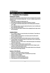
... user manual. 3. Damage due to be an unofficial Gigabyte product. 5 Damage due to come in contact with the motherboard circuit or its power cord. 2. To prevent damage to the motherboard, please do not allow screws to use exceeding the permitted parameters. 6. If you are connected. 4. English GA-7TESM Motherboard Chapter 1 Introduction 1.1. Damage as a result of an...
... user manual. 3. Damage due to be an unofficial Gigabyte product. 5 Damage due to come in contact with the motherboard circuit or its power cord. 2. To prevent damage to the motherboard, please do not allow screws to use exceeding the permitted parameters. 6. If you are connected. 4. English GA-7TESM Motherboard Chapter 1 Introduction 1.1. Damage as a result of an...
Manual
Page 7
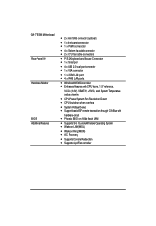
English GA-7TESM Motherboard Rear Panel I/O Hardware Monitor BIOS Additional Features 2 x mini SAS connector (optional) 1 x front panel connecctor 1 x PSMI connecctor 4 x System fan cable connector 2 x ...
English GA-7TESM Motherboard Rear Panel I/O Hardware Monitor BIOS Additional Features 2 x mini SAS connector (optional) 1 x front panel connecctor 1 x PSMI connecctor 4 x System fan cable connector 2 x ...

Manual
Page 8
GA-7TESM Motherboard Component Code Description CPU0 Primary CPU CPU1 Secondary CPU U24 Intel Tylersburg-36D IOH U39 Intel ICH10R U148 ITE IT8720F Super I/O controller U29 LSI SAS2008 ...
GA-7TESM Motherboard Component Code Description CPU0 Primary CPU CPU1 Secondary CPU U24 Intel Tylersburg-36D IOH U39 Intel ICH10R U148 ITE IT8720F Super I/O controller U29 LSI SAS2008 ...

Manual
Page 10
English GA-7TESM Motherboard 10 7 34 35 5036 54 37 9 9 8 38 33 51 53 52 55 32 56 31 4 30 29 5 28 39 27 6 26 17 16 15 14 13 12 44 11 21 22 23 2 41 3 25 24 48 45 1 46 20 19 18 47 49 43 40 42 10
English GA-7TESM Motherboard 10 7 34 35 5036 54 37 9 9 8 38 33 51 53 52 55 32 56 31 4 30 29 5 28 39 27 6 26 17 16 15 14 13 12 44 11 21 22 23 2 41 3 25 24 48 45 1 46 20 19 18 47 49 43 40 42 10
Manual
Page 11
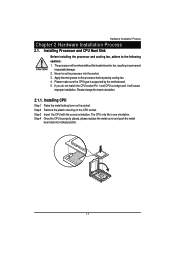
... grease on the socket. Please change the insert orientation. 2.1.1. Step 3 Insert the CPU with the correct orientation. Step 4 Once the CPU is supported by the motherboard. 5. The CPU only fits in permanent irreparable damage. 2. The processor will cause improper installation. Please make sure the CPU type is properly placed, please replace...
... grease on the socket. Please change the insert orientation. 2.1.1. Step 3 Insert the CPU with the correct orientation. Step 4 Once the CPU is supported by the motherboard. 5. The CPU only fits in permanent irreparable damage. 2. The processor will cause improper installation. Please make sure the CPU type is properly placed, please replace...

Manual
Page 12
Installing Heat Sink Step 1 Attach the heat sink clip to the processor fanconnector 2 2 2 1 12 Step 3 Connect processor fan can cable to the processor socket. English GA-7TESM Motherboard 2.1.2. Step 2 Secure the cooing fan with screws.
Installing Heat Sink Step 1 Attach the heat sink clip to the processor fanconnector 2 2 2 1 12 Step 3 Connect processor fan can cable to the processor socket. English GA-7TESM Motherboard 2.1.2. Step 2 Secure the cooing fan with screws.

Manual
Page 13
A memory module can be inserted only in only one direction. The motherboard supports DDR3 memory modules, whereby BIOS will automatically detect memory capacity and specifications. The memory capacity used can be installed in...is switched off to prevent hardware damage. 3. Before installing or removing memory modules, please make sure that the computer power is supported by the motherboard. Hardware Installation Process 2.2. Installing memory modules Before installing the memory modules, please comply with similar capacity, specifications and brand. 2. Memory modules ...
A memory module can be inserted only in only one direction. The motherboard supports DDR3 memory modules, whereby BIOS will automatically detect memory capacity and specifications. The memory capacity used can be installed in...is switched off to prevent hardware damage. 3. Before installing or removing memory modules, please make sure that the computer power is supported by the motherboard. Hardware Installation Process 2.2. Installing memory modules Before installing the memory modules, please comply with similar capacity, specifications and brand. 2. Memory modules ...

Manual
Page 15
English GA-7TESM Motherboard U-DIMM Population Table Channel A Channel B Channel C P0C0D0 P1C0D0 P0C0D1 P1C0D1 P0C0D2 P1C0D2 P0C1D0 P1C1D0 P0C1D1 P1C1D1 P0C1D2 P1C1D2 P0C2D0 P1C2D0 P0C2D1 P1C2D1 P0C2D2 P1C2D2 Single-...
English GA-7TESM Motherboard U-DIMM Population Table Channel A Channel B Channel C P0C0D0 P1C0D0 P0C0D1 P1C0D1 P0C0D2 P1C0D2 P0C1D0 P1C1D0 P0C1D1 P1C1D1 P0C1D2 P1C1D2 P0C2D0 P1C2D0 P0C2D1 P1C2D1 P0C2D2 P1C2D2 Single-...

Manual
Page 16
English GA-7TESM Motherboard R-DIMM Population Table Channel A Channel B Channel C P0C0D0 P1C0D0 P0C0D1 P1C0D1 P0C0D2 P1C0D2 P0C1D0 P1C1D0 P0C1D1 P1C1D1 P0C1D2 P1C1D2 P0C2D0 P1C2D0 P0C2D1 P1C2D1 P0C2D2 P1C2D2 Single-...
English GA-7TESM Motherboard R-DIMM Population Table Channel A Channel B Channel C P0C0D0 P1C0D0 P0C0D1 P1C0D1 P0C0D2 P1C0D2 P0C1D0 P1C1D0 P0C1D1 P1C1D1 P0C1D2 P1C1D2 P0C2D0 P1C2D0 P0C2D1 P1C2D1 P0C2D2 P1C2D2 Single-...
Manual
Page 18
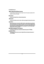
... or data processing devices. KVM Server Management 10/100 LAN Port The LAN port provides Internet connection with data transfer speeds of 10/100Mbps. English GA-7TESM Motherboard PS/2 Keyboard and PS/2 Mouse Connector To install a PS/2 port keyboard and mouse, plug the mouse to the upper port (green) and the keyboard to...
... or data processing devices. KVM Server Management 10/100 LAN Port The LAN port provides Internet connection with data transfer speeds of 10/100Mbps. English GA-7TESM Motherboard PS/2 Keyboard and PS/2 Mouse Connector To install a PS/2 port keyboard and mouse, plug the mouse to the upper port (green) and the keyboard to...

Manual
Page 20
Connectors Introduction 14 17 4 5 16 6 18 7 9 10 15 3 1 8 2 11 12 13 1. COMB1 5. SATA0-5 (SATA data cable connector) 8. FAN_CPU1 (CPU1 fan cable connector) 15. SGPIO_JP2 18. ATX1 2. 12V_AUX1 3. 12V_AUX0 4. English GA-7TESM Motherboard 2.4. SYS_FAN3 (System fan connector) 13. BAT1 16. FAN_CPU0 (CPU0 fan cable connector) 14. SYS_FAN4 (System fan connector) 10. SYS_FAN2 (System fan connector) 12. SGPIO_JP1 20 F_PANEL1 7. SYS_FAN1 (System fan connector) 11. PSMI1 9. IPMB1 17. USB1 (Front USB cable connector) 6.
Connectors Introduction 14 17 4 5 16 6 18 7 9 10 15 3 1 8 2 11 12 13 1. COMB1 5. SATA0-5 (SATA data cable connector) 8. FAN_CPU1 (CPU1 fan cable connector) 15. SGPIO_JP2 18. ATX1 2. 12V_AUX1 3. 12V_AUX0 4. English GA-7TESM Motherboard 2.4. SYS_FAN3 (System fan connector) 13. BAT1 16. FAN_CPU0 (CPU0 fan cable connector) 14. SYS_FAN4 (System fan connector) 10. SYS_FAN2 (System fan connector) 12. SGPIO_JP1 20 F_PANEL1 7. SYS_FAN1 (System fan connector) 11. PSMI1 9. IPMB1 17. USB1 (Front USB cable connector) 6.
Manual
Page 21
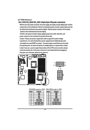
... use a power supply that is able to support the system voltage requirements. Align the power connector with its proper location on the motherboard before plugging in the power cord; English GA-7TESM Motherboard 1/2/3 ) ATX1/12V_AUX0/12V_AUX1 (24-pin/8-pin ATX power connectors) With the use of the power connector, the power supply can lead...
... use a power supply that is able to support the system voltage requirements. Align the power connector with its proper location on the motherboard before plugging in the power cord; English GA-7TESM Motherboard 1/2/3 ) ATX1/12V_AUX0/12V_AUX1 (24-pin/8-pin ATX power connectors) With the use of the power connector, the power supply can lead...

Manual
Page 23
Check the pin assignment carefully while you connect the front USB cable, incorrect connection between the cable and connector will make the device unable to work or even damage it. For optional front USB cable, please contact your local dealer. 12 9 10 Pin No. 1 2 3 4 5 6 7 8 9 10 Definition 5V power 5V power -FUSB2 -FUSB3 +FUSB2 +FUSB3 GND GND NC NC 23 English GA-7TESM Motherboard 4 ) COMB1 12 9 10 Pin No. 1 2 3 4 5 6 7 8 9 10 Definition DCDSIN2 SOUT2 DTR2GND DSR2RTS2CTS2RI2NC 5 ) USB1 (USB cable connector) Be careful with the polarity of the front USB connector.
Check the pin assignment carefully while you connect the front USB cable, incorrect connection between the cable and connector will make the device unable to work or even damage it. For optional front USB cable, please contact your local dealer. 12 9 10 Pin No. 1 2 3 4 5 6 7 8 9 10 Definition 5V power 5V power -FUSB2 -FUSB3 +FUSB2 +FUSB3 GND GND NC NC 23 English GA-7TESM Motherboard 4 ) COMB1 12 9 10 Pin No. 1 2 3 4 5 6 7 8 9 10 Definition DCDSIN2 SOUT2 DTR2GND DSR2RTS2CTS2RI2NC 5 ) USB1 (USB cable connector) Be careful with the polarity of the front USB connector.
Manual
Page 26
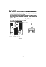
.... 1 FAN_CPU1 FAN_SYS4 FAN_SYS1 FAN_SYS2 FAN_SYS3 FAN_CPU0 1 Pin No. 1 2 3 4 Definition GND 12V Sense Control 26 Most coolers are designed with color-coded power connector wires. English GA-7TESM Motherboard 9~14 ) FAN_CPU0/1 / FAN_SYS1/2/3/4 (CPU fan / System fan cable connectors) The cooler fan power connector supplies a +12V power voltage via a 3-pin/4-pin(CPU_FAN) power connector and...
.... 1 FAN_CPU1 FAN_SYS4 FAN_SYS1 FAN_SYS2 FAN_SYS3 FAN_CPU0 1 Pin No. 1 2 3 4 Definition GND 12V Sense Control 26 Most coolers are designed with color-coded power connector wires. English GA-7TESM Motherboard 9~14 ) FAN_CPU0/1 / FAN_SYS1/2/3/4 (CPU fan / System fan cable connectors) The cooler fan power connector supplies a +12V power voltage via a 3-pin/4-pin(CPU_FAN) power connector and...

Manual
Page 28
SGPIO_JP2 SGPIO_JP1 SGPIO_JP1 1 Pin No. English GA-7TESM Motherboard 17/18 ) SGPIO_JP2/SGPIO_JP1 (ICH10 SGPIO connectors) SGPIO is stands for Serial General Purpose Input/Output which is a storage controller located inside a server, desktop, rack ...
SGPIO_JP2 SGPIO_JP1 SGPIO_JP1 1 Pin No. English GA-7TESM Motherboard 17/18 ) SGPIO_JP2/SGPIO_JP1 (ICH10 SGPIO connectors) SGPIO is stands for Serial General Purpose Input/Output which is a storage controller located inside a server, desktop, rack ...

Manual
Page 30
English GA-7TESM Motherboard 1 ) CLR_CMOS1 (Clear CMOS jumper) You may clear the CMOS data to its default values by this jumper. 1 1-2 close: Normal operation (Default setting) 1 2-3 close: Clear CMOS 2 ) ...
English GA-7TESM Motherboard 1 ) CLR_CMOS1 (Clear CMOS jumper) You may clear the CMOS data to its default values by this jumper. 1 1-2 close: Normal operation (Default setting) 1 2-3 close: Clear CMOS 2 ) ...


