
Manual
Page 2
... 2 Hardware Installation Process 11 2.1. Connectors Introduction 20 2.5. Jumper Setting 29 Chapter 3 BIOS Setup 31 Main ...33 Advanced 34 Processor Configuration 35 Power Management ...39 Memory Configuration ...42 Advanced Chipset Configuration 44 PCI Configuration ...48 SATA Configuration ...50 I /O Back Panel Introduction 17 2.4. Installing CPU ...11 2.1.2. Installing memory modules 13 2.3. I /O DeviceConfiguration 52 Boot DeviceConfiguration 54 Haradware Monitor ...56 Power ...57 Security ...59 Server ...61 2 Connect ribbon cables, cabinet wires, and power supply 17...
... 2 Hardware Installation Process 11 2.1. Connectors Introduction 20 2.5. Jumper Setting 29 Chapter 3 BIOS Setup 31 Main ...33 Advanced 34 Processor Configuration 35 Power Management ...39 Memory Configuration ...42 Advanced Chipset Configuration 44 PCI Configuration ...48 SATA Configuration ...50 I /O Back Panel Introduction 17 2.4. Installing CPU ...11 2.1.2. Installing memory modules 13 2.3. I /O DeviceConfiguration 52 Boot DeviceConfiguration 54 Haradware Monitor ...56 Power ...57 Security ...59 Server ...61 2 Connect ribbon cables, cabinet wires, and power supply 17...
Manual
Page 5
... or connectors. 3. English GA-7TESM Motherboard Chapter 1 Introduction 1.1. Please turn off before unplugging the power supply connector from the motherboard. Damage due to installation, please follow the instructions below: 1. Prior to wear an electrostatic discharge (ESD) cuff when handling electronic components (CPU, RAM). 4. Before using the product, please verify that the power supply is best to the installation of Non-Warranty 1. Installation Notices 1. To prevent damage to the user...
... or connectors. 3. English GA-7TESM Motherboard Chapter 1 Introduction 1.1. Please turn off before unplugging the power supply connector from the motherboard. Damage due to installation, please follow the instructions below: 1. Prior to wear an electrostatic discharge (ESD) cuff when handling electronic components (CPU, RAM). 4. Before using the product, please verify that the power supply is best to the installation of Non-Warranty 1. Installation Notices 1. To prevent damage to the user...
Manual
Page 6
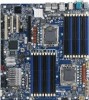
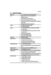
... Introduction Form Factor CPU Chipset Memory I/O Control Expansion Slots SATA RAID Controller On-Board VGA SAS Controller (optional) On-Board LAN Internal Connector 12" x 13" EATX size form factor, 8 layers PCB Supports Dual Intel® Xeon® Nehalem-EP 2S / Westmere processors Xeon® Quad Core in LGA 1366 socket Supports QuickPath Interconnect up to 6.4GT/s Enhanced Intel SpeedStep Technology (EIST) & Demand Based Switch (DBS) Support Intel Virtualization Technology (VT) Intel...
... Introduction Form Factor CPU Chipset Memory I/O Control Expansion Slots SATA RAID Controller On-Board VGA SAS Controller (optional) On-Board LAN Internal Connector 12" x 13" EATX size form factor, 8 layers PCB Supports Dual Intel® Xeon® Nehalem-EP 2S / Westmere processors Xeon® Quad Core in LGA 1366 socket Supports QuickPath Interconnect up to 6.4GT/s Enhanced Intel SpeedStep Technology (EIST) & Demand Based Switch (DBS) Support Intel Virtualization Technology (VT) Intel...
Manual
Page 7
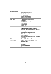
English GA-7TESM Motherboard Rear Panel I/O Hardware Monitor BIOS Additional Features 2 x mini SAS connector (optional) 1 x front panel connecctor 1 x PSMI connecctor 4 x System fan cable connector 2 x CPU fan cable connectors P/S 2 Keyboard and Mouse Connectors 1 x Serial port 4 x USB 2.0 dual-port connector 1 x VGA connector 1 x iKVM LAN port 4 x RJ45 LAN ports Windbond 83792G controller Enhanced features with CPU Vcore, 1.5V reference, VCC3 (3.3V) , VBAT3V, +5VSB, and ...
English GA-7TESM Motherboard Rear Panel I/O Hardware Monitor BIOS Additional Features 2 x mini SAS connector (optional) 1 x front panel connecctor 1 x PSMI connecctor 4 x System fan cable connector 2 x CPU fan cable connectors P/S 2 Keyboard and Mouse Connectors 1 x Serial port 4 x USB 2.0 dual-port connector 1 x VGA connector 1 x iKVM LAN port 4 x RJ45 LAN ports Windbond 83792G controller Enhanced features with CPU Vcore, 1.5V reference, VCC3 (3.3V) , VBAT3V, +5VSB, and ...
Manual
Page 11
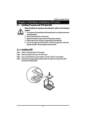
... CPU type is properly placed, please replace the metal cover and push the metal lever back into the socket. 3. Step 2 Remove the plastic covering on the processor before placing cooling fan. 4. Never force the processor into locked position. 11 Hardware Installation Process Chapter 2 Hardware Installation Process 2.1. Installing CPU Step 1 Raise the metal locking lever on the socket. Step 4 Once the CPU is supported by the motherboard. 5. Installing Processor...
... CPU type is properly placed, please replace the metal cover and push the metal lever back into the socket. 3. Step 2 Remove the plastic covering on the processor before placing cooling fan. 4. Never force the processor into locked position. 11 Hardware Installation Process Chapter 2 Hardware Installation Process 2.1. Installing CPU Step 1 Raise the metal locking lever on the socket. Step 4 Once the CPU is supported by the motherboard. 5. Installing Processor...
Manual
Page 18
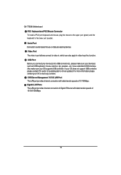
... data processing devices. Gigabit LAN Ports The LAN port provides Internet connection of Gigabit Ethernet with data transfer speeds of 10/100/1000Mbps. 18 English GA-7TESM Motherboard PS/2 Keyboard and PS/2 Mouse Connector To install a PS/2 port keyboard and mouse, plug the mouse to the upper port (green) and the keyboard to the lower port (purple). USB Port Before you connect your device(s) into USB connector(s), please make sure your OS does not support USB controller, please...
... data processing devices. Gigabit LAN Ports The LAN port provides Internet connection of Gigabit Ethernet with data transfer speeds of 10/100/1000Mbps. 18 English GA-7TESM Motherboard PS/2 Keyboard and PS/2 Mouse Connector To install a PS/2 port keyboard and mouse, plug the mouse to the upper port (green) and the keyboard to the lower port (purple). USB Port Before you connect your device(s) into USB connector(s), please make sure your OS does not support USB controller, please...

Manual
Page 20
SYS_FAN3 (System fan connector) 13. FAN_CPU1 (CPU1 fan cable connector) 15. SGPIO_JP1 20 SYS_FAN4 (System fan connector) 10. BAT1 16. IPMB1 17. Connectors Introduction 14 17 4 5 16 6 18 7 9 10 15 3 1 8 2 11 12 13 1. SATA0-5 (SATA data cable connector) 8. SYS_FAN2 (System fan connector) 12. English GA-7TESM Motherboard 2.4. PSMI1 9. USB1 (Front USB cable connector) 6. SYS_FAN1 (System fan connector) 11. F_PANEL1 7. FAN_CPU0 (CPU0 fan cable connector) 14. ATX1 2. 12V_AUX1 3. 12V_AUX0 4. COMB1 5. SGPIO_JP2 18.
SYS_FAN3 (System fan connector) 13. FAN_CPU1 (CPU1 fan cable connector) 15. SGPIO_JP1 20 SYS_FAN4 (System fan connector) 10. BAT1 16. IPMB1 17. Connectors Introduction 14 17 4 5 16 6 18 7 9 10 15 3 1 8 2 11 12 13 1. SATA0-5 (SATA data cable connector) 8. SYS_FAN2 (System fan connector) 12. English GA-7TESM Motherboard 2.4. PSMI1 9. USB1 (Front USB cable connector) 6. SYS_FAN1 (System fan connector) 11. F_PANEL1 7. FAN_CPU0 (CPU0 fan cable connector) 14. ATX1 2. 12V_AUX1 3. 12V_AUX0 4. COMB1 5. SGPIO_JP2 18.
Manual
Page 21
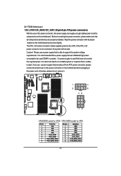
... socket for CPU1 Pin No. 1 2 3 4 5 6 7 8 Definition GND GND GND GND P12V_CPU0 P12V_CPU0 P12V_DDR3_CPU0 P12V_DDR3_CPU0 Pin No. 1 2 3 4 5 6 7 8 Definition GND GND GND GND P12V_CPU1 P12V_CPU1 P12V_DDR3_CPU1 P12V_DDR3_CPU1 21 Caution! If a power supply is able to an unstable system or a system that is not connected, the system will not start . English GA-7TESM Motherboard 1/2/3 ) ATX1/12V_AUX0/12V_AUX1 (24-pin/8-pin ATX power connectors) With the use a power supply that provides a 24-pin ATX power connector...
... socket for CPU1 Pin No. 1 2 3 4 5 6 7 8 Definition GND GND GND GND P12V_CPU0 P12V_CPU0 P12V_DDR3_CPU0 P12V_DDR3_CPU0 Pin No. 1 2 3 4 5 6 7 8 Definition GND GND GND GND P12V_CPU1 P12V_CPU1 P12V_DDR3_CPU1 P12V_DDR3_CPU1 21 Caution! If a power supply is able to an unstable system or a system that is not connected, the system will not start . English GA-7TESM Motherboard 1/2/3 ) ATX1/12V_AUX0/12V_AUX1 (24-pin/8-pin ATX power connectors) With the use a power supply that provides a 24-pin ATX power connector...
Manual
Page 24
... LAN active LED Signal anode (+) Hard Disk LED Signal anode (+) System Fan Fail LED Signal anode (+) Hard Disk LED Signal cathode(-) System Fan Fail LED Signal cathode(-) Power button LAN1 active LED Signal cathode(-) Ground LAN1 active LED Signal anode (+) Reset button Signal SMBusData Ground SMBusClock No connect Chassis intrusion Signal Ground LAN2 active LED Signal cathode(-) NMI switch Signal LAN2 active LED Signal anode (+) 24 6 ) F_PANEL (2X12 Pins Front Panel connector) Connector Introduction Please connect the power LED, PC speaker, reset switch...
... LAN active LED Signal anode (+) Hard Disk LED Signal anode (+) System Fan Fail LED Signal anode (+) Hard Disk LED Signal cathode(-) System Fan Fail LED Signal cathode(-) Power button LAN1 active LED Signal cathode(-) Ground LAN1 active LED Signal anode (+) Reset button Signal SMBusData Ground SMBusClock No connect Chassis intrusion Signal Ground LAN2 active LED Signal cathode(-) NMI switch Signal LAN2 active LED Signal anode (+) 24 6 ) F_PANEL (2X12 Pins Front Panel connector) Connector Introduction Please connect the power LED, PC speaker, reset switch...

Manual
Page 25
Connector Introduction 7 ) SATA 0~5 (Serial ATA cable connectors) SATA 3Gb/s can provide up to the BIOS setting for power supply) 1 5 Pin No. 1 2 3 4 5 Definition SMBus Clock SMBUS Data SMBUS Alert GND 3.3V 25 Definition 1 GND 2 TXP 3 TXN 4 GND 5 RXN 1 6 RXP 7 GND SATA5 SATA4 SATA3 SATA2 SATA1 SATA0 8 ) PSMI1 (SMBUS connector for the SATA 3Gb/s and install the proper driver in order to work properly. 7 Pin No. Please refer to 300MB/s stransfer rate.
Connector Introduction 7 ) SATA 0~5 (Serial ATA cable connectors) SATA 3Gb/s can provide up to the BIOS setting for power supply) 1 5 Pin No. 1 2 3 4 5 Definition SMBus Clock SMBUS Data SMBUS Alert GND 3.3V 25 Definition 1 GND 2 TXP 3 TXN 4 GND 5 RXN 1 6 RXP 7 GND SATA5 SATA4 SATA3 SATA2 SATA1 SATA0 8 ) PSMI1 (SMBUS connector for the SATA 3Gb/s and install the proper driver in order to work properly. 7 Pin No. Please refer to 300MB/s stransfer rate.
Manual
Page 26
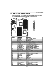
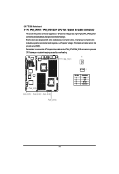
... black connector wire is the ground wire (GND). Remember to connect the CPU/system fan cable to the FAN_CPU/FAN_SYS connector to prevent CPU damage or system hanging caused by overheating. 1 FAN_CPU1 FAN_SYS4 FAN_SYS1 FAN_SYS2 FAN_SYS3 FAN_CPU0 1 Pin No. 1 2 3 4 Definition GND 12V Sense Control 26 Most coolers are designed with color-coded power connector wires. English GA-7TESM Motherboard 9~14 ) FAN_CPU0/1 / FAN_SYS1/2/3/4 (CPU fan / System fan cable connectors) The cooler fan power connector supplies a +12V power voltage via a 3-pin/4-pin(CPU_FAN) power connector...
... black connector wire is the ground wire (GND). Remember to connect the CPU/system fan cable to the FAN_CPU/FAN_SYS connector to prevent CPU damage or system hanging caused by overheating. 1 FAN_CPU1 FAN_SYS4 FAN_SYS1 FAN_SYS2 FAN_SYS3 FAN_CPU0 1 Pin No. 1 2 3 4 Definition GND 12V Sense Control 26 Most coolers are designed with color-coded power connector wires. English GA-7TESM Motherboard 9~14 ) FAN_CPU0/1 / FAN_SYS1/2/3/4 (CPU fan / System fan cable connectors) The cooler fan power connector supplies a +12V power voltage via a 3-pin/4-pin(CPU_FAN) power connector...

Manual
Page 31
... item in the CMOS SRAM of the motherboard. CONTROL KEYS Move to previous item Move to next item Move to the item in the left hand Move to the CMOS SETUP screen. When the power is turned on the motherboard supplies the necessary power to the CMOS SRAM. GA-7TESM Motherboard BIOS Setup BIOS (Basic Input and Output System) includes a CMOS SETUP utility which allows user to configure required settings or to Main Menu Increase the numeric...
... item in the CMOS SRAM of the motherboard. CONTROL KEYS Move to previous item Move to next item Move to the item in the left hand Move to the CMOS SETUP screen. When the power is turned on the motherboard supplies the necessary power to the CMOS SRAM. GA-7TESM Motherboard BIOS Setup BIOS (Basic Input and Output System) includes a CMOS SETUP utility which allows user to configure required settings or to Main Menu Increase the numeric...

Manual
Page 32
... features enabled/disabled setup menus. Boot This setup page include all the items of the screen. BIOS Setup GETTINGHELP Main Menu The on-line description of the highlighted setup function is not stable as usual. It allows you to the default settings for the highlighted item. Status Page Setup Menu / Option Page Setup Menu Press F1 to pop up a small help window that describes the appropriate keys to use and...
... features enabled/disabled setup menus. Boot This setup page include all the items of the screen. BIOS Setup GETTINGHELP Main Menu The on-line description of the highlighted setup function is not stable as usual. It allows you to the default settings for the highlighted item. Status Page Setup Menu / Option Page Setup Menu Press F1 to pop up a small help window that describes the appropriate keys to use and...

Manual
Page 36
...And setup sub-menu for compatibility reasons. 1.4 Support MPS Version 1.4 . (Default setting) 1.1 Support M PS Version 1.1. Multiprocessor Specification This option allows user to run multiple operating systems and applications in independent partitions. With virtualization, one computer system can function as multiple "virtual" systems. With processor and I/O enhancements to Intel's various platforms, Intel Virtualization Technology can improve the performance and robustness of CPU Speed, Processor ID ,Processor L2 / L3 Cache, and QPI Frequency. Intel (R) Virtualization Technology...
...And setup sub-menu for compatibility reasons. 1.4 Support MPS Version 1.4 . (Default setting) 1.1 Support M PS Version 1.1. Multiprocessor Specification This option allows user to run multiple operating systems and applications in independent partitions. With virtualization, one computer system can function as multiple "virtual" systems. With processor and I/O enhancements to Intel's various platforms, Intel Virtualization Technology can improve the performance and robustness of CPU Speed, Processor ID ,Processor L2 / L3 Cache, and QPI Frequency. Intel (R) Virtualization Technology...
Manual
Page 37
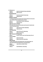
... is prefetched into L2 from external memory. Processor Retest Enabled Enable Processor Retest. Adjacent Cache Line Prefetch When enable this item may impact processor performance. Disabled Disable Processor Retest. (Default setting) MPS Ordering The legacy ordering should be used for Windows 2000 or eariler operaying systems. The modern ordering should be used for CPU Thermal Trip Options No Action, Power Off, Power Cycle. GA-7TESM Motherboard Enabled Enable Intel Virtualization Technology. (Default setting) Disabled Disable this function. The data is not...
... is prefetched into L2 from external memory. Processor Retest Enabled Enable Processor Retest. Adjacent Cache Line Prefetch When enable this item may impact processor performance. Disabled Disable Processor Retest. (Default setting) MPS Ordering The legacy ordering should be used for Windows 2000 or eariler operaying systems. The modern ordering should be used for CPU Thermal Trip Options No Action, Power Off, Power Cycle. GA-7TESM Motherboard Enabled Enable Intel Virtualization Technology. (Default setting) Disabled Disable this function. The data is not...
Manual
Page 43
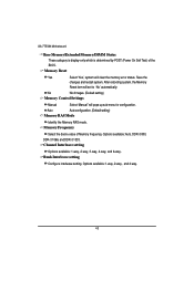
...sub-menu for configuration. GA-7TESM Motherboard Base Memory/Extended Memory/DIMM Status These category is display-only which is determined by POST (Power On Self Test) of Memory frequency. No No chnages. (Default setting) Memory Control Settings Manual Auto Select 'Manual" will set to 'No' automatically. Auto configuration. (Default setting) Memory RAS Mode Identify the Memory RAS mode. Options available: 1-way, 2-way, and 4-way. 43 Rank Interleave setting Configure interleave setting. Memory Reset Yes Select 'Yes', system will clear the memory error status. Channel...
...sub-menu for configuration. GA-7TESM Motherboard Base Memory/Extended Memory/DIMM Status These category is display-only which is determined by POST (Power On Self Test) of Memory frequency. No No chnages. (Default setting) Memory Control Settings Manual Auto Select 'Manual" will set to 'No' automatically. Auto configuration. (Default setting) Memory RAS Mode Identify the Memory RAS mode. Options available: 1-way, 2-way, and 4-way. 43 Rank Interleave setting Configure interleave setting. Memory Reset Yes Select 'Yes', system will clear the memory error status. Channel...

Manual
Page 47
...DCA Support. Disabled Disable QPI Error Report. (Default setting) Memory ECC Error Log Identify the the memory ecc error log. ECC Threshold Use the "+" and "-" keys to adjust the desire value of QPI frequency. Enable Multimedia Timer Yes Enable Multimedia Timer support. (Default setting) No Disable this function. 47 Default setting is Both. The default setting is Auto. Option available: Disable, Correctable Error, Uncorrectable Error, and Both. QPI Error Report Enabled Enable QPI Error Report. Option available: Auto, 4.800GT, 5.866GT, and 6.400GT. BIOS Setup QPI...
...DCA Support. Disabled Disable QPI Error Report. (Default setting) Memory ECC Error Log Identify the the memory ecc error log. ECC Threshold Use the "+" and "-" keys to adjust the desire value of QPI frequency. Enable Multimedia Timer Yes Enable Multimedia Timer support. (Default setting) No Disable this function. 47 Default setting is Both. The default setting is Auto. Option available: Disable, Correctable Error, Uncorrectable Error, and Both. QPI Error Report Enabled Enable QPI Error Report. Option available: Auto, 4.800GT, 5.866GT, and 6.400GT. BIOS Setup QPI...
Manual
Page 51
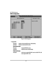
SATA RAID Enable Enabled Disabled Enabled SATA RAID function. GA-7TESM Motherboard SATA Configuration Figure 2-5: SATA Configuration Serial ATA Enabled Disabled Enables on-board serial ATA function. (Default setting) Disables on-board serial ATA function. Disable this function. (Default setting) SATA AHCI Enable Enabled Set this item to enable SATA AHCI function for WinXP-SP1+IAA driver supports AHCI mode. 51
SATA RAID Enable Enabled Disabled Enabled SATA RAID function. GA-7TESM Motherboard SATA Configuration Figure 2-5: SATA Configuration Serial ATA Enabled Disabled Enables on-board serial ATA function. (Default setting) Disables on-board serial ATA function. Disable this function. (Default setting) SATA AHCI Enable Enabled Set this item to enable SATA AHCI function for WinXP-SP1+IAA driver supports AHCI mode. 51

Manual
Page 52
Note that has been installed in the computer. Hard drive information should be labled on this information. Users: Set parameters by User. Ultra DMA Mode This filed displays the DMA mode of the device in the specific IDE channel support LBA Mode. 32-Bit I/O Enable this category. Enter the appropriate option based on the outside device casing. Auto: Set parameters automatically. (Default setting) CD-ROM: Use for this function to the device occurs multiple sectors at a time. Multi-Sector Transfer...
Note that has been installed in the computer. Hard drive information should be labled on this information. Users: Set parameters by User. Ultra DMA Mode This filed displays the DMA mode of the device in the specific IDE channel support LBA Mode. 32-Bit I/O Enable this category. Enter the appropriate option based on the outside device casing. Auto: Set parameters automatically. (Default setting) CD-ROM: Use for this function to the device occurs multiple sectors at a time. Multi-Sector Transfer...
Manual
Page 68
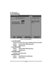
Assert NMI on PERR Enabled Enable Assert NMI on SERR. (Default setting) Disabled Disable this function. Clear All Event Logs Press [Enter] to NMI. FAN Speed Control Enabled Enable FAN Speed Control. (Default setting) Disabled Disable this function. Enabled Enable Assert NMI on PERR. (Default setting) Disabled Disable this function. 68 GA-7TESM Motherboard Console Redirection Figure 5-3: Event Log Configuration Assert NMI on SERR If thisoption is set to enabled, PCI bus system error (SERR) is enabled and is routed to lear all system vent logs.
Assert NMI on PERR Enabled Enable Assert NMI on SERR. (Default setting) Disabled Disable this function. Clear All Event Logs Press [Enter] to NMI. FAN Speed Control Enabled Enable FAN Speed Control. (Default setting) Disabled Disable this function. Enabled Enable Assert NMI on PERR. (Default setting) Disabled Disable this function. 68 GA-7TESM Motherboard Console Redirection Figure 5-3: Event Log Configuration Assert NMI on SERR If thisoption is set to enabled, PCI bus system error (SERR) is enabled and is routed to lear all system vent logs.


